STMicroelectronics STEVAL-C34KAT1 Vibrometer and Temperature Sensor Expansion Kit
Introduction
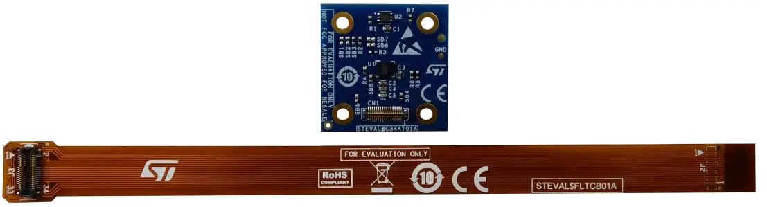
The STEVAL-C34KAT1 is a multisensing expansion kit that includes the STEVAL-C34AT01 expansion board and a flexible cable.
The small form factor and the accurate design allow a precise measurement of vibrations up to the sensor bandwidth (6 kHz) as well as of the temperature.
The IIS3DWB vibration sensor is soldered at the center of the small 25 x 25 mm board. The STTS22H temperature sensor is placed on the PCB side and is thermally coupled to the PCB bottom exposed pad through vias.
The expansion board can be mounted on the equipment for the vibration analysis using the four holes or the double-sided adhesive tape. This board is compatible with the STWIN.box kit (STEVAL STWINBX1).
Figure 1. STEVAL-C34KAT1 expansion kit
Features
- Kit content:
– a STEVAL-C34AT01 multisensing expansion board (25x25mm) with a 34-pin board to-FPC connector
– a 34-pin flexible cable - Ideal plug-in for the STEVAL-STWINBX1 evaluation board
- Ultra-wide bandwidth (up to 6 kHz), low-noise, 3-axis digital vibration sensor (IIS3DWB):
– Ultra-wide and flat frequency response range: from DC to 6 kHz (±3 dB point)
– Low-pass or high-pass filter with a selectable cut-off frequency
– 1.1 mA with the three axes at full performance
– Extended temperature range from -40 to +105°C - Low-voltage, ultra-low-power, 0.5°C accuracy I²C/SMBus 3.0 temperature sensor (STTS22H)
– Programmable thresholds through an interrupt pin
– Ultra-low current: 1.75 µA in one-shot mode
– Operating temperature -40 to +125° - Exposed pad on the bottom side to improve the thermal coupling for the temperature sensor
- 2.1 to 3.3 V power supply input
Precautions for use
Important: This kit is not immune to indirect electrostatic discharges. During the ESD test, the kit has obtained level C. This means that the expansion board has not been damaged during the test, but the intervention of the operator was necessary to reset it. When an electrostatic discharge is applied to an adjacent object, the board might interrupt its functioning. In this case, the intervention of an operator is required to reset the board (that is, to unplug and replug the power supply line).
If the board is attached to a STEVAL-STWINBX1 (STWIN.box), you can control the power supply of the external 34- pin connector via software, by leveraging the power switch functionality of the STBC02 battery charger IC.
The STEVAL-C34KAT1 expansion board can be used with the STEVAL-STWINBX1 kit (STWIN box).
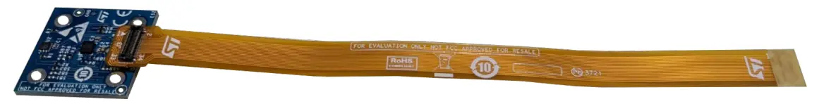
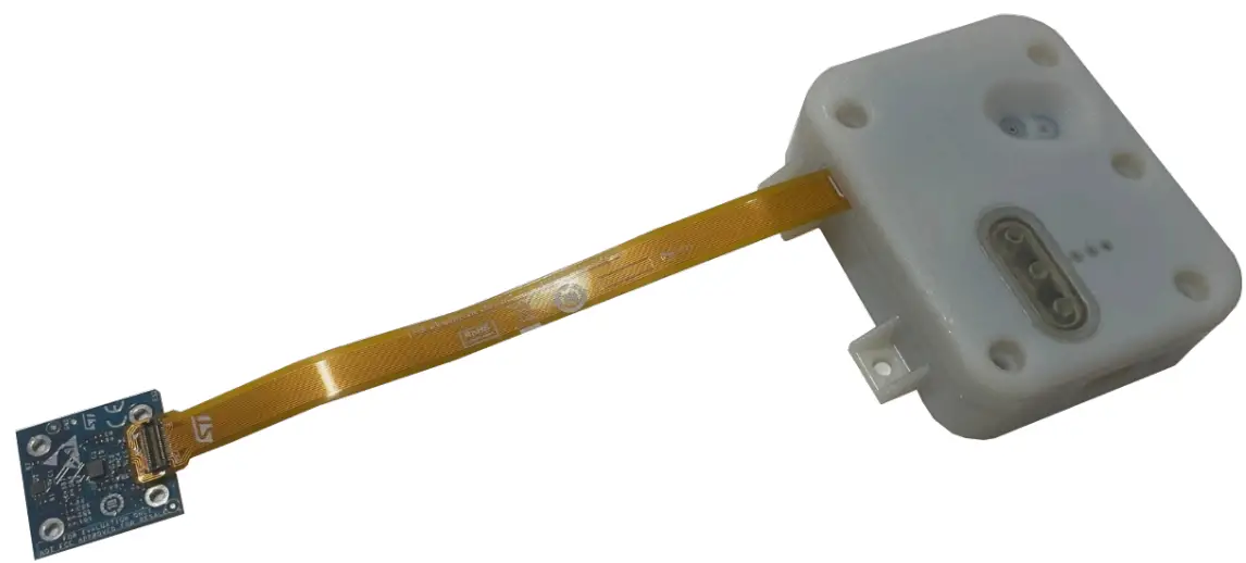
The device can be attached to the STWIN. box using the provided flexible cable, through the 34-pin connectors available on both platforms.
Figure 2. Expansion board and flexible cable
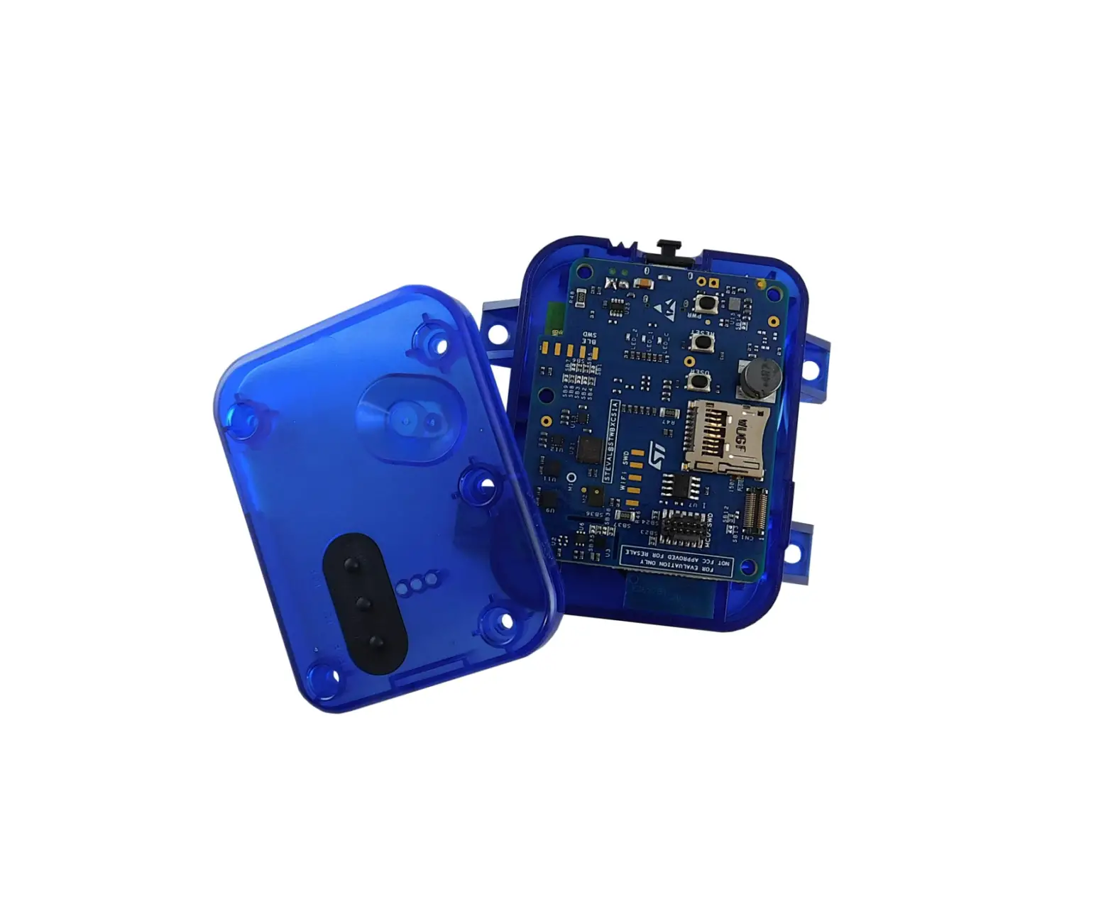
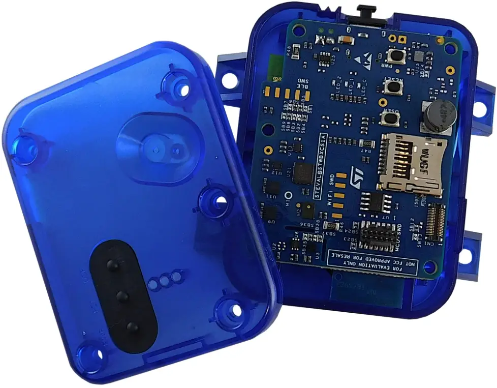
To plug the flexible cable onto the STWIN. box, remove the plastic case cover.
Figure 3. Plugging the flexible cable onto the STWIN. box
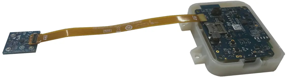
You can then remount the cover, as it leaves enough space for the flexible cable
Figure 4. Final setup
The easiest way to read data from the STEVAL-C34KAT1 sensors is to flash the STWIN. box with the FP-SNSDATALOG2 function pack compiled with the external sensor option. The firmware package provides a ready to use, precompiled binary.
Adhesive tape
The kit provides a few samples of 3M™ 9088 high performance, double coated tape. These samples can be used to mount the board on the equipment for vibration analysis.
Alternatively, you can mount the board through the holes located at each corner of the PCB.
The small form factor of the PCB ensures no resonances and a flat frequency response for the complete bandwidth of the sensor (up to 6 kHz).
Schematic diagrams
Figure 5. STEVAL-C34KAT1 circuit schematic: STEVAL-C34AT01
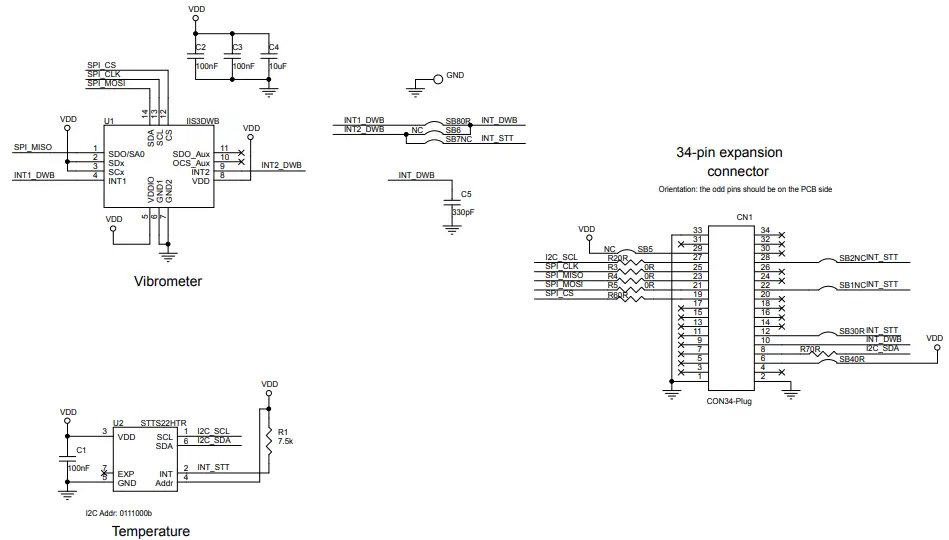
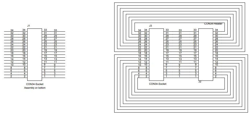
Figure 6. STEVAL-C34KAT1 circuit schematic: STEVAL-FLTCB01
Bill of materials
Table 1. STEVAL-C34KAT1 bill of materials
| Item | Q.ty | Ref. | Part/value | Description | Manufacturer | Order code |
| 1 | 1 | Table 2. Expansi on board bill of materials | STEVAL- C34AT01 | Vibrometer and temperature expansion board | ST | Not available for separate sale |
| 2 | 1 | Table 3. Flexible cable bill of materials | STEVAL- FLTCB01 | 34-pin, 15 cm flexible cable | ST | Not available for separate sale |
| 3 | 4 | – | 3M 9088 – 25×25 mm, 25×25 mm | 3M™ high performance, double coated tape | 3M | 9088 |
Table 2. Expansion board bill of materials
| Item | Q.ty | Ref. | Value | Description | Manufacturer | Order code |
| 1 | 1 | CN1 | CON34-Plug, 34 positions, SMD, gold | Connector socket | Panasonic Electric Works | AXF6G3412A |
| 2 | 3 | C1, C2, C3 | 100 nF, 0402 (1005 metric), 16 V, ±10%, X7R | Ceramic capacitors | Murata Electronics North America | GRM155R71C104KA8 8J |
| 3 | 1 | C4 | 10 µF, 0402 (1005 metric), 10 V, ±20%,X5R | Ceramic capacitor | Samsung Electro- Mechanics America, Inc. | CL05A106MP8NUB8 |
| 4 | 1 | C5 | 330pF, 0402 (1005 Metric), 10%, | CAP CER 330pF | Murata Electronics North America | GRM1555C1H331GA0 1D |
| 5 | 1 | R1 | 7.5 k, 0402 (1005 metric), 1/16 W, ±5%, SMD | Resistor | Yageo | RC0402JR-077K5L |
| 6 | 9 | R2, SB3, R3, SB4, R4, R5, R6, R7, SB8 | 0 R, 0402 (1005 metric), SMD | Resistors | Vishay Dale | CRCW04020000Z0ED |
| 7 | 0 | SB1, SB2, SB5, SB6, SB7 | 0 ohm, 0402 (1005 metric), SMD | Resistors (not mounted) | Vishay Dale | CRCW04020000Z0ED |
| 8 | 1 | U1 | IIS3DWBTR, VFLGA2.5X3X.8 6 14L P.5 L.475X.25 | Ultra-wide bandwidth, low- noise, 3-axis digital vibration sensor | ST | IIS3DWBTR |
| 9 | 1 | U2 | STTS22HTR, UDFN 2X2X.55 6L pitch 0.65 | Low-voltage, ultra-low-power, 0.5°C accuracy I²C/SMBus 3.0 temperature sensor | T | STTS22HTR |
Table 3. Flexible cable bill of material
| Item | Q.ty | Ref. | Part/value | Description | Manufacturer | Order code |
| 1 | 1 | J2 | CON34-Header, 34 positions, SMD, gold | Connector header | Panasonic Electric Works | AXF5G3412A |
| 2 | 2 | J1, J3 | CON34-Socket, 34 positions, SMD, gold | Connector sockets | Panasonic Electric Works | AXF6G3412A |
Kit versions
Table 4. STEVAL-C34KAT1 versions
| PCB version | Schematic diagrams | Bill of materials |
| STEVAL$C34KAT1A (1) | STEVAL$C34KAT1A schematic diagrams | STEVAL$C34KAT1A bill of materials |
Regulatory compliance information
Formal Notice Required by the U.S. Federal Communications Commission
FCC NOTICE
This kit is designed to allow:
(1) Product developers to evaluate electronic components, circuitry, or software associated with the kit to determine whether to incorporate such items in a finished product and (2) Software developers to write software applications for use with the end product.
This kit is not a finished product and when assembled may not be resold or otherwise marketed unless all required FCC equipment authorizations are first obtained. Operation is subject to the condition that this product not cause harmful interference to licensed radio stations and that this product accept harmful interference. Unless the assembled kit is designed to operate under part 15, part 18 or part 95 of this chapter, the operator of the kit must operate under the authority of an FCC license holder or must secure an experimental authorization under part 5 of this chapter 3.1.2.
Table 5. Document revision history
| Date | Revision | Changes |
| 15-Dec-2022 | 1 | Initial release. |

References
 STMicroelectronics: Our technology starts with you
-
STMicroelectronics Trademark List - STMicroelectronics
-
IIS3DWB - Ultra-wide bandwidth, low-noise, 3-axis digital vibration sensor - STMicroelectronics
-
STBC02 - Li-Ion linear battery charger with LDO, load switches and reset generator - STMicroelectronics
-
STEVAL-C34KAT1 - Vibrometer and temperature sensor expansion kit - STMicroelectronics
-
STEVAL-STWINBX1 - STWIN.box - SensorTile Wireless Industrial Node Development Kit - STMicroelectronics
-
STTS22H - Low-voltage, ultra-low-power, 0.5 °C accuracy I2C/SMBus 3.0 temperature sensor - STMicroelectronics


