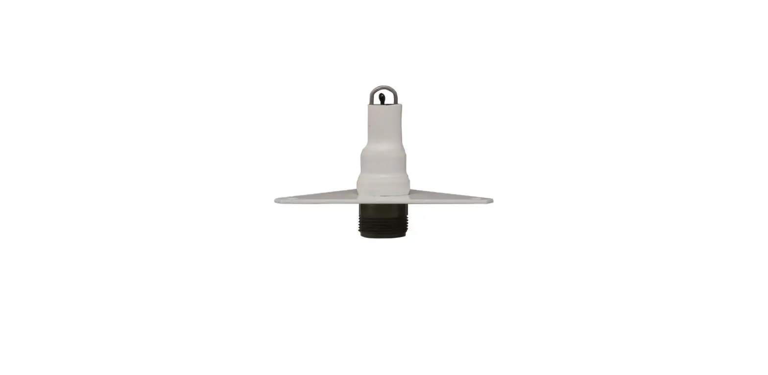
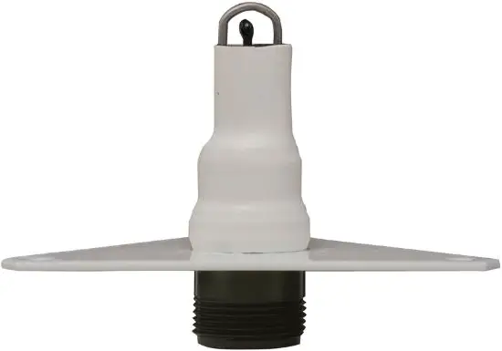
MET ONE INSTRUMENTS 061 Temperature Sensor
GENERAL INFORMATION
- Models 061 and 063 are precision thermistor temperature sensors. For the most accurate air temperature measurements, the sensors are always mounted in a radiation shield, which minimizes errors caused by solar and terrestrial radiation heating. Sensors produce resistance change inversely proportional to temperature.
- Model 061 is designed for air temperature measurement. The Model 061 has a time constant of only 10 seconds.
- Model 063 is designed for the direct measurement of air, soil, and water temperature. The 063 sensors is completely sealed in a stainless steel housing, filled with silicone oil.
- The Model 063 has a time constant of 60 seconds.
Sensor Cable and Connections
All sensors are supplied with signal leads one foot in length. Dependent on particular applications, longer cable lengths,s, and cable connectors may be provided as an option.
INSTALLATION
Temperature Sensor Installation
- A. AIR TEMPERATURE
For maximum accuracy, it is desirable to mount the temperature sensor in a radiation shield. The radiation shield will minimize the effects of solar and terrestrial radiation and will additionally provide adequate airflow over the sensor. Mechanical mounting information is given in the radiation shield manual. - B. SOIL TEMPERATURE
Model 063 is used for soil temperature measurements. Installation of the soil temperature probe requires the digging of a small hole to the required measurement depth in firm, undisturbed soil. The probe is inserted horizontally into this firm soil, and the soil is replaced in the hole and packed firmly. - C. WATER TEMPERATURE
The Model 063 Temperature Sensor should be placed in water, free from heat radiation sources. - D. These sensors are durable, field-proven devices; however,
DO NOT DROP OR EXPOSE THE SENSOR TO HEAVY SHOCK!!!
Wiring Connections
The output of the thermistor sensor is a relatively high resistance that varies according to temperature. It is important not to introduce any parallel resistance paths. A parallel resistance path may be established by a dirt/moisture build-up between two sensor leads. This may occur in poorly made splices and unprotected connections. It is advisable to always use a protective coating on exposed sensor connections. Use a coating such as silastic rubber (RTV).
Direct Wiring to a Met One Instruments Translator
When the sensor is connected directly to a Met One Instruments Translator Module the sensor is loaded with the appropriate resistor to provide a linear output.
Direct Connection to a Data Logger
When the sensor is connected to a data logger the data logger must have a terminating resistor to provide a linear output. Refer to Figure 2-1.
OPERATIONAL CHECK-OUT AND CALIBRATION
Temperature Sensor Check-out
Compare sensor readings against a precision mercury thermometer. Use a Lo Current Digital Ohmmeter and compare readings of temperature vs. resistance.
MAINTENANCE AND TROUBLESHOOTING
General Maintenance Schedule
- 6 – 12 Month Intervals:
- A. Inspect the sensor for proper operation per Section 3.1.
- The schedule is based on average to adverse environments.
Troubleshooting Procedures
A. Incorrect sensor signal: check sensor input connections: check temperature vs. sensor output signal using Table 3-1. Verify that the sensor has the correct terminating resistor if not used with a Met One Translator.
Table 1-1
Sensor Specifications
| MODEL | MAXIMUM RANGE | LINEARITY | ACCURACY | TIME CONSTANT | CABLE LENGTH | CONNECTOR |
| 061 | -30°C to +50°C | ± 0.16°C | ± 0.15°C | 10 seconds | 1 foot | none |
| 063-2 | 0°C to +100° C | ± 0.21°C | ± 0.15°C | 60 seconds | 50 feet | none |
| 063-3 | -30°C to +50°C | ± 0.16°C | ± 0.15°C | 10 seconds | 1 foot | none |
Temperature Sensor Calibration
The sensors are tested for calibration conformity at the factory. Field calibration may be verified by testing and sensors against themselves or against a known standard. It is not possible to make alterations to the sensor’s calibration, as it is fixed.
Ice Bath (0C Calibration Test)
This calibration test requires that a practical reference point of 0C be obtained by the preparation of a mixture of shaved or finely cracked ice and enough water to cover but not float the ice. To create a precision ice bath ( 0.002C), distilled water must be used for the bath and to make the ice. This mixture is made and contained in a large wide-mouth Dewar flask with a capacity of about one quart or more. The Dewar flask is stopped up with a cork or other suitable material, with two holes provided for the insertion of both the temperature and a glass thermometer. Both the probe and thermometer are inserted into the Dewar flask so that the tips of each are at least 4 ½ inches below the surface of the mixture, ½ inch from the sides of the Dewar with a minimum of one inch remaining below. Using a precision volt-ohmmeter: measure the resistance vs. temperature as given in Table 3-1.
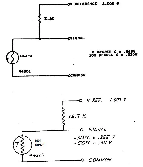
Figure 2-1 Connections of 061/063 Temperature Sensor To Datalogger
Table 3-1A Model 063-2 RESISTANCE CHART DEG C
| TEMP DEG C | RCAL | TEMP DEG C | RCAL |
| 0 | 20516 | 51 | 4649 |
| 1 | 19612 | 52 | 4547 |
| 2 | 18774 | 53 | 4448 |
| 3 | 17996 | 54 | 4352 |
| 4 | 17271 | 55 | 4258 |
| 5 | 16593 | 56 | 4166 |
| 6 | 15960 | 57 | 4076 |
| 7 | 15365 | 58 | 3989 |
| 8 | 14806 | 59 | 3903 |
| 9 | 14280 | 60 | 3820 |
| 10 | 13784 | 61 | 3739 |
| 11 | 13315 | 62 | 3659 |
| 12 | 12872 | 63 | 3581 |
| 13 | 12451 | 64 | 3505 |
| 14 | 12052 | 65 | 3431 |
| 15 | 11673 | 66 | 3358 |
| 16 | 11312 | 67 | 3287 |
| 17 | 10969 | 68 | 3218 |
| 18 | 10641 | 69 | 3150 |
| 19 | 10328 | 70 | 3083 |
| 20 | 10029 | 71 | 3018 |
| 21 | 9743 | 72 | 2954 |
| 22 | 9469 | 73 | 2891 |
| 23 | 9206 | 74 | 2830 |
| 24 | 8954 | 75 | 2769 |
| 25 | 8712 | 76 | 2710 |
| 26 | 8479 | 77 | 2653 |
| 27 | 8256 | 78 | 2596 |
| 28 | 8041 | 79 | 2540 |
| 29 | 7833 | 80 | 2486 |
| 30 | 7633 | 81 | 2432 |
| 31 | 7441 | 82 | 2380 |
| 32 | 7255 | 83 | 2328 |
| 33 | 7075 | 84 | 2278 |
| 34 | 6902 | 85 | 2228 |
| 35 | 6734 | 86 | 2179 |
| 36 | 6572 | 87 | 2131 |
| 37 | 6415 | 88 | 2084 |
| 38 | 6263 | 89 | 2038 |
| 39 | 6115 | 90 | 1992 |
| 40 | 5973 | 91 | 1948 |
| 41 | 5834 | 92 | 1904 |
| 42 | 5700 | 93 | 1861 |
| 43 | 5569 | 94 | 1818 |
| 44 | 5443 | 95 | 1776 |
| 45 | 5320 | 96 | 1735 |
| 46 | 5200 | 97 | 1695 |
| 47 | 5084 | 98 | 1655 |
| 48 | 4970 | 99 | 1616 |
| 49 | 4860 | 100 | 1578 |
| 50 | 4753 |
VALUE WITH 3200 OHM RESISTOR IN PARALLEL WITH SENSOR
RANGE 0C TO 100C THERMISTOR BEAD 44201
Table 3-1B Model 063-2 RESISTANCE CHART DEG F
| TEMP DEG F | RCAL | TEMP DEG F | RCAL |
| 32 | 20516 | 84 | 7856 |
| 33 | 20005 | 85 | 7744 |
| 34 | 19516 | 86 | 7633 |
| 35 | 19047 | 87 | 7526 |
| 36 | 18596 | 88 | 7420 |
| 37 | 18164 | 89 | 7316 |
| 38 | 17748 | 90 | 7214 |
| 39 | 17349 | 91 | 7115 |
| 40 | 16964 | 92 | 7017 |
| 41 | 16593 | 93 | 6921 |
| 42 | 16236 | 94 | 6827 |
| 43 | 15892 | 95 | 6734 |
| 44 | 15559 | 96 | 6643 |
| 45 | 15238 | 97 | 6554 |
| 46 | 14928 | 98 | 6467 |
| 47 | 14627 | 99 | 6381 |
| 48 | 14337 | 100 | 6296 |
| 49 | 14056 | 101 | 6213 |
| 50 | 13784 | 102 | 6132 |
| 51 | 13520 | 103 | 6051 |
| 52 | 13265 | 104 | 5973 |
| 53 | 13017 | 105 | 5895 |
| 54 | 12776 | 106 | 5819 |
| 55 | 12543 | 107 | 5744 |
| 56 | 12316 | 108 | 5670 |
| 57 | 12095 | 109 | 5598 |
| 58 | 11881 | 110 | 5527 |
| 59 | 11673 | 111 | 5456 |
| 60 | 11470 | 112 | 5387 |
| 61 | 11273 | 113 | 5320 |
| 62 | 11081 | 114 | 5253 |
| 63 | 10894 | 115 | 5187 |
| 64 | 10712 | 116 | 5122 |
| 65 | 10535 | 117 | 5058 |
| 66 | 10362 | 118 | 4995 |
| 67 | 10193 | 119 | 4933 |
| 68 | 10029 | 120 | 4873 |
| 69 | 9868 | 121 | 4812 |
| 70 | 9712 | 122 | 4753 |
| 71 | 9559 | 123 | 4695 |
| 72 | 9409 | 124 | 4638 |
| 73 | 9263 | 125 | 4581 |
| 74 | 9121 | 126 | 4525 |
| 75 | 8981 | 127 | 4470 |
| 76 | 8845 | 128 | 4416 |
| 77 | 8712 | 129 | 4362 |
| 78 | 8582 | 130 | 4310 |
| 79 | 8454 | 131 | 4258 |
| 80 | 8329 | 132 | 4206 |
| 81 | 8207 | 133 | 4156 |
| 82 | 8088 | 134 | 4106 |
| 83 | 7971 | 135 | 4057 |
- VALUE WITH 3200 OHM RESISTOR IN PARALLEL WITH SENSOR
- RANGE 32F TO 212F THERMISTOR BEAD 44201
Table 3-1B (continued) Model 063-2 RESISTANCE CHART DEG F
| TEMP DEG F | RCAL | TEMP DEG F | RCAL |
| 136 | 4008 | 178 | 2426 |
| 137 | 3960 | 179 | 2397 |
| 138 | 3913 | 180 | 2368 |
| 139 | 3866 | 181 | 2340 |
| 140 | 3820 | 182 | 2311 |
| 141 | 3775 | 183 | 2283 |
| 142 | 3730 | 184 | 2255 |
| 143 | 3685 | 185 | 2228 |
| 144 | 3642 | 186 | 2201 |
| 145 | 3599 | 187 | 2174 |
| 146 | 3556 | 188 | 2147 |
| 147 | 3514 | 189 | 2121 |
| 148 | 3472 | 190 | 2094 |
| 149 | 3431 | 191 | 2069 |
| 150 | 3390 | 192 | 2043 |
| 151 | 3350 | 193 | 2018 |
| 152 | 3311 | 194 | 1992 |
| 153 | 3272 | 195 | 1967 |
| 154 | 3233 | 196 | 1943 |
| 155 | 3195 | 197 | 1918 |
| 156 | 3157 | 198 | 1894 |
| 157 | 3120 | 199 | 1870 |
| 158 | 3083 | 200 | 1846 |
| 159 | 3046 | 201 | 1823 |
| 160 | 3010 | 202 | 1800 |
| 161 | 2975 | 203 | 1776 |
| 162 | 2940 | 204 | 1754 |
| 163 | 2905 | 205 | 1731 |
| 164 | 2870 | 206 | 1708 |
| 165 | 2836 | 207 | 1686 |
| 166 | 2803 | 208 | 1664 |
| 167 | 2769 | 209 | 1642 |
| 168 | 2737 | 210 | 1621 |
| 169 | 2704 | 211 | 1599 |
| 170 | 2672 | 212 | 1578 |
| 171 | 2640 | ||
| 172 | 2608 | ||
| 173 | 2577 | ||
| 174 | 2547 | ||
| 175 | 2516 | ||
| 176 | 2486 | ||
| 177 | 2456 |
- VALUE WITH 3200 OHM RESISTOR IN PARALLEL WITH SENSOR
- RANGE 32F TO 212F
- THERMISTOR BEAD 44201
- For RCAL: Where: Tc = Temp (deg C)
- Tc = ((((Rt ‾1) + 3200 ‾1)) ‾1 – 2768.23) ∕-17.115 RT = RCAL
- Rt = ((((-17.115Tc) + 2768.23) ‾1) – (3200) ‾1) ‾1
Table 3-1C Model 061, 063-3 RESISTANCE CHART DEG C
TEMP DEG C RCAL TEMP DEG C RCAL
| -30 | 110236 | 10 | 26155 |
| -29 | 104464 | 11 | 25436 |
| -28 | 99187 | 12 | 24739 |
| -27 | 94344 | 13 | 24064 |
| -26 | 89882 | 14 | 23409 |
| -25 | 85760 | 15 | 22775 |
| -24 | 81939 | 16 | 22159 |
| -23 | 78388 | 17 | 21561 |
| -22 | 75079 | 18 | 20980 |
| -21 | 71988 | 19 | 20416 |
| -20 | 69094 | 20 | 19868 |
| -19 | 66379 | 21 | 19335 |
| -18 | 63827 | 22 | 18816 |
| -17 | 61424 | 23 | 18311 |
| -16 | 59157 | 24 | 17820 |
| -15 | 57014 | 25 | 17342 |
| -14 | 54986 | 26 | 16876 |
| -13 | 53064 | 27 | 16421 |
| -12 | 51240 | 28 | 15979 |
| -11 | 49506 | 29 | 15547 |
| -10 | 47856 | 30 | 15126 |
| -9 | 46284 | 31 | 14715 |
| -8 | 44785 | 32 | 14314 |
| -7 | 43353 | 33 | 13923 |
| -6 | 41985 | 34 | 13541 |
| -5 | 40675 | 35 | 13167 |
| -4 | 39421 | 36 | 12802 |
| -3 | 38218 | 37 | 12446 |
| -2 | 37065 | 38 | 12097 |
| -1 | 35957 | 39 | 11756 |
| 0 | 34892 | 40 | 11423 |
| 1 | 33868 | 41 | 11097 |
| 2 | 32883 | 42 | 10777 |
| 3 | 31934 | 43 | 10465 |
| 4 | 31019 | 44 | 10159 |
| 5 | 30136 | 45 | 9859 |
| 6 | 29284 | 46 | 9566 |
| 7 | 28462 | 47 | 9279 |
| 8 | 27667 | 48 | 8997 |
| 9 | 26899 | 50 | 8450 |
- VALUE WITH 18.7K RESISTOR IN PARALLEL WITH SENSOR
- RANGE –30C TO +50C THERMISTOR BEAD 44203
Table 3-1D Model 061, 063-3 RESISTANCE CHART DEG F
| TEMP DEG F | RCAL | TEMP DEG F | RCAL |
| -22 | 110236 | 33 | 34319 |
| -21 | 106964 | 34 | 33757 |
| -20 | 103855 | 35 | 33207 |
| -19 | 100895 | 36 | 32669 |
| -18 | 98075 | 37 | 32141 |
| -17 | 95385 | 38 | 31625 |
| -16 | 92816 | 39 | 31119 |
| -15 | 90361 | 40 | 30622 |
| -14 | 88011 | 41 | 30136 |
| -13 | 85760 | 42 | 29659 |
| -12 | 83602 | 43 | 29192 |
| -11 | 81532 | 44 | 28733 |
| -10 | 79543 | 45 | 28283 |
| -9 | 77632 | 46 | 27841 |
| -8 | 75794 | 47 | 27408 |
| -7 | 74025 | 48 | 26983 |
| -6 | 72321 | 49 | 26565 |
| -5 | 70678 | 50 | 26155 |
| -4 | 69094 | 51 | 25753 |
| -3 | 67565 | 52 | 25357 |
| -2 | 66088 | 53 | 24969 |
| -1 | 64661 | 54 | 24587 |
| 0 | 63281 | 55 | 24212 |
| 1 | 61946 | 56 | 23843 |
| 2 | 60654 | 57 | 23481 |
| 3 | 59402 | 58 | 23125 |
| 4 | 58190 | 59 | 22775 |
| 5 | 57014 | 60 | 22430 |
| 6 | 55874 | 61 | 22091 |
| 7 | 54768 | 62 | 21758 |
| 8 | 53694 | 63 | 21430 |
| 9 | 52651 | 64 | 21108 |
| 10 | 51637 | 65 | 20790 |
| 11 | 50652 | 66 | 20478 |
| 12 | 49695 | 67 | 20170 |
| 13 | 48763 | 68 | 19868 |
| 14 | 47856 | 69 | 19570 |
| 15 | 46974 | 70 | 19276 |
| 16 | 46114 | 71 | 18987 |
| 17 | 45277 | 72 | 18703 |
| 18 | 44461 | 73 | 18422 |
| 19 | 43666 | 74 | 18146 |
| 20 | 42890 | 75 | 17874 |
| 21 | 42134 | 76 | 17606 |
| 22 | 41395 | 77 | 17342 |
| 23 | 40675 | 78 | 17081 |
| 24 | 39972 | 79 | 16825 |
| 25 | 39285 | 80 | 16572 |
| 26 | 38614 | 81 | 16322 |
| 27 | 37958 | 82 | 16076 |
| 28 | 37317 | 83 | 15834 |
| 29 | 36691 | 84 | 15595 |
| 30 | 36078 | 85 | 15359 |
| 31 | 35479 | 86 | 15126 |
| 32 | 34892 | 87 | 14897 |
| TEMP DEG F | RCAL | TEMP DEG F | RCAL |
| 88 | 14670 | 106 | 11061 |
| 89 | 14447 | 107 | 10883 |
| 90 | 14227 | 108 | 10707 |
| 91 | 14009 | 109 | 10534 |
| 92 | 13794 | 110 | 10362 |
| 93 | 13583 | 111 | 10193 |
| 94 | 13374 | 112 | 10025 |
| 95 | 13167 | 113 | 9859 |
| 96 | 12963 | 114 | 9696 |
| 97 | 12762 | 115 | 9534 |
| 98 | 12564 | 116 | 9374 |
| 99 | 12368 | 117 | 9215 |
| 100 | 12174 | 118 | 9059 |
| 101 | 11983 | 119 | 8904 |
| 102 | 11794 | 120 | 8751 |
| 103 | 11607 | 121 | 8600 |
| 104 | 11423 | 122 | 8450 |
| 105 | 11241 |
- VALUE WITH 18.7K RESISTOR IN PARALLEL WITH SENSOR
- RANGE -22˚F TO +122˚F
- THERMISTOR BEAD 44203
- Tc= -(R*18700/(18700+R)-12175)/127.096
- Rt = -(127.096*Tc-12175)*18700/(127.096*Tc-12175+18700)
Corporate Sales & Service: 1600 Washington Blvd., Grants Pass, OR 97526, Phone (541) 471-7111, Fax (541) 471-7116 Distribution & Service: 3206 Main Street, Suite 106, Rowlett, TX 75088, Phone (972) 412-4747, Fax (972) 412-4716 http://www.metone.com.


