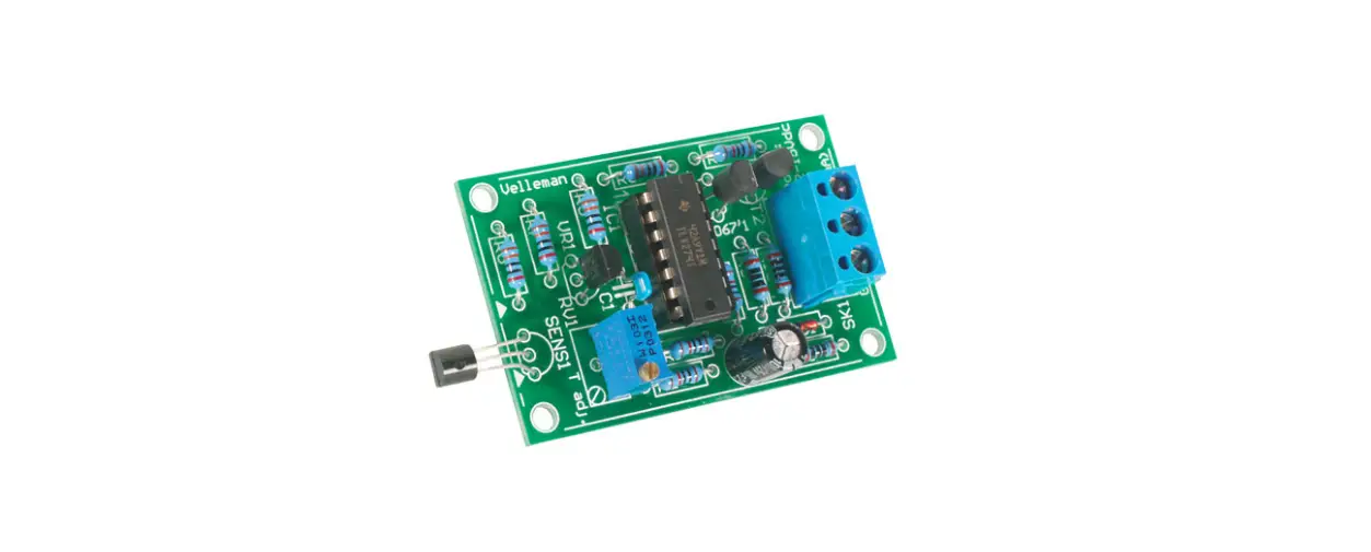
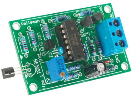
velleman K8067 Universal Temperature Sensor
Features
- Small and compact unit.
- Wide temperature range.
- One single adjustment.
- Excellent noise immunity thanks to current loop system.
- Easily adaptable for 0..5V or 0..10VDC output.
Specification
- Temp. range : -20 to +70°C
- Output : 20mA current loop
- Max. voltage : 10V in 500 ohm
- Accuracy : 2° of full range
- 3-wire system
- Power supply
- 12VDC for 0..5V OUT
- 15VDC for 0..10V OUT
- Current consumption : 30mA max.
- Dimensions : 55x35x15
Assembly hints
- Assembly (Skipping this can lead to troubles ! )
- Ok, so we have your attention. These hints will help you to make this project successful. Read them carefully.

- Make sure you have the right tools:
- A good quality soldering iron (25-40W) with a small tip.
- Wipe it often on a wet sponge or cloth, to keep it clean; then apply solder to the tip, to give it a wet look.
- This is called ‘thinning’ and will protect the tip, and enables you to make good connections.
- When solder rolls off the tip, it needs cleaning.

- Thin raisin-core solder. Do not use any flux or grease.
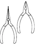
- A diagonal cutter to trim excess wires.
- To avoid injury when cutting excess leads, hold the lead so they cannot fly towards the eyes.

- Needle nose pliers, for bending leads, or to hold components in place.
- Small blade and Phillips screwdrivers. A basic range is fine.
- For some projects, a basic multi-meter is required, or might be handy


Assembly Hints
- Make sure the skill level matches your experience, to avoid disappointments.
- Follow the instructions carefully. Read and understand the entire step before you perform each operation.
- Perform the assembly in the correct order as stated in this manual
- Position all parts on the PCB (Printed Circuit Board) as shown on the drawings.
- Values on the circuit diagram are subject to changes.
- Values in this assembly guide are correct*
- Use the check-boxes to mark your progress.
- Please read the included information on safety and customer service
- Typographical inaccuracies excluded. Always look for possible last minute manual updates, indicated as ‘NOTE’ on a separate leaflet.
Soldering Hints
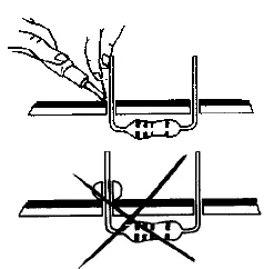
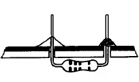
- Mount the component against the PCB surface and carefully solder the leads

- Make sure the solder joints are cone-shaped and shiny

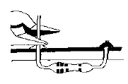
- Trim excess leads as close as possible to the solder joint

AXIAL COMPONENTS ARE TAPED IN THE CORRECT MOUNTING SEQUENCE!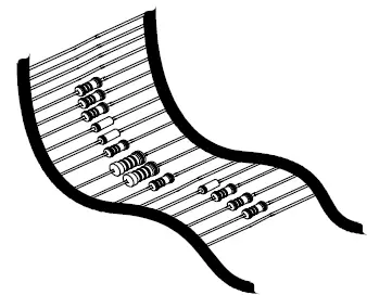
Construction
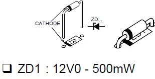
- Zener diode. Watch the polarity!

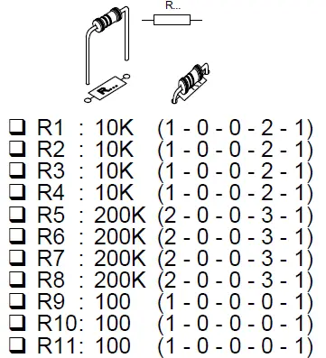
- Metal film resistors

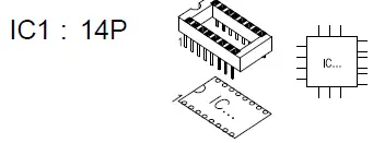
- IC socket, Watch the position of the notch!

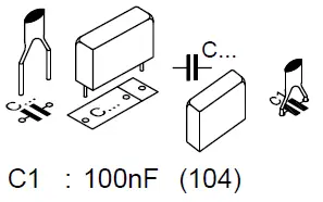
- Capacitors.
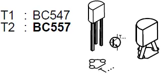
 Transistors
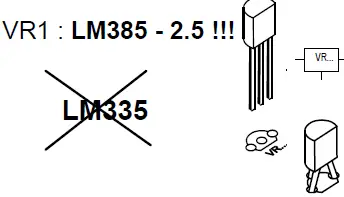
- Voltage reference

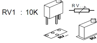
- Multiturn trimmer

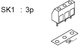
- Terminal block.

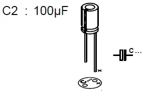
- Electrolytic Capacitor.

- Watch the polarity

- IC. Watch the position of the notch!
- Sensor LM335

 Transistors
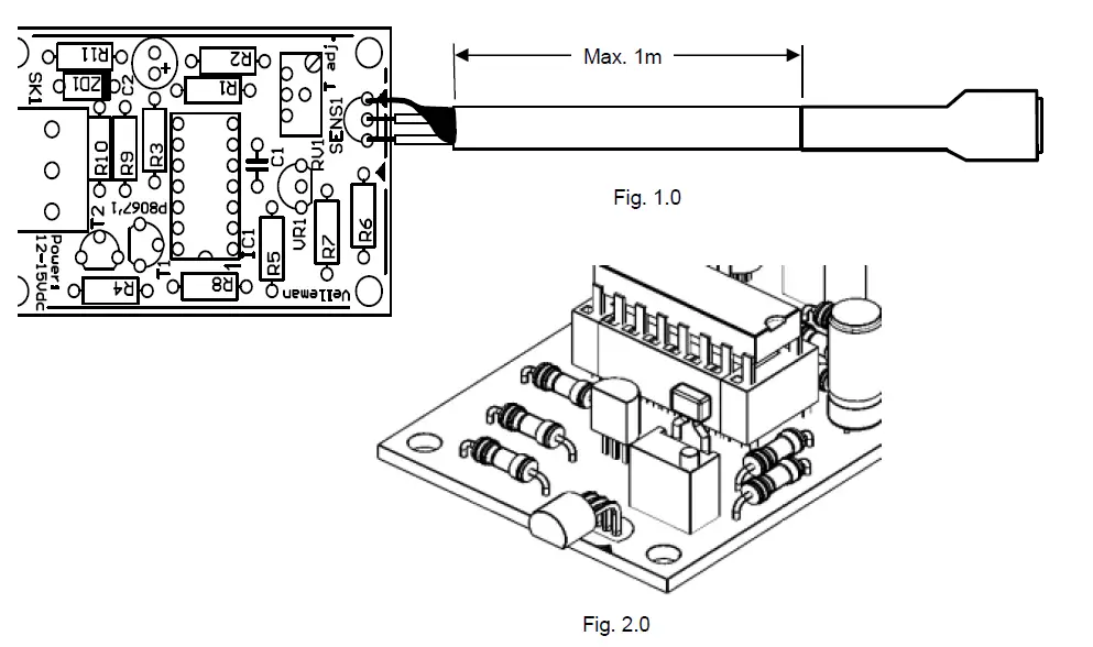
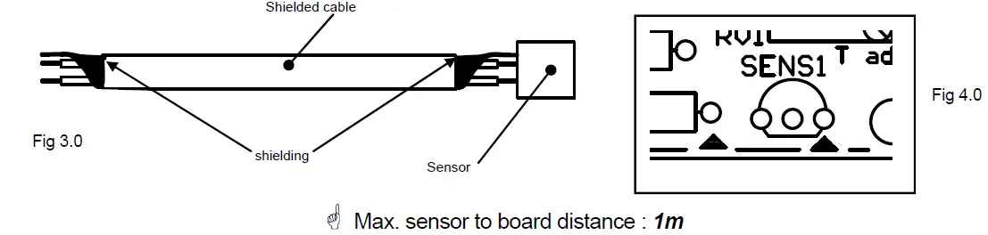
Remote location
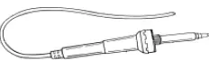
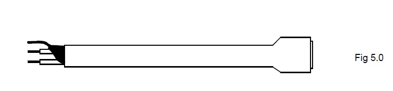
- Use shielded cable (3.0) and connect the shielding to the ground (sensor pin marked with an arrow on the PCB,

- Sensor and PCB must be shielded from moisture at all times. Use shrink tube or resin to protect sensor,

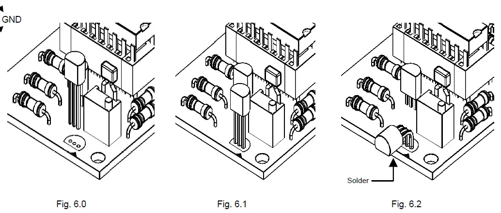
Onboard
Follow the steps displayed in figures 6.0 through 6.2 if you want to mount the sensor directly on the PCB. Solder now the connections of the sensor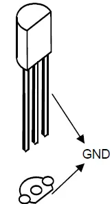
Connection to interface card or application:
Most applications require 0..5V or 0..10V. Put a resistor between the interface input and ground to convert the current to voltage. To calculate the resistor value, divide the max. desired voltage (e.g. 5V) by 0.02. The result is the required resistor value in ohms. In this example : 5/0.02 = 250 ohm (4 x 1K ohm resistor in parallel). 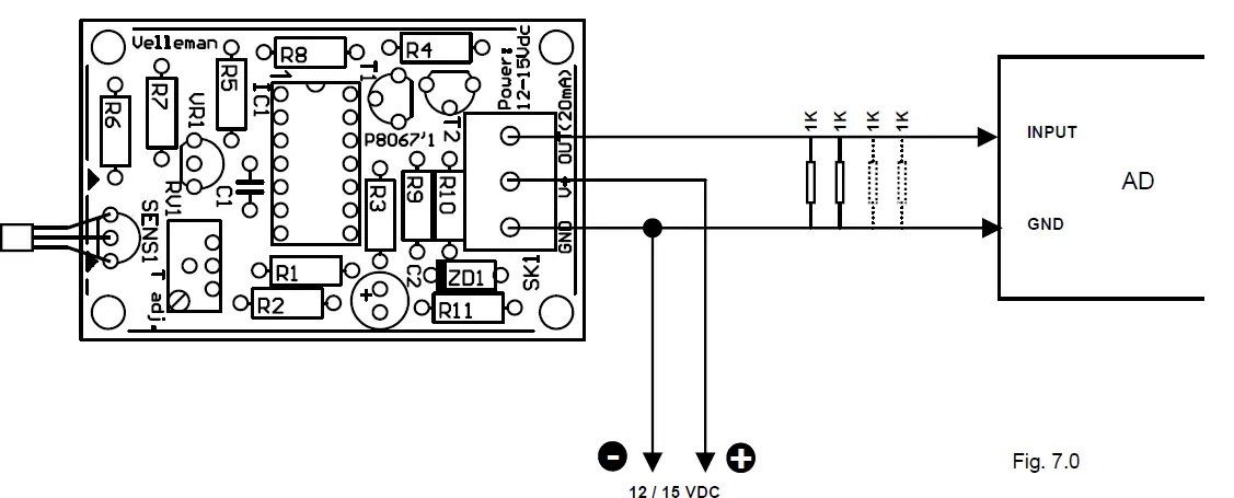
Software
Our website ‘www.velleman.be’ features example software written in VB6. Source code is supplied. Use the source code as a guide to write your own applications. The following formula converts the value returned by the AD converter to °C: °C = (101 * AD-value / 256) – 23 ‘256’ is a value used with an 8-bit AD-converter. For a 10-bit converter, use ‘1024’
Calibration
Connect the sensor to the interface board and apply power to the sensor board. Leave it idle for at least 15 minutes, to allow it to adapt to ambient temperature and put a reliable thermometer next to the sensor. Run your software or the test software. Adjust ‘T adj’ on the K8067 board until the displayed temperature corresponds with the thermometer indication. If you cannot run the software at the time of calibration, follow these steps:
- Connect a 500 ohm resistor (2 x 1K in parallel) between GND and OUT.
- Apply power to the board (15VDC).
- Leave it idle for at least 15 minutes, to allow it to adapt to the ambient temperature and put a reliable thermometer next to the sensor.
- Read the temperature. Divide the readout by 100 (e.g. 25.6°C = 0.256)
- Add 0.23 (0.256 + 0.23 = 0.486).
- Multiply the result by 10 (0.486 x 10 = 4.86).
- Measure the voltage over the 500 ohm resistor with a voltmeter.
- Adjust trimmer ‘T adj’ until you measure the calculated voltage (e.g. 4.86V).
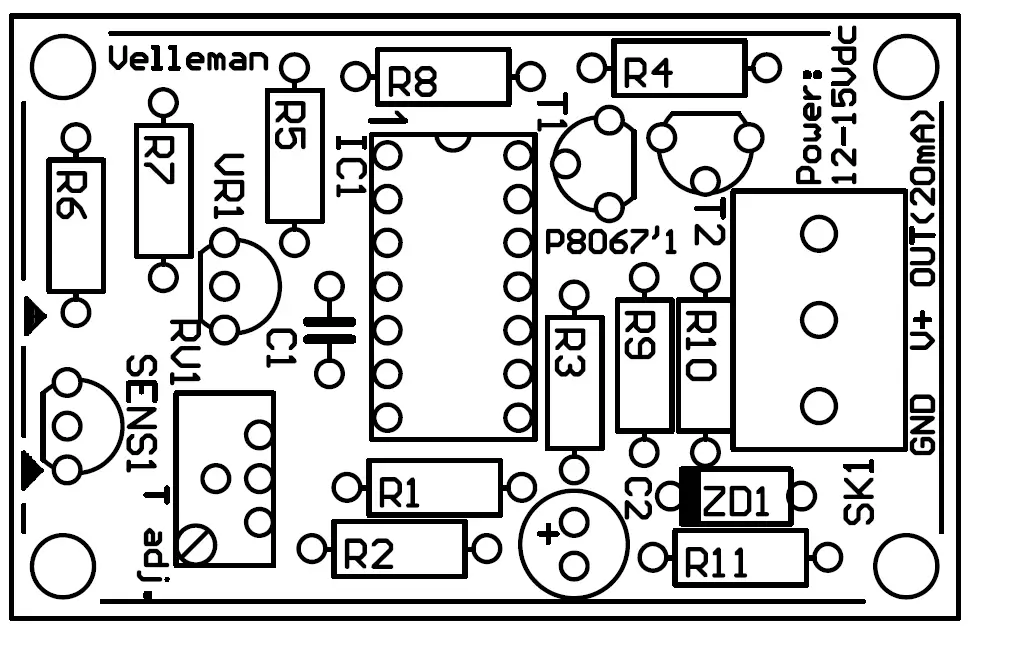
PCB layout.
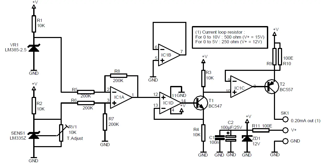
Diagram
- VELLEMAN NV
- Legen Heirweg 33, B-9890 GAVERE
- Belgium (Europe)


