STMicroelectronics UM2963 STEVAL-CTM012V1 Evaluation Board
Getting started with the STEVAL-CTM012V1 evaluation board for 250 W mainstream compressors
Introduction
The STEVAL-CTM012V1 evaluation board is a three-phase inverter based on the STSPIN32F0601Q controller, which embeds a 3-phase 600 V gate driver and an Arm® Cortex®-M0 STM32 MCU.
The power stage features STD8N60DM2 MOSFETs.
The board supports both one-shunt and two- plus one-shunt sensing topology. You can set the shunt topology by opportunely populating a set of jumpers.
Moreover, you can implement a sensor less field-oriented control (FOC). This allows driving permanent magnet synchronous motors (PMSMs) and brushless DC (BLDC) motors to cover a wide range of applications, such as refrigerator compressors, pumps, fans, and industrial appliances.
The STEVAL-CTM012V1 evaluation board is compatible with a wide range of input voltages. It includes a power supply stage with the VIPER122 in buck configuration that generates +15 V and +3.3 V supply voltages required by the application.
The companion firmware is X-CUBE-MCSDK, available for download on www.st.com.
You can compile, debug, and configure the firmware through the STM32CubeIDE and B-STLINK-ISOL plus STLINK-V3SET.
SWD and UART TX-RX connectors are also available.
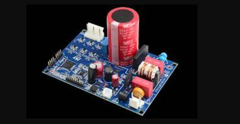
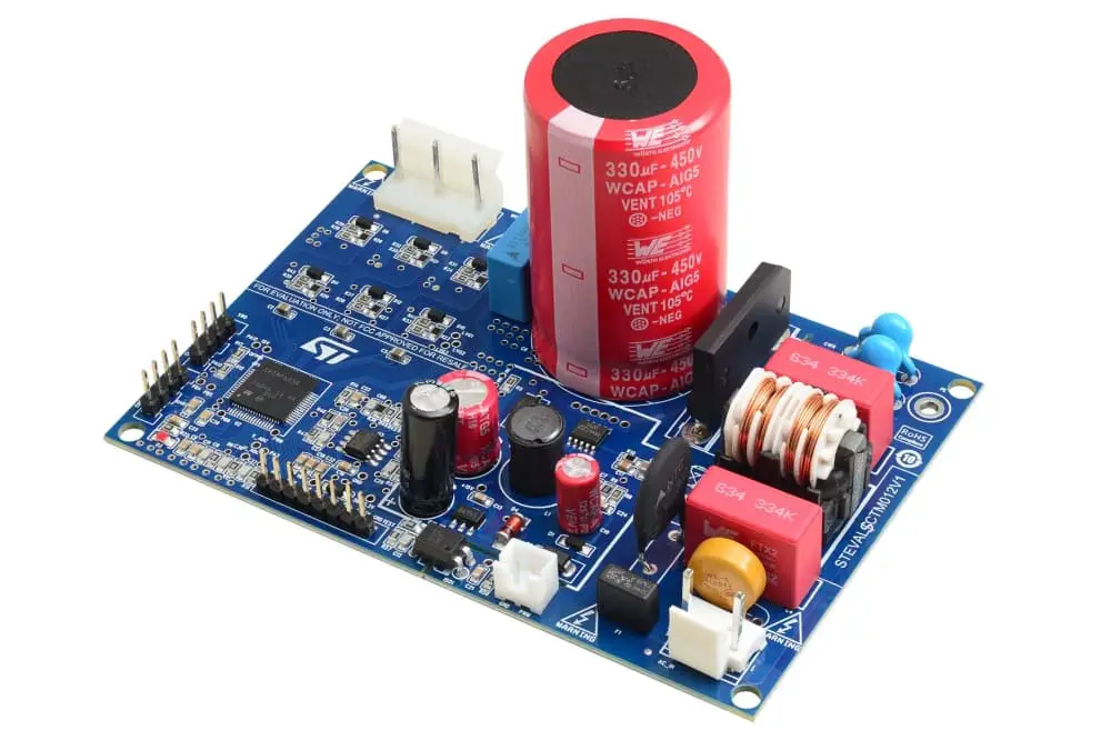
Figure 1. STEVAL-CTM012V1 evaluation board
Getting started
Safety and operating instructions
General terms
Warning: During assembly, testing, and normal operation, the evaluation board poses several inherent hazards, including bare wires, moving or rotating parts, and hot surfaces. There is danger of serious personal injury and damage to property if you improperly use or incorrectly install the board or its components. The board is not electrically isolated from the AC-DC input. The evaluation board is directly linked to the mains voltage. No insulation is ensured between the accessible parts and the high voltage. All measuring equipment must be isolated from the mains before powering the board. When using an oscilloscope with the demo, it must be isolated from the AC line. This prevents shock that derives from touching any single point in the circuit, but does not prevent shock when touching two or more points in the circuit.
All operations involving transportation, installation, and use, as well as maintenance, have to be carried out by skilled technical personnel (national accident prevention rules must be observed). For the purpose of these basic safety instructions, “skilled technical personnel” are considered as suitably qualified people who are familiar with the installation, use, and maintenance of power electronic systems.
Intended use of the board
The STEVAL-CTM012V1 evaluation board is designed for evaluation purposes only and must not be used for electrical installations or machinery.
The documentation details technical data and information about the power supply conditions that have to be strictly observed.
Evaluation board installation
- The installation and cooling of the evaluation board must be in accordance with the specifications and target applications.
- The motor drive converters must be protected against excessive strain. In particular, components should not be bent, or isolating distances altered during transportation or handling.
- No contact must be made with other electronic components and contacts.
- The board contains electrostatically sensitive components that are prone to damage if used incorrectly. Do not mechanically damage or destroy the electrical components (potential health risks).
Evaluation board operation
NOTE: Do not touch the evaluation board after it has been disconnected from the voltage supply as several parts and power terminals containing potentially energized capacitors need time to discharge.
A system architecture that supplies power to the STEVAL-CTM012V1 evaluation board must be equipped with additional control and protective devices in accordance with the applicable safety requirements (that is, compliance with technical equipment and accident prevention rules).
CAUTION: Follow the safety recommendations to operate the board. Use proper PPE, such as protective shields and glasses to avoid injuries due to malfunctions.
Features
- Complete system solution made by ready-to-use hardware and firmware
- Fitting wide range of applications supplied from the mains, rated up to 250 W:
- refrigerator compressors
- pumps and fans
- Industrial appliances
- Very low stand-by power consumption and overcurrent/undervoltage protections
- Based on STSPIN32F0601Q intelligent 3-phase motor controller with embedded STM32
- STD8N60DM2 MOSFETs
- Inverter power stage based on STGD5H60DF IGBT rated 600 V and 5 A
- Compact size: 7.5 x 11.2 cm
- Equipped with proven sensorless field-oriented control (FOC) firmware in one-shunt or 2+1 shunt topology
- RoHS compliant
Target applications
- Three-phase motor drivers
- Fans
- Pumps
- Refrigerator compressors
- Industrial appliances
- Inverters
Hardware and software requirements
To use the STEVAL-CTM012V1 evaluation board, you need the following software and hardware:
- A Windows PC (XP, Vista, Win 7, Win 8, or Win 10) to install the software package;
- B-STLINK-ISOL plus STLINK-V3SET;
- An isolated USB-to-UART wire to connect the board to the PC (optional);
- X-CUBE-MCSDK (v5.3 or later);
- STM32CubeMX (v4.24.0 or later);
- A three-phase brushless PMSM DC motor with compatible voltage and current ratings;
- AC mains power supply or external DC power supply
- Any of the supported IDEs:
- IAR Embedded Workbench® for Arm® (v7.80.4)
- Keil® MDK tools (v5.24.2 or later)
- Ac6 System Workbench (v2.3.0 or later)
- STM32CubeIDE
Hardware description and configuration
Board components
The figures below show the position of the main circuitry blocks of the board.
Figure 2. STEVAL-CTM012V1 main components (top view)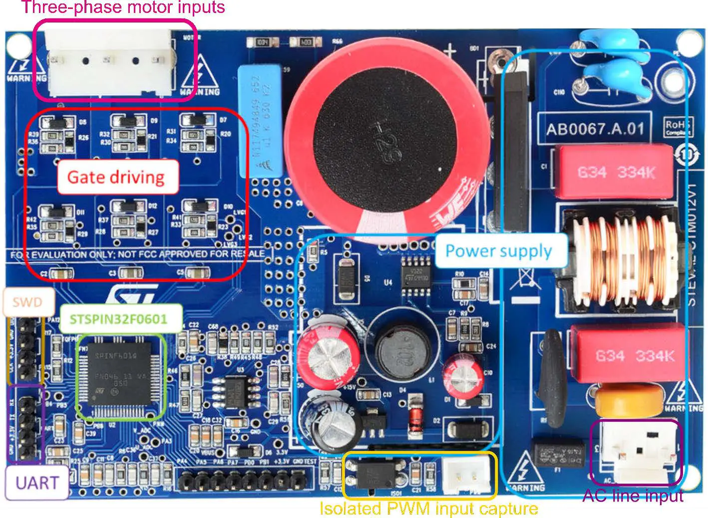 Figure 3. STEVAL-CTM012V1 main components (bottom view)
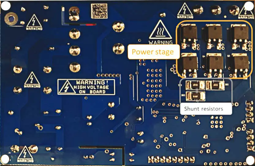
Shunt resistor configuration
You can configure the shunt resistors according to the desired operation:
- SR1 = 0 Ω and SR2 = 0 Ω to operate in single shunt mode set by SR3 value = 0.1 ohm (default configuration);
- Two-shunt plus one-shunt mode by setting:
- SR1 and SR2 to the desired value (that is SR1=0.1 Ω and SR2= 0.1 Ω);
- SR1: shunt for U phase current sensing;
- SR2: shunt for V phase current sensing;
- SR3: shunt for overcurrent protection.
Figure 4. STEVAL-CTM012V1 – shunt configuration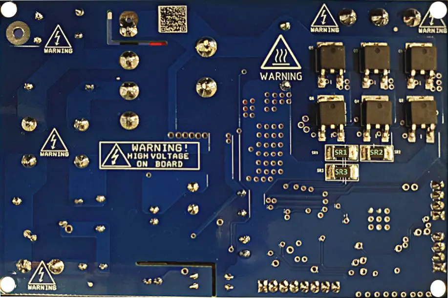
Overcurrent detection and current-sensing measurement
The STEVAL-CTM012V1 evaluation board implements overcurrent protection based on the STSPIN32F0601Q integrated comparator.
The SR3 shunt resistor measures the load current that brings the voltage signal to the CIN pin. When the phase peak current exceeds the selected threshold, the integrated comparator is triggered and all the power switches
are disabled. Power switches are enabled again when the current falls below the threshold and the output disable time expires, thus implementing a current limitation control.
By default, the evaluation board has an overcurrent threshold set to IOC_typ= 4.6 A and a restart time after fault detection of ~28 µs. You can change these values by changing SR3, C18, and R14.
Bus voltage circuit
The STEVAL-CTM012V1 evaluation board features bus voltage sensing.
You can set this signal through a voltage divider from the motor supply voltage (VBUS – R65, R66, and R5) and send it to the PA0 GPIO (ADC channel 0) of the embedded MCU. The input voltage is then downsized of a 200x factor.
Firmware debug
The “STEVAL-CTM01xV1 1shunt_FOC” folder contains a reference firmware generated for IAR v8.5. It works on the evaluation board with one shunt resistor (default configuration).
You can download the firmware through the SWD port as described in 5.
You can also generate the firmware and download it on the MCU through the SWD port.
The diagram below shows the workflow of the firmware generation and application debug process.
Figure 5. STEVAL-CTM012V1 – X-CUBE-MCSDK workflow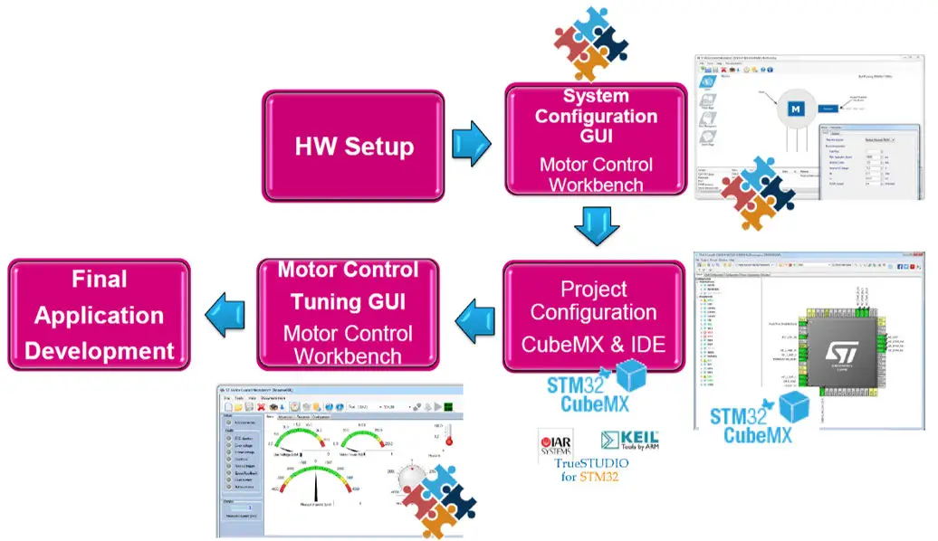
Note: To generate the firmware by using X-CUBE-MCSDK, follow the procedure below.
In this example, we use X-CUBE-MCSDK version 5.4.4, but you can use later versions, too.
Step 1. Launch X-CUBE-MCSDK.
Step 2. To start with an environment already set for the evaluation board, load the configuration file provided with the firmware package, named “STEVAL-CTM01xV1 1shunt_FOC.stmcx”.
Step 2a. Choose [Load Project] and select the file.
Step 2b. Alternatively, create a new project by selecting [New Project]>[Inverter]>[Custom board] and follow the next steps.
Step 3. Configure the motor parameters, start-up sequence, and all the relevant parameters according to the target application, as per the user manual in [Documentation]>[’Getting started with STM32 motor control SDK v5.x’].
Figure 6. X-CUBE-MCSDK configuration options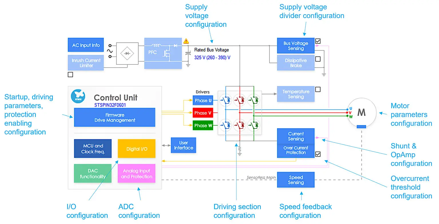
Figure 7. X-CUBE-MCSDK configuration example (1 of 2)
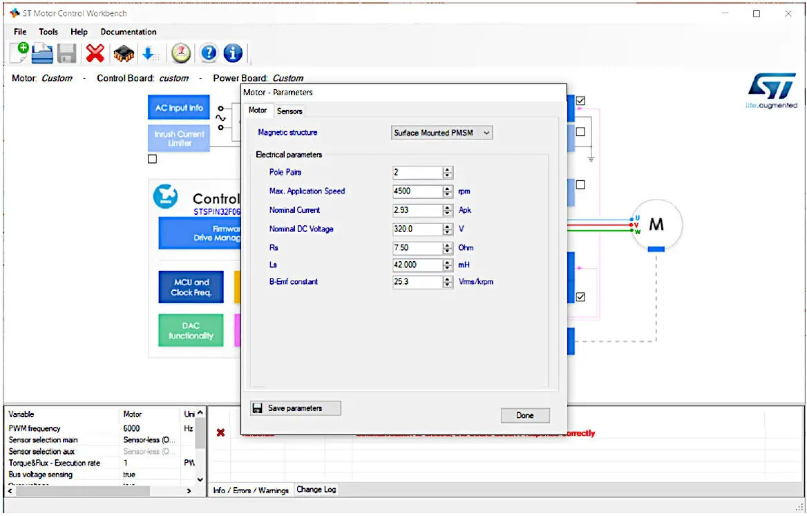
Figure 8. X-CUBE-MCSDK configuration example (2 of 2)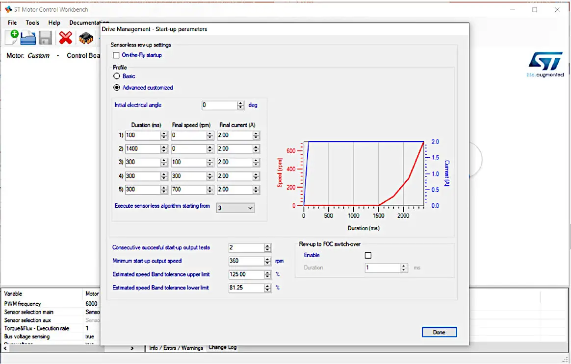 Step 4. Click on the generate icon.
You can then generate the project according to your selected IDE environment.
The X-CUBE-MCSDK motor control workbench calls the STM32CubeMX in background to generate the project frame in the selected IDE.
When the firmware generation starts, a progress window shows that the script is running. When finished, the tip window appears. The user information table is updated accordingly.
Figure 9. X-CUBE-MCSDK firmware generation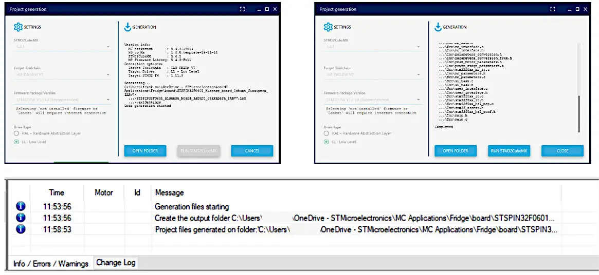 Step 5. After project generation, open the project file, compile, and download it onto the STSPIN32F0601Q device.
Figure 10. Project opened in the selected IDE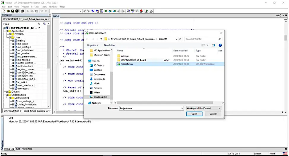
Figure 11. Project compiled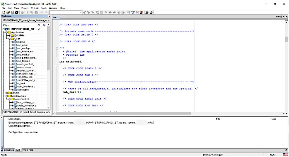
How to use the board
To start your project with the STEVAL-CTM012V1 evaluation board:
Step 1. Connect the motor to the CON_UVW connector.
Important: Pay attention to the motor phase sequence.
Step 2. Supply the evaluation board through the AC_IN AC mains connector.
Step 3. Develop your application using the STM32 FOC MC library.
Schematic diagrams
Figure 12. STEVAL-CTM012V1 circuit schematic (1 of 2)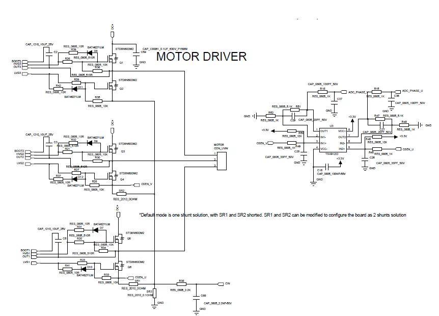
Figure 13. STEVAL-CTM012V1 circuit schematic (2 of 2)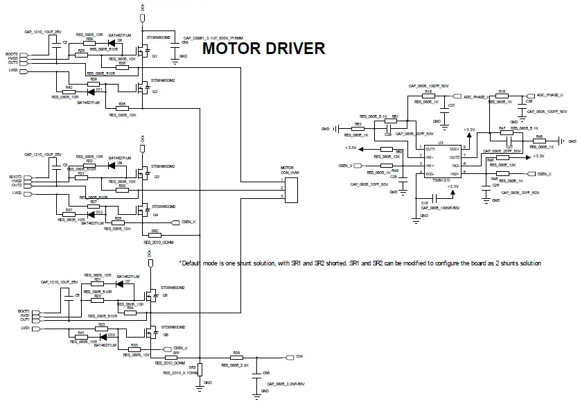
Bill of materials
Table 1. STEVAL-CTM012V1 bill of materials
| Item | Q.ty | Ref. | Part/Value | Description | Manufacturer | Order code |
|
1 |
8 |
D1, D6, D7-12 |
BAT46ZFILM, SOD-123 | 100 V, 150 mA SMD general- purpose signal Schottky diode |
ST |
|
| 2 | 1 | C17 | 0805, 1.2 nF, 50 V, ±10% | Capacitor | Kyocera AVX | 08055C122K4T2A |
| 3 | 12 | C7, C9, C11, C13, C16, C20, C22-25, C32, C39 | 0805, 50 V, ±10% | Capacitors | Wurth Elektronik | 885012207098 |
| 4 | 3 | C8, C36-37 | 150 pF, 0805, 50 V, ±10%, C0G/NP0 | Ceramic capacitors | Wurth Elektronik | 885012007058 |
| 5 | 2 | C18, C21 | 0805, 10 nF, 50 V, ±10% | Capacitors | Wurth Elektronik | 885012207092 |
| 6 | 1 | C12 | 1500 pF, 0805, 50 V, C0G/NP0 | Ceramic capacitor | Wurth Elektronik | 885012007064 |
| 7 | 1 | C68 | 0805, 2.2 nF, 50 V, ±10% | Capacitor | Wurth Elektronik | 885012007065 |
| 8 | 2 | C27, C29 | 0805, 20 pF, 50 V, ±5% | Capacitors | KEMET | C0805X200J5GACTU |
| 9 | 2 | C26, C28 | 0805, 33 pF, 50 V, ±5% | Capacitors | Kyocera AVX | 08055C330JAT2A |
| 10 | 1 | C14 | 0805, 470 nF, 50 V, ±10% | Capacitor | Taiyo Yuden | UMK212C7474KGHTE |
| 11 | 3 | C2-C3, C5 | 10 µF, 0805, 25 V | Ceramic capacitors | Taiyo Yuden | TMK212BBJ106KG-T |
| 12 | 1 | C59 | CBB61, 0.1 µF, 630 V, through-hole, P = 15 mm 630 V, ±10% | Capacitor | Panasonic | ECQ-E6104KFA |
| 13 | 2 | C109-110 | CC, Y1, 471, 250 V, through-hole, P = 7.5 mm, 250 VAC, ±10% | Capacitors | Panasonic | ECW-F2474JAB |
| 14 | 1 | C10 | 10 µF, Ø5*L11, 50 V, ± 20% | Capacitor | Wurth Elektronik | 860130673001 |
| 15 | 1 | C15 | EC, 330 µF, 35 V Ø10*L12.5 | Capacitor | Wurth Elektronik | 860020575013 |
| 16 | 1 | C6 | EC, 330 µF, 450 V Ø30*L51 | Capacitor | Wurth Elektronik | 861021485026 |
| 17 | 1 | C19 | 470 µF, Ø8*L122, 35 V, ±20% | Aluminum capacitor | Panasonic | EEU-FR1V471L |
| 18 | 2 | C1, C4 | 0.33 µF, 275 VAC, pitch 15 mm | Film capacitors | Wurth Elektronik | 890324025034CS |
| 19 | 1 | AC_IN | CON_2PINA, P =7.92 mm | Connector header | Molex | 0359790210 |
| 20 | 1 | JP3 | CON_2PIN_B2B, Through hole,P=2.5mm | Connector header | Samtec | TSW-101-07-F-D |
| 21 | 2 | SWD UART | CON_4PIN, through hole,P=2.54mm | Header spacer connector | Amphenol | 75970-3BB-04LF |
| 22 | 1 | TEST | CON_8PIN, through hole,P=2.54mm | Connector header | Amphenol | 78511-408HLF |
| 23 | 1 | MOTOR | CON_UVW, through hole | Connector header | Molex | 0010634037 |
| 24 | 1 | D4 | DIOZ_1N4745A, 16V, 1W, LL-41 | Zener diode | Vishay Semiconductor Diodes Division | ZM4745A-GS08 |
| 25 | 1 | BD1 | DIO_DB_KBJ608, KBJ | Bridge rectifier | Diodes Incorporated | KBJ608G |
| 26 | 1 | D3 | DIO_LED, 0805 | Red LED | Visual Communicatio ns Company – VCC | CMD17-21VRD/TR8 |
| 27 | 1 | F1 | FUSE_T3.15A-250 VAC through hole,P=5.08mm 250V | Fuse | Bel Fuse Inc. | RST 3.15-BULK |
| 28 | 1 | L1 | 1 mH 800 mA 1.15 ohm, pitch 5 mm | Fixed inductor | Wurth Elektronik | 7447480102 |
| 29 | 1 | L2 | CMC 3.9 mH 1 A 2LN TH | Common mode choke | Wurth Elektronik | 7448640412 |
| 30 | 1 | U6 | L78L33ACUTR | Positive voltage regulator | ST | L78L33ACUTR |
| 31 | 1 | RV1 | MOV_681 | High surge varactor | Wurth Electronic | 820415511B |
| 32 | 1 | R1 | NTC_5D15, through-hole, P = 7.5 mm, 5 Ω ±20% | Thermistor | EPCOS – T Electronics | B57234S0509M051 |
| 33 | 1 | ISO1 | PC817, DIP-4 | opt isolator transistor | Taiwan Semiconductor Corporation | TPC817C C9G |
| 34 | 6 | R31-32, R37, R39, R41-42 | RES_0805_10R, 0805, 10.0 Ω (10R0) ±1% | Resistors | Rohm | SFR10EZPF10R0 |
| 35 | 4 | R12, R17, R57-58 | RES_0805_220R, 0805, 220.0 Ω(10R0) ±1% | Resistors | Rohm | KTR10EZPF2200 |
| 36 | 6 | R20-21, R23, R26-27, R29 | RES_0805_510R, 0805, 510 Ω ±1% | Resistors | Rohm | KTR10EZPF5100 |
| 37 | 8 | R5, R14, R28, R30, R33-36 | RES_0805_10K, 0805, 10 kΩ ±1% | Resistors | Rohm | SFR10EZPF1002 |
| 38 | 2 | R46, R50 | RES_0805_12K, 0805, 12 kΩ ±1% | Resistors | Rohm | KTR10EZPF1202 |
| 39 | 1 | R10 | RES_0805_17.4K, 0805, 17.4 kΩ ±1% | Resistor | Rohm | KTR10EZPF1742 |
| 40 | 9 | R6, R15-16, R25, R45, R48-49, R52, R60 | RES_0805_1K, 0805, 1 kΩ ±1% | Resistors | Rohm | KTR10EZPF1001 |
| 41 | 1 | R38 | RES_0805_2.2K, 0805, 2.2 kΩ ±1% | Resistor | Rohm | SFR10EZPF2201 |
| 42 | 1 | R8 | RES_0805_33K, 0805, 33 kΩ ±1% | Resistor | Rohm | KTR10EZPF3302 |
| 43 | 2 | R47, R51 | RES_0805_5.1K, 0805, 5.1 kΩ ±1% | Resistors | Rohm | SFR10EZPF5101 |
| 44 | 1 | R9 | RES_0805_9.1K, 0805, 9.1 kΩ ±1% | Resistor | Rohm | SFR10EZPF9101 |
| 45 | 2 | R65-66 | RES_1206_1M, 1206, 1 mΩ ±1% | Resistors | Rohm | KTR18EZPF1004 |
| 46 | 2 | SR3 | RES_2010_0.1 ohm 2010 0.1 Ω ±1% | Resistor | Vishay | WFMB2010R1000FEA |
| 47 | 1 | SR1-SR2 | RES_2010_0OHM, 2010, 0 Ω | Resistors | Vishay | CRCW20100000Z0EFHP |
| 48 | 6 | Q1-6 | STD8N60DM2, DPAK | N-channel 600 V, 550 mOhm typ., 8 A MDmesh DM2 power MOSFET in a DPAK package | ST | STD8N60DM2 |
| 49 | 1 | U2 | STSPIN32F0601Q, TQFP 10×10 64PIN/ QFN10x10 72PIN | 600 V three- phase controller with MCU | ST | STSPIN32F0601Q |
| 50 | 2 | D2 D5 | STTH1L06A, SOD-123F | 600 V, 1 A low drop ultrafast diode | ST | STTH1L06A |
| 51 | 1 | U3 | TSV912ID, SO8 | Wide bandwidth (8MHz) rail- to-rail input/ output 5 V CMOS op- amp | ST | TSV912ID |
| 52 | 1 | U4 | VIPER122, SSOP10 | High-voltage converter | ST | VIPER122 |
| 53 | 1 | PCB | 113x76x1.6mm | FR4 TG 140, CU thickness 35 microns | Any | Any |
Board versions
Table 2. STEVAL-CTM012V1 versions
| Finished good | Schematic diagrams | Bill of materials |
| STEVAL$CTM012V1A (1) | STEVAL$CTM012V1A schematic diagrams | STEVAL$CTM012V1A bill of materials |
- This code identifies the STEVAL-CTM012V1 evaluation board first version.
References
- STSPIN32F0601Q datasheet
- UM2380: “STM32 motor control SDK v5.x tools”
- UM1718: “STM32CubeMX for STM32 configuration and initialization C code generation”
- UM0892: “STM32 ST-LINK utility software description”
Revision history
Table 3. Document revision history
| Date | Revision | Changes |
| 13-Jan-2022 | 1 | Initial release. |
| 07-Feb-2022 | 2 | Updated Section 1.1.4 Evaluation board operation. |
| 05-May-2022 | 3 | Updated introduction. |
IMPORTANT NOTICE – READ CAREFULLY
STMicroelectronics NV and its subsidiaries (“ST”) reserve the right to make changes, corrections, enhancements, modifications, and improvements to ST products and/or to this document at any time without notice. Purchasers should obtain the latest relevant information on ST products before placing orders. ST products are sold pursuant to ST’s terms and conditions of sale in place at the time of order acknowledgment.
Purchasers are solely responsible for the choice, selection, and use of ST products and ST assumes no liability for application assistance or the design of purchasers’ products.
No license, express or implied, to any intellectual property right is granted by ST herein.
Resale of ST products with provisions different from the information set forth herein shall void any warranty granted by ST for such product.
ST and the ST logo are trademarks of ST. For additional information about ST trademarks, refer to www.st.com/trademarks. All other product or service names are the property of their respective owners.
Information in this document supersedes and replaces information previously supplied in any prior versions of this document.
© 2022 STMicroelectronics – All rights reserved


