EBYTE E49-400M20S 470MHz SMD Module User Manual
Overview
Brief Introduction
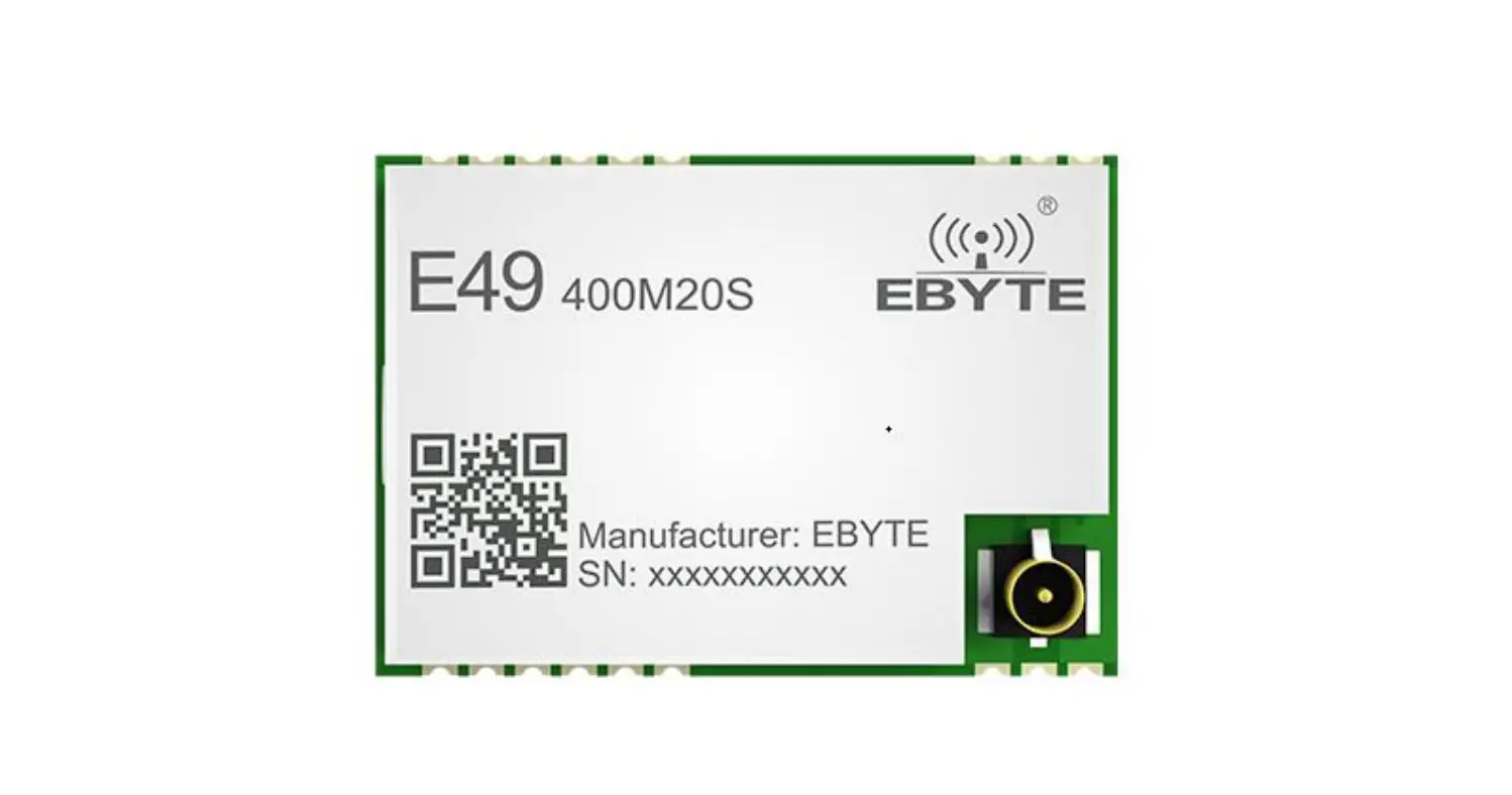
E49-400M20S is a cost-effective wireless data transmission module launched by Chengdu Ebyte. It is a pure hardware module based on CMT2300A. E49 400M20S supports a maximum transmit power of 20dBm, and users can set a lower output power to save power consumption. The module works in the 410MHz ~ 510MHz frequency band, covering the commonly used 433MHz and 470MHz frequency bands. Since this module is a pure RF transceiver module, it uses an SPI interface and requires an MCU driver.
Key Features
- The measured communication distance can reach 2.5km;
- The maximum transmit power is 20dBm, and the software can be adjusted in multiple levels;
- Support ISM 433MHz/470MHz frequency band;
- Support data transmission rate from 0.5Kbps to 300Kbps;
- Support low power consumption mode, suitable for battery applications;
- Support GFSK modulation and OOK and (G)MSK;
- Support 2.6V~3.6V power supply;
- Industrial grade standard design, support long-term use at -40~85℃;
- Support stamp hole and IPEX interface, users can choose to use according to their own needs.
Application
- Smart home and industrial sensors, etc.;
- Security system, positioning system;
- Wireless remote control, UAV;
- Wireless game remote control;
- Healthcare products;
- Wireless voice, wireless headset;
- Automotive industry applications
Specification and Parameter
Limit parameter
Table 2-1 Limit parameter table
| Main parameter | Performance | Remark | |
| Min. | Max. | ||
| Power supply (V) | 0 | 3.6 | Voltage over 3.6V will cause permanent damage to module |
| Operating temperature(℃) | -40 | 85 | / |
Working Parameters
Table 2-2 Limit parameter table
| Main parameter | Performance | Remark | |||
| Min. | Typ. | Max. | |||
| Operating voltage) | 1.8 | 3.3 | 3.6 | Over 3.6V may permanently burn the module | |
| Communication level) | – | 3.3 | – | Using 5V level has the risk of burning | |
| Operating temperature(℃) | -40 | – | +85 | Industrial grade | |
| Operating frequency MHz) | 410 | 433 | 510 | – | |
| Power consumption | TX current (mA) | – | 85 | @Transmit power 20dBm | Instant power consumption |
| RX current (mA) | – | 8.5 | – | ||
| Sleep current (μA) | – | 0.1 | – | Software is shut down | |
| Max Tx power (dBm) | – | 20 | – | – | |
| Receiving sensitivity (dBm) | -116 | -117 | -118 | @Air rate is 1.2kbps | |
| Main parameter | Description | Remark |
| Reference distance | 2.5km | Clear and open, antenna height 2.5 meters, air rate 2.4kbps |
| Crystal frequency | 26MHz | – |
| Packaging method | SMD | – |
| Communication Interface | SPI | – |
| Dimensions | 20*14mm | – |
| RF interface | IPEX/stamp hole | Equivalent impedance is about 50Ω |
| product weight | 1.2±0.1g | Clear and open, antenna height 2.5 meters, air rate 2.4kbps |
Size and pin definition
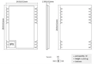
Image 3-1 Mechanical Dimensions and Pin Definition
Chart 3-1 Pin definition table
| No. | Name | Direction | Function |
| 1 | GND | – | Ground wire, connect to power reference ground |
| 2 | GND | – | Ground wire, connect to power reference ground |
| 3 | GND | – | Ground wire, connect to power reference ground |
| 4 | GND | – | Ground wire, connect to power reference ground |
| 5 | GPIO1 | DI/O | Configurable multi-function IO port (see CMT2300A manual for details) |
| 6 | GPIO2 | DI/O | Configurable multi-function IO port (see CMT2300A manual for details) |
| 7 | GPIO3 | DI/O | Configurable multi-function IO port (see CMT2300A manual for details) |
| 8 | VCC | – | Module power supply, connect to power supply +3.3V |
| 9 | GND | – | Ground wire, connect to power reference ground |
| 10 | GND | – | Ground wire, connect to power reference ground |
| 11 | SCLK | DI | SPI clock pin |
| 12 | SDIO | DI/O | SPI data pins |
| 13 | CSB | DI | Chip select for SPI access register |
| 14 | FCSB | DI | Chip select for SPI access to FIFO |
| 15 | GND | – | Ground wire, connect to power reference ground |
| 16 | GND | – | Ground wire, connect to power reference ground |
| 17 | ANT | – | Module RF stamp hole interface, equivalent impedance is about 50Ω |
| 18 | GND | – | Ground wire, connect to power reference ground |
Hardware and Software Notice
Hardware Notice
- It is recommended to use a DC stabilized power supply to supply power to the module. The power supply ripple coefficient is as small as possible, and the module needs to be reliably grounded
- Please pay attention to the correct connection of the positive and negative poles of the power supply, such as reverse connection may cause permanent damage to the module;
- Please check the power supply to ensure that it is between the recommended power supply voltage, if exceeding the maximum value will cause permanent damage to the module;
- Please check the power supply stability, the voltage cannot fluctuate significantly and frequently;
- When designing the power supply circuit for the module, it is often recommended to reserve more than 30%of the margin, so that the whole machine is conducive to long-term stable work;
- The module should be as far away as possible from the power supply, transformer, high-frequency wiring and other parts with large electromagnetic interference;
- High-frequency digital traces, high-frequency analog traces, and power traces must be avoided under the module. If it is absolutely necessary to pass under the module, it is assumed that the module is soldered to the Top Layer, and copper is laid on the Top Layer of the module contact part (all copper And well grounded), must be close to the digital part of the module and the wiring is on the Bottom Layer;
- Assuming that the module is soldered or placed on the Top Layer, it is also wrong to randomly route on the Bottom Layer or other layers, which will affect the module’s spurs and receiving sensitivity to varying degrees;
- It is assumed that there are devices with large electromagnetic interference around the module that will greatly affect the performance of the module. It is recommended to stay away from the module according to the intensity of the interference. If the situation permits, proper isolation and shielding can be done;
- It is assumed that there are traces with high electromagnetic interference around the module (high-frequency digital, high-frequency analog, and power traces), which will greatly affect the performance of the module. It is recommended to stay away from the module according to the intensity of the interference. Isolation and shielding;
- Try to stay away from the TTL protocol which is also 2.4GHz in some physical layers, for example: USB3.0;
- The antenna installation structure has a great impact on the performance of the module. Make sure that the antenna is exposed, preferably vertically. When the module is installed inside the chassis, you can use high-quality antenna extension cords to extend the antenna to the outside of the chassis;
- The antenna must not be installed inside the metal shell, which will greatly weaken the transmission distance.
Software Notice
- The chip of this module is CMT2300A, and its driving mode is SPI, and users can operate according to the CMT2300AchipDatasheet.
- GPIO1/GPIO2/GPIO3 are general-purpose I/O ports, see CMT2300A Datasheet for details.
Basic Circuit Diagram
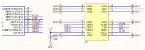
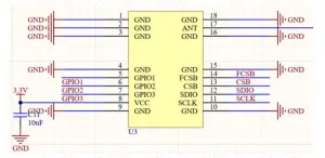
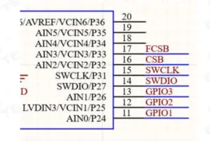
Chart 5-1 circuit diagram
FAQ
Communication range is too short
- The communication distance will be affected when obstacle exists.
- Data lose rate will be affected by temperature, humidity and co-channel interference.
- The ground will absorb and reflect wireless radio wave, so the performance will be poor when testing near ground.
- Sea water has great ability in absorbing wireless radio wave, so performance will be poor when testing near the sea.
- The signal will be affected when the antenna is near metal object or put in a metal case.
- Power register was set incorrectly, air data rate is set as too high (the higher the air data rate, the shorter the distance).
- The power supply low voltage under room temperature is lower than 2.5V, the lower the voltage, the lower the transmitting power.
- Due to antenna quality or poor matching between antenna and module.
Module is easy to damage
- Please check the power supply source, ensure it is 2.0V~3.6V, voltage higher than 3.6V will damage the module.
- Please check the stability of power source, the voltage cannot fluctuate too much.
- Please make sure antistatic measure are taken when installing and using, high frequency devices have electrostatic susceptibility.
- Please ensure the humidity is within limited range, some parts are sensitive to humidity.
- Please avoid using modules under too high or too low temperature.
BER(Bit Error Rate) is high
- There are co-channel signal interference nearby, please be away from interference sources or modify frequency and channel to avoid interference;
- Poor power supply may cause messy code. Make sure that the power supply is reliable.
- The extension line and feeder quality are poor or too long, so the bit error rate is high;
Guide for Soldering work
Reflow soldering temperature
| Profile Feature | Curve characteristics | Sn-Pb Assembly | Pb-Free Assembly |
| Solder Paste | Solder paste | Sn63/Pb37 | Sn96.5/Ag3/Cu0.5 |
| Preheat Temperature min (Tsmin) | Min preheating temp. | 100℃ | 150℃ |
| Preheat temperature max (Tsmax) | Mx preheating temp. | 150℃ | 200℃ |
| Preheat Time (Tsmin to Tsmax)(ts) | Preheating time | 60-120 sec | 60-120 sec |
| Average ramp-up rate(Tsmax to Tp) | Average ramp-up rate | 3℃/second max | 3℃/second max |
| Liquidous Temperature (TL) | Liquid phase temp. | 183℃ | 217℃ |
| Time (tL) Maintained Above (TL) | Time below liquid phase line | 60-90 sec | 30-90 sec |
| Peak temperature (Tp) | Peak temp. | 220-235℃ | 230-250℃ |
| Average ramp-down rate (Tp to Tsmax) | Average ramp-down rate | 6℃/second max | 6℃/second max |
| Time 25℃ to peak temperature | Time to peak temperature for 25℃ | max 6 minutes | max 8 minutes |
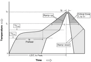
Reflow soldering curve
Similar Products with CMT2300A
| Model | Chip | Freq. | Tx Power | Range | Dim. | Package Type | Interface |
| Hz | dBm | km | mm | ||||
| E49-400T20S | CMT2300A | 410~450MHz | 20 | 1 | 26*16 | SMD | UART |
| E49-400T20D | CMT2300A | 410~450MHz | 20 | 1 | 36*21 | DIP | UART |
Recommendation for Antennas
The antenna is very important for the RF module, and the antenna performance will have a great impact on the communication system. Therefore, we recommend you below antennas which are suitable for Ebyte modules with excellent performance and reasonable price: Please search the model and see more antenna details on: http://www.ebyte.com/en/product-class.aspx?key=TX
| Model | Type | Freq. | Gain | Dim. | Cable Length | Features | |
| Hz | dBi | mm | cm | ||||
| TX433-JW-5 | Rubber antenna | 433M | 2 | 50mm | – | SMA-J | Bendable, omnidirectional |
| TX433-JWG-7 | Rubber antenna | 433M | 2.5 | 75mm | – | SMA-J | Bendable, omnidirectional |
| TX433-JK-20 | Rubber antenna | 433M | 3 | 210mm | – | SMA-J | Bendable, omnidirectional |
| TX433-JK-11 | Rubber antenna | 433M | 2.5 | 110mm | – | SMA-J | Bendable, omnidirectional |
| TX433-XP-200 | Magnetic base antenna | 433M | 4 | 19cm | 200cm | SMA-J | magnet base, high gain |
| TX433-XP-100 | Magnetic base antenna | 433M | 3.5 | 18.5cm | 100cm | SMA-J | magnet base, high gain |
| TX433-XPH-300 | Magnetic base antenna | 433M | 6 | 96.5cm | 300cm | SMA-J | magnet base, ultra high gain |
| TX433-JZG-6 | Rubber antenna | 433M | 2.5 | 52mm | – | SMA-J | Ultra short straight, omnidirectional |
| TX433-JZ-5 | Rubber antenna | 433M | 2 | 52mm | – | SMA-J | Ultra short straight, omnidirectional |
| TX490-XP-100 | Magnetic base antenna | 490M | 50 | 12cm | 100cm | SMA-J | magnet base, high gain |
| TX490-JZ-5 | Rubber antenna | 490M | 50 | 50mm | – | SMA-J | Ultra short straight, omnidirectional |
Revision history
| Version | Date | Remark | By |
| 1.0 | 2020-05-28 | First version | Huaa |
| 1.1 | 2020-11-16 | Parameter correction | Linson |
| 1.2 | 2021-6-10 | Parameter correction | Linson |
| 1.3 | 2021-6-23 | Error correction | Linson |
About us
Technical support: [email protected]
Documents and RF Setting download link: www.ebyte.com
Thank you for using Ebyte products! Please contact us with any questions or suggestions: [email protected]
Fax: 028-64146160
Web: www.ebyte.com
Address: B5 Mould Industrial Park, 199# Xiqu Ave, High tech Zone, Chengdu, Sichuan, China


