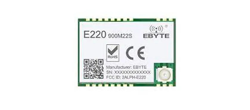
EBYTE E220-900M22S Llcc68 868 915 MHz 160mw SPI SMD Lora Module
Disclaimer
EBYTE reserves all rights to this document and the information contained herein. Products, names, logos and designs described herein may in whole or in part be subject to intellectual property rights. Reproduction, use, modification or disclosure to third parties of this document or any part thereof without the express permission of EBYTE is strictly prohibited. The information contained herein is provided “as is” and EBYTE assumes no liability for the use of the information. No warranty, either express or implied, is given, including but not limited, with respect to the accuracy, correctness, reliability and fitness for a particular purpose of the information. This document may be revised by EBYTE at any time. For most recent documents, visit www.ebyte.com.
Features
- The measured distance can reach 5500m;
- The maximum transmitting power is 160mw, and the software is multi-level adjustable;
- Support global license free ism 868 / 915MHz band;
- In LoRaTM mode, the data transmission rate is 1.76kbps ~ 62.5kbps;
- FSK mode supports up to 300kbps data transmission rate;
- FIFO has large capacity and supports 256 byte data cache;
- Support spread spectrum factor sF5, SF6, sf7, SF8, Sf9, SF10, SF11;
- Support 1.8V ~ 3.7V power supply, more than 3.3V power supply can guarantee the best performance;
- Industrial standard design, support – 40 ~ 85 ° C long-term use;
- Dual RF interface is optional (IPEX / stamp hole), which is convenient for secondary development and integration.
Introduction
Brief Introduction
E220-900m22s is an small module, self-developed based on the new generation of LoRaTM RF chip llcc68, produced by Semtech company. It is suitable for 868mhz and 915MHz LoRaTM wireless module and uses industrial 32mhz crystal oscillator. Compared with the previous generation of LoRaTM transceiver, its anti-jamming performance and communication distance have been further improved. Because of its new LoRaTM modulation technology, its anti-jamming performance and communication distance are far superior to the current FSK and GFSK modulation products. The module is mainly aimed at smart home, wireless meter reading, scientific research and medical and medium and long distance wireless communication equipment. The product can cover a wide frequency range of 850 ~ 930mhz.
Because the module is a pure RF transceiver module, it needs to use MCU driver or special SPI debugging tool.
Application
- Home security alarm and remote keyless entry;
- Smart home and industrial sensors, etc;
- Wireless alarm security system;
- Building automation solutions;
- Wireless industrial remote controller;
- Health care products;
- Advanced meter reading architecture (AMI);
- Automotive industry applications.
Specification and parameter
Limit parameter
| Main parameter | Performance | Remarks | |
| Min | Max | ||
| Supply voltage (V) | 0 | 3.7 | Over 3.7V permanently burned module |
| Blocking power (DBM) | – | 10 | The burning probability is small in close range use |
| Working temperature (℃) | -40 | +85 | Industrial grade |
Operating parameter
| Main parameter | Performance | Remarks | |||
| Min | Type | Max | |||
| Operating voltage(V) | 1.8 | 3.3 | 3.7 | ≥3.3 V ensures output power | |
| Communication level(V) | – | 3.3 | – | For 5V TTL, it may be at risk of burning down | |
| Operating temperature(℃) | -40 | – | 85 | Industrial Design | |
| Operating frequency(MHz) | 850 | 868/915 | 930 | Support ISM band | |
| Power Consump- tion | TX current(mA) | – | 130 | – | Instantaneous power consumption |
| RX current(mA) | – | 6.5 | – | – | |
| Sleep current (μA) | – | 180 | – | Software shutdown | |
| Max TX power(dBm) | 21.4 | 21.5 | 22 | – | |
| Receiving sensitivity(dBm) | – | -129 | – | BW_L=250kHz,SF = 10,LORATM; | |
| Air data rate(bps) | 1.76k | – | 62.5k | Controlled via user’s programming | |
| Main parameter | Description | Remark |
| Reference distance | 5500m | In clear and open environment, the antenna gain is 5dBi, the antenna height is 2.5m, and the air speed is 2.4kbps. |
| FIFO | 256Byte | Maximum length of single transmission |
| Crystal frequency | 32MHz | – |
| Modulation mode | LoRa | Lora modulation is recommended |
| Packaging method | Chip mounted | – |
| Interface mode | Stamp hole | The spacing is 1.27mm |
| Communication interface | SPI | 0-10Mbps |
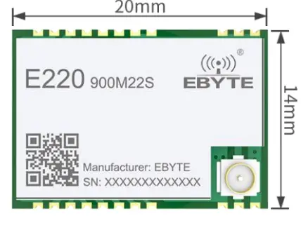
| Dimensions | 20* 14*2.8 mm | Including shield |
| RF interface | Stamp hole / IPEX | – |
Size and pin definition
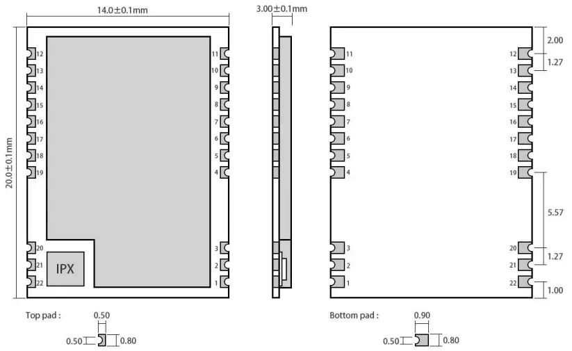
| Pin No. | Item | Direction | Description |
| 1 | GND | Ground, connect to power reference ground | |
| 2 | GND | Ground, connect to power reference ground | |
| 3 | GND | Ground, connect to power reference ground | |
| 4 | GND | Ground, connect to power reference ground | |
| 5 | DIO3 | Configurable universal IO port (see llcc68 manual for details) | |
| 6 | RXEN | input | RF switch receive control pin, connect external MCU IO, high level effective |
| 7 | TXEN | input | RF switch emission control pin, connected to external MCU IO or dio2, high level effective |
| 8 | DIO2 | Input / output | Configurable universal IO port (see llcc68 manual for details) |
| 9 | VCC | Power supply, range 1.8V ~ 3.7V (it is recommended to add ceramic filter capacitor externally) | |
| 10 | GND | Ground, connect to power reference ground | |
| 11 | GND | Ground, connect to power reference ground | |
| 12 | GND | Ground, connect to power reference ground | |
| 13 | DIO1 | Input / output | Configurable universal IO port (see llcc68 manual for details) |
| 14 | BUSY | output | For status indication (see llcc68 manual for details) |
Chengdu Ebyte Electronic Technology Co.,Ltd.
| 15 | NRST | input | Chip reset trigger input pin, low level effective |
| 16 | MISO | output | SPI data output pin |
| 17 | MOSI | input | SPI data input pin |
| 18 | SCK | input | SPI clock input pin |
| 19 | NSS | input | The module chip selection pin is used to start a SPI communication |
| 20 | GND | Ground, connect to power reference ground | |
| 21 | ANT | RF interface, stamp hole | |
| 22 | GND | Ground, connect to power reference ground | |
| For the pin definition, software driver and communication protocol of the module, please refer to the official llcc68 datasheet of Semtech | |||
Basic operation
Hardware design
- It is recommended to use a DC stabilized power supply. The power supply ripple factor is as small as possible and the module needs to be reliably grounded;
- Please pay attention to the correct connection of the positive and negative poles of the power supply,
reverse connection may cause permanent damage to the module; - Please check the power supply to ensure that between the recommended supply voltage, if exceeding the maximum, the module will be permanently damaged;
- Please check the stability of the power supply. Voltage can not fluctuate greatly and frequently;
- When designing the power supply circuit for the module, it is often recommended to reserve more than 30% of the margin, so the whole machine is beneficial for long-term stable operation;
- The module should be as far away as possible from the power supply, transformers, high-frequency wiring and other parts with large electromagnetic interference;
- Bottom LayerHigh-frequency digital routing, high-frequency analog routing, and power routing must be avoided under the module. If it is necessary to pass through the module, assume that the module is soldered to the Top Layer, and the copper is spread on the Top Layer of the module contact part(well grounded), it must be close to the digital part of the module and routed in the Bottom Layer;
- Assuming the module is soldered or placed over the Top Layer, it is wrong to randomly route over the Bottom Layer or other layers, which will affect the module’s spurs and receiving sensitivity to varying degrees;
- It is assumed that there are devices with large electromagnetic interference around the module that will greatly affect the performance. It is recommended to keep them away from the module according to the strength of the interference. If necessary, appropriate isolation and shielding can be done;
- Assume that there are traces with large electromagnetic interference (high-frequency digital, high-frequency analog, power traces) around the module that will greatly affect the performance of the module. It is recommended to stay away from the module according to the strength of the interference.If necessary, appropriate isolation and shielding can be done;
- If the communication line uses a 5V level, a 1k-5.1k resistor must be connected in series (not recommended, there is still a risk of damage);
- Try to stay away from some physical layers such as TTL protocol at 2.4GHz , for example: USB3.0;
- The mounting structure of antenna has a great influence on the performance of the module. It is necessary to ensure that the antenna is exposed, preferably vertically upward. When the module is mounted inside the case, use a good antenna extension cable to extend the antenna to the outside;
- The antenna must not be installed inside the metal case, which will cause the transmission distance to be greatly weakened.
Programming
- This module is llcc68 + peripheral circuit, users can operate according to llcc68 chip book completely;
- Dio1, dio2 and DIO3 are common IO ports, which can be configured into multiple functions. Dio2 can be connected to TXEN, not to IO port of MCU, and is used to control RF switch emission. See llcc68 manual for details, and can be suspended if not used;
- The internal use of 32mhz passive crystal oscillator, without pin control, software program control can be;
- The differences between llcc68 and sx1262 / sx1268 were as follows
- Sx1262 / sx1268 supports spread spectrum factors sF5, SF6, sf7, SF8, Sf9, SF10, SF11 and SF12;
Llcc68 supports spread spectrum factors sF5, SF6, sf7, SF8, Sf9, SF10 and SF11. - Llcc68 can set the spread spectrum factor and receive bandwidth:
- LoRa® Rx/Tx, BW = 125 – 250 – 500 kHz
- LoRa®,SF = 5 – 6 – 7 – 8 – 9 for BW = 125 kHz ,
- LoRa®,SF = 5 – 6 – 7 – 8 – 9 – 10 for BW = 250 kHz ,
- LoRa®,SF = 5 – 6 – 7 – 8 – 9 – 10 – 11 for BW = 500 kHz;
- Sx1262 / sx1268 supports spread spectrum factors sF5, SF6, sf7, SF8, Sf9, SF10, SF11 and SF12;
basic application
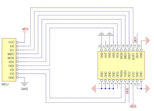
Connection instructions to the emulator
FAQ
Communication range is too short
- When there is a linear communication obstacle, the communication distance will be attenuated accordingly;
- Temperature, humidity and co frequency interference will increase the packet loss rate;
- The ground absorbs and reflects radio waves, and the test effect near the ground is poor;
- Seawater has a strong ability to absorb radio waves, so the seaside test effect is poor.
- If there are metal objects near the antenna or placed in the metal shell, the signal attenuation will be very serious;
- Power register setting error, air speed setting too high (the higher the air speed, the closer the distance);
- The lower the voltage is, the smaller the power is;
- The matching degree between the antenna and the module is poor or the quality of the antenna itself is poor.
Module is easy to damage
- Please check the power supply to ensure that it is between the recommended supply voltage. If it exceeds the maximum value, the module will be permanently damaged.
- Please check the stability of the power supply. The voltage should not fluctuate greatly and frequently.
- Please ensure that the installation process of anti-static operation, high-frequency device electrostatic sensitivity.
- Please ensure that the humidity should not be too high during installation and use, and some components are humidity sensitive devices.
- If there is no special requirement, it is not recommended to use it at too high or too low temperature.
BER(Bit Error Rate) is high
- If there is interference of the same frequency signal nearby, stay away from the interference source or modify the frequency and channel to avoid interference;
- The clock waveform on SPI is not standard, check whether there is interference on SPI line, and SPI bus line should not be too long;
- If the power supply is not ideal, it may cause garbled code, so it is necessary to ensure the reliability of the power supply;
- If the quality of extension line and feeder is poor or too long, the bit error rate will be high;
Production guidance
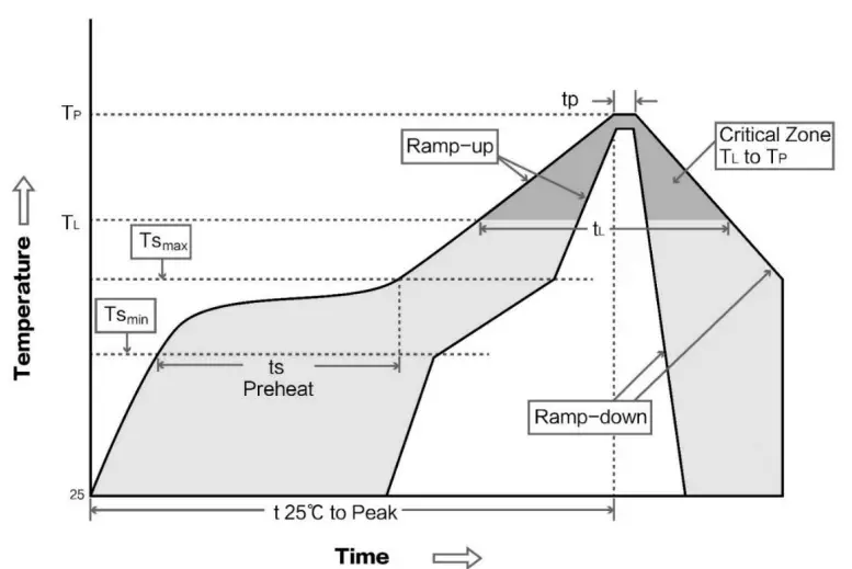
Reflow soldering temperature
| Profile Feature | Curve characteristics | Sn-Pb Assembly | Pb-Free Assembly |
| Solder Paste | Solder paste | Sn63/Pb37 | Sn96.5/Ag3/Cu0.5 |
| Preheat Temperature min (Tsmin) | Minimum preheating temperature | 100 degrees | 150 degrees. |
| Preheat temperature max (Tsmax) | Maximum preheating temperature | 150 degrees. | 200 degrees |
| Preheat Time (Tsmin to Tsmax)(ts) | Preheating time | 60-120 sec | 60-120 sec |
| Average ramp-up rate(Tsmax to Tp) | Average rising rate | 3℃/second max | 3℃/second max |
| Liquidous Temperature (TL) | Liquid temperature | 183 degrees. | 217 degrees. |
| Time(tL)Maintained Above(TL) | Time above liquidus | 60-90 sec | 30-90 sec |
| Peak temperature(Tp) | Peak temperature | 220-235 degrees | 230 to 250 degrees. |
| Aveage ramp-down rate(Tp to Tsmax) | Average descent rate | 6℃/second max | 6℃/second max |
| Time 25℃ to peak temperature | Time from 25 ℃ to peak temperature | 6 minutes max | 8 minutes max |
Reflow soldering curve
E220 series
| Model No. | IC | Frequency Hz | Tx power dBm | Distance km | Package | Size mm | Antenna |
| E220-900M22S | LLCC68 | 868M/915M | 22 | 5.5 | SMD | 14*20 | SPI |
| E22-400M22S | SX1268 | 433M/470M | 22 | 5.0 | SMD | 14*20 | SPI |
9 Antenna recommendation
Recommendation
The antenna is an important role in the communication process. A good antenna can largely improve the communication system. Therefore, we recommend some antennas for wireless modules with excellent performance and reasonable price.
| Model No. | Type | Frequeny Hz | Interface | Gain dBi | Hright | Cable | Function feature |
| Rubber rod antenna | 868M | SMA-J | 2.0 | 52 | – | Ultra short direct omnidirectional antenna | |
| Rubber rod antenna | 868M | SMA-J | 3.0 | 210 | – | Bendable rubber rod, omnidirectional antenna | |
| Sucker antenna | 868M | SMA-J | 3.5 | 290 | 100 | Small suction cup antenna, high cost performance | |
| Rubber rod antenna | 915M | SMA-J | 2.0 | 52 | – | Ultra short direct omnidirectional antenna | |
| Rubber rod antenna | 915M | SMA-J | 2.5 | 110 | – | Bendable rubber rod, omnidirectional antenna | |
| Rubber rod antenna | 915M | SMA-J | 3.0 | 210 | – | Bendable rubber rod, omnidirectional antenna | |
| Sucker antenna | 915M | SMA-J | 3.5 | 290 | 100 | Small suction cup antenna, high cost performance |
Revision history
| Version | Date | Description | Issued by |
| 1.0 | 2021-01-04 | Initial version | Linson |
About us
- Technical support:
[email protected] Documents and RF Setting download link: www.ebyte.com
Thank you for using Ebyte products! Please contact us with any questions or suggestions: [email protected] - Phone: +86 028-61399028
- Web: www.ebyte.com
- Address: B5 Mould Park, 199# Xiqu Ave, High-tech District, Sichuan, China


