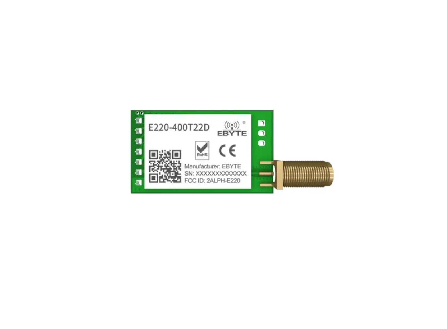
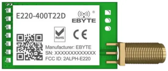
EBYTE E220-400T22D 433/470MHz 22dBm LoRa Wireless Module

Overview
Introduction
E220-400T22D adopts a new generation of LoRa spread spectrum technology and a wireless serial port module (UART) designed based on the LLCC68 chip scheme. It has a variety of transmission methods, works in the (410.125493.125MHz) frequency band (default 433.125MHz), TTL level output, compatible with 3.3V and 5V IO port voltage.
E220-400T22D adopts a new generation of LoRa spread spectrum technology, supports air wake-up, carrier sense, communication key and other functions, supports sub-package length setting, and Ebyte provides customized development services.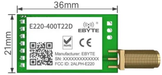
Features
- The new LoRa spread spectrum modulation technology developed based on LLCC68, it brings a longer communication distance and stronger anti-interference ability;
- Support users to set the communication key by themselves, and it cannot be read, which greatly improves the confidentiality of user data;
- Support LBT function, monitor the channel environment noise before sending, which greatly improves the communication success rate of the module in harsh environments;
- Support RSSI signal strength indicator function for evaluating signal quality, improving communication network, and ranging;
- Support air wakeup, that is ultra-low power consumption, suitable for battery-powered applications;
- Support point to point transmission, broadcast transmission, channel sense;
- Support deep sleep, the power consumption of the whole machine is about 5uA in this mode;
- The module has built-in PA+LNA, and the communication distance can reach 5km under ideal conditions;
- The parameters are saved after power-off, and the module will work according to the set parameters after power-on;
- Efficient watchdog design, once an exception occurs, the module will automatically restart and continue to work according to the previous parameter settings;
- Support the bit rate of 2.4k~62.5kbps;
- Support 3.0~5.5V power supply, power supply greater than 5V can guarantee the best performance;
- Industrial standard design, supporting long-term use at -40~+85℃;
- SMA antenna interface.
Application
- Home security alarm and remote keyless entry;
- Smart home and industrial sensors;
- Wireless alarm security system;
- Building automation solutions;
- Wireless industrial-grade remote control;
- Advanced Meter Reading Architecture (AMI);
Specification and Parameter
Limit Parameter
Table 2-1 Limit parameter table
| Main Parameter | Performance | Remark | |
| Min. | Min. | ||
| Power Supply(V) | 0 | 5.5 | Exceeding the maximum value may burn the module permanently |
| Blocking Power(dBm) | – | 10 | – |
| Operating Temperature(℃) | -40 | +85 | Industrial grade |
Operating Parameter
Table 2-2 Working parameter table
| Main Parameter | Performance | Remark | |||
| Min. | Typ. | Max. | |||
| Operating voltage(V) | 3.0 | 5 | 5.5 | ≥5.0 V ensures output power | |
| Communication level(V) | – | 3.3 | – | For 5V TTL, it may be burning down | |
| Operating temperature(℃) | -40 | – | +85 | Industrial design | |
| Operating frequency(MHz) | 410.125 | – | 493.125 | Support ISM band | |
| Power consumption | TX current(mA) | – | 110 | – | Instant power consumption @30dBm |
| RX current (mA) | – | 16.8 | – | 5V Voltage | |
| Sleep current(μA) | – | 5 | – | Sleep mode | |
| Max Tx power(dBm) | 21.5 | 22.0 | 22.5 | – | |
| Receiving sensitivity(dBm) | -146 | -147 | -148 | Air data rate 2.4kbps | |
| Air data rate(bps) | 2.4k | 2.4k | 62.5k | To control via user’s program | |
| Distance for reference | 5km | Test condition:clear and open area, antenna gain: 5dBi,antenna height: 2.5m,air data rate: 2.4kbps | |||
| TX length | 200 Byte | Can be configured via command as 32/64/128/200 bytes per packet to transmit | |||
| Buffer | 400 Byte | – | |||
| Modulation | LoRa | New generation LoRa modulation technology | |||
| Communication interface | UART Serial Port | TTL Level | |||
| Package | DIP | – | |||
| Size | 21*36mm | – | |||
| Antenna | SMA-K | 50 ohm impedance | |||
Size and Pin Definition
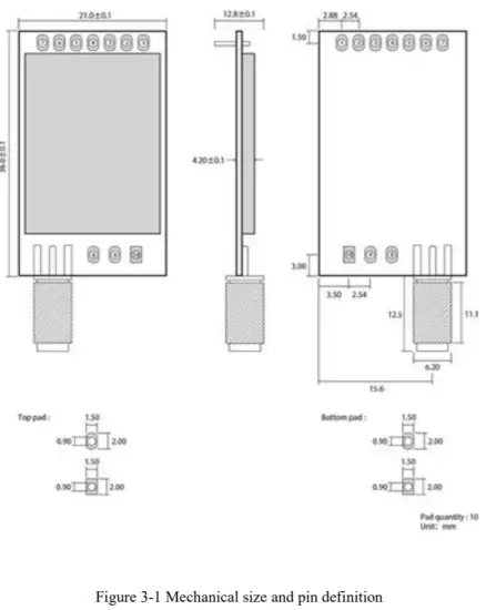
| No. | Name | Direction | Function |
| 1 | M0 | Input(weak pull-up) | Work with M1 to decide 4 working modes of module (not suspended, if not used, could be grounded). |
| 2 | M1 | Input(weak pull-up) | Work with M0 to decide 4 working modes of module (not suspended, if not used, could be grounded). |
| 3 | RXD | Input | TTL UART inputs, connects to external TXD output pin. |
| 4 | TXD | Output | TTL UART outputs, connects to external RXD input pin. |
| 5 | AUX | Output | Used to indicate the working status of the module; the user wakes up the external MCU, and outputs low level during power-on self-check initialization; (can be left floating) |
| 6 | VCC | Input | Voltage range: 3.0~5.5V DC |
| 7 | GND | Input | Ground |
| 8 | Fixed hole | – | Fixed hole |
| 9 | Fixed hole | – | Fixed hole |
| 10 | Fixed hole | – | Fixed hole |
Recommended Connection Diagram
Table 4-1 Description
| No. | Brief description of the connection between the module and the MCU (the above figure uses the STM8L MCU as an example) |
| 1 | The wireless serial port module is TTL level, please connect with TTL level MCU. |
| 2 | For some 5V MCU, it may be necessary to add 4-10K pull-up resistors to the TXD and AUX pins of the module. |
Function Description
Fixed Transmission
Broadcasting Transmission
Broadcasting Address
- Example: Set the address of module A to 0xFFFF and the channel to 0x04.
- When module A is used as a transmitter (same mode, transparent transmission mode), all receiving modules under the 0x04 channel can receive data to achieve the purpose of broadcasting.
Monitor Address
- For example: Set the address of module A as 0xFFFF or 0x0000, and the channel as 0x04;
- When module A is the receiver, it can receive the data sent from all modules under channel 0x04, the purpose of monitor is realized.
Reset
After the module is powered on, AUX will immediately output low level, perform hardware self-check, and set the working mode according to user parameters; During this process, AUX keeps low level, and AUX outputs high level after completion, and starts to work normally according to the working mode formed by M1 and M0; Therefore, the user needs to wait for the rising edge of AUX as the starting point for the module to work normally.
AUX Description
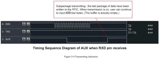
- AUX Pin can be used as indication for wireless send & receive buffer and self-check.
- It can indicate whether there are data that are not sent yet via wireless way, or whether all wireless data has been sent through UART, or whether the module is still in the process of self-check initialization.
Indication of UART Output
- To wake up external MCU

Indication of Wireless Transmitting
- Buffer empty: the data in the internal 400-byte buffer is written to the wireless chip (automatic sub-packaging); When AUX=1, the user continuously initiates data less than 400 bytes without overflow; When AUX=0, the buffer is not empty: the data in the internal 400-byte buffer has not been written to the wireless chip and the transmission is turned on. At this time, the module may be waiting for the end of the user data to time out, or the wireless sub-packet transmission is in progress;
[Note]: When AUX=1, it does not mean that all serial port data of the module has been transmitted wirelessly, and the last packet of data may be being transmitted.
Configuration Procedure of Module
- Only happened when power-on resetting or exiting sleep mode
Notes for AUX
Table 5-1 Notes for AUX
| No. | Description |
| 1 | For function 1 & function 2 mentioned above, the priority should be given to the one with low level output, which means if it meets each of any low level output condition, AUX outputs low level, if none of the low level condition is met, AUX outputs high level. |
| 2 | When AUX outputs low level, it means the module is busy & cannot conduct operating mode checking. Within 1ms since AUX outputs high level, the mode switch will be completed. |
| 3 | After switching to new operating mode, it will not work in the new mode immediately until AUX rising edge lasts for 2ms. If AUX stays on the high level, the operating mode switch can be affected immediately. |
| 4 | When the user switches to other operating modes from mode 3 (sleep mode) or it’s still in reset process, the module will reset user parameters, during which AUX outputs low level. |
| 5 | Due to the characteristics of the LoRa modulation method, the information transmission delay is much longer than FSK. It is recommended that customers do not transmit large amounts of data at low airspeeds to avoid communication abnormalities caused by data accumulation and data loss. |
Operating Mode
There are four operating modes, which are set by M1 and M0, the details are as follows:
| Mode(0-3) | M1 | M0 | Description | Remark |
| 0 Transmission Mode | 0 | 0 | UART and wireless channel are open, transparent transmission is on | |
| 1 WOR Transmitting Mode | 0 | 1 | WOR Transmitter | |
| 2 WOR Receiving Mode | 1 | 0 | WOR Receiver | Supports wake up over air |
| 3 Deep Sleep Mode | 1 | 1 | Module goes to sleep (automatically wake up when configuring parameters) | Supports configuration |
Mode Switching
Table 6-1 Mode Switching
| No. | Remark |
| 1 |
|
| 2 |
|
| 3 |
|
| 4 |
|
| 5 |
|
Normal mode(Mode 0)
Table 6-2 Normal mode
| Type | When M0 = 0, M1 = 0, the module works in mode 0 |
| Transmitting | Users can input data through the serial port and the module will start wireless transmission. |
| Receiving | The module wireless receiving function is turned on, and after receiving the wireless data, it will be output through the serial port TXD pin. |
WOR sending mode (Mode 1)
Table 6-3 WOR sending mode
| Type | When M0 = 1, M1 = 1, the module works in mode 1 |
| Transmitting | When defined as a transmitting party, a preamble is automatically added before transmitting. |
| Receiving | It can receive data normally, the receiving function is the same as mode 0. |
WOR receiving mode (Mode 2)
Table 6-4 WOR receiving mode
| Type | When M0 = 0, M1 = 1, the module works in mode 2 |
| Transmitting | Wireless transmission off |
| Receiving | Can only receive data in WOR transmission mode (mode 1) |
Deep Sleep (Configuration) Mode (Mode 3)
Table 6-5 Sleep mode
| Type | When M0 = 1, M1 = 1, the module works in mode 3 |
| Transmitting | Unable to transmit wireless data |
| Receiving | Unable to receive wireless data |
| Note | When from the sleep mode to other modes, the module will reconfigure the parameters. During the configuration process, AUX will remain low; After configuration, it outputs high level, we suggest that user test rising edge T_BUSY. |
Register Read and Write Control
Command Format
In configuration mode (mode 3: M1=1, M0=1), the supported command list is as follows (when setting, only 9600, 8N1 format is supported):
Table 7-1 Command format
| No | Command Format | Description |
| 1 | Write Register | Command: C0+starting address+length+parameters Response: C1+starting address+length+parameters Example 1: Channel is 0x09 command starting address length parameter Send: C0 04 01 09 Return:C1 04 01 09 Example 2:Configure module address (0x1234), serial port (9600 8N1), air speed (2.4K) Send: C0 00 03 12 34 62 Return:C1 00 03 12 34 62 |
| 2 | Read Register | Command: C1+starting address+parameters Response: C1+starting address+length+parameters Example:Read channel command starting address length parameter Send: C1 04 01 Return: C1 04 01 09 Example 2: Read module address, serial port, and airspeed at the same time Send: C1 00 03 Return:C1 00 03 12 34 62 |
| 3 | Write Temporary Register | Command: C2+starting address+parameters Response: C1+starting address+length+parameters Example 1: Channel is 0x09 command starting address length parameter Send: C2 04 01 09 Return: C1 04 01 09 Example 2: Configure module address (0x1234), network address (0x00), serial port (9600 8N1) and air data rate (2.4K) Send:C2 00 03 12 34 62 Return:C1 00 03 12 34 62 |
| 4 | Wrong Format | Wrong format respond: FF FF FF |
Register Description
Table 7-2 Register description
| Address | Read or Write | Name | Description | Remark | ||||||||||
| 00H | Read/ Write | ADDH | ADDH(default 0) | High byte and low byte of module address; Note: When the module address is equal to FFFF, it can be used as the broadcast and monitor address, that is: the module will not perform address filtering at this time | ||||||||||
| 01H | Read/ Write | ADDL | ADDL(default 0) | |||||||||||
| 02H | Read/ Write | REG0 | 7 | 6 | 5 | UART Serial Port Rate(bps) | For the two modules that communicate with each other, the serial port baud rate can be different, and the verification method can also be different;
When continuously transmitting large data packets, users need to consider the data congestion caused by the same baud rate, and may even be lost;
It is generally recommended that the baud rate of the two communication parties be the same. | |||||||
| 0 | 0 | 0 | UART Rate is 1200 | |||||||||||
| 0 | 0 | 1 | UART Rate is 2400 | |||||||||||
| 0 | 1 | 0 | UART Rate is 4800 | |||||||||||
| 0 | 1 | 1 | UART Rate is 9600(default) | |||||||||||
| 1 | 0 | 0 | UART Rate is 19200 | |||||||||||
| 1 | 0 | 1 | UART Rate is 38400 | |||||||||||
| 1 | 1 | 0 | UART Rate is 57600 | |||||||||||
| 1 | 1 | 1 | UART Rate is 115200 | |||||||||||
| 4 | 3 | Serial Parity Bit |
The serial port mode of the communication parties can be different; | |||||||||||
| 0 | 0 | 8N1(default) | ||||||||||||
| 0 | 1 | 8O1 | ||||||||||||
| 1 | 0 | 8E1 | ||||||||||||
| 1 | 1 | 8N1(equal to 00) | ||||||||||||
| 2 | 1 | 0 | Air Data Rate(bps) | The air rate of both parties must be the same; | ||||||||||
| 0 | 0 | 0 | Air Data Rate 2.4k | The higher the air rate, the smaller the delay and the shorter the transmission distance. | ||||||||||
| 0 | 0 | 1 | Air Data Rate 2.4k | |||||||||||
| 0 | 1 | 0 | Air Data Rate 2.4k(default) | |||||||||||
| 0 | 1 | 1 | Air Data Rate 4.8k | |||||||||||
| 1 | 0 | 0 | Air Data Rate 9.6k | |||||||||||
| 1 | 0 | 1 | Air Data Rate 19.2k | |||||||||||
| 1 | 1 | 0 | Air Data Rate 38.4k | |||||||||||
| 1 | 1 | 1 | Air Data Rate 62.5k | |||||||||||
| 03H | Read/ Write | REG1 | 7 | 6 | Sub-Packet Setting | The data sent by the user is less than the sub-packet length, and the serial port output of the receiving end appears as an uninterrupted continuous output; | ||||||||
| 0 | 0 | 200 bytes(default) | ||||||||||||
| 0 | 1 | 128 bytes | ||||||||||||
| 1 | 0 | 64 bytes | ||||||||||||
| 1 | 1 | 32 bytes | ||||||||||||
| 5 | RSSI Ambient noise enable | After enabling, you can send commands C0 C1 C2 C3 in transmission mode or WOR sending mode to read registers; Register 0x00: Current environmental noise RSSI; Register 0X01: RSSI when receiving data last time (The current channel noise is: dBm = – ( 256 – RSSI)); Instruction format: C0 C1 C2 C3+start address+read length; | ||||||||||||
| 0 | Disable(Default) | |||||||||||||
| 1 | Enable | |||||||||||||
| 4 | 3 | 2 | Reserve | |||||||||||
| 1 | 0 | Transmitting Power | The relationship between power and current is non-linear, and the power supply has the highest efficiency at maximum power; The current will not decrease in the same proportion as the power decreases. | |||||||||||
| 0 | 0 | 22dBm(default) | ||||||||||||
| 0 | 1 | 17dBm | ||||||||||||
| 1 | 0 | 13dBm | ||||||||||||
| 1 | 1 | 10dBm | ||||||||||||
| 04H | Read/ Write | REG2 | Channel Control(CH) 0-83 represents a total of 84 channels | Actual frequency = 410.125 + CH *1M | ||||||||||
| 05H | Read/ Write | REG3 | 7 | Enable RSSI Byte | After being enabled, the module receives wireless data and outputs it through the serial port TXD, followed by an RSSI strength byte. | |||||||||
| 0 | Disable(Default) | |||||||||||||
| 1 | Enable | |||||||||||||
| 6 | Transmission Method | During fixed transmission, the module will recognize the first three bytes of serial data as: address high + address low + channel, and use it as a wireless transmission target. | ||||||||||||
| 0 | Transparent transmission mode(default) | |||||||||||||
| 1 | Fixed transmission mode | |||||||||||||
| 5 | Reserve | |||||||||||||
| 4 | LBT Enable | After enabling, monitoring will be conducted before wireless data transmission, which can avoid interference to a certain extent, but may cause data delaThe maximum stay time of LBT is 2 seconds, and | ||||||||||||
| 0 | Disable(default) | |||||||||||||
| 1 | Enable | |||||||||||||
| it will be issued forcibly when it reaches 2 seconds. | ||||||||||||||
| 3 | Reserve | |||||||||||||
| 2 | 1 | 0 | WOR Cycle | Only valid for mode 1; | ||||||||||
Factory Default Parameter
Table 7-3 Default parameters
Model | Factory default parameter:c0 00 00 62 00 17 | ||||||
Module No. | Frequency | Module No. | Frequency | Module No. | Frequency | Module No. | Frequency |
| E220-400T22D | 433.125MHz | 0x0000 | 0x17 | 2.4kbps | 9600 | 8N1 | 22dbm |
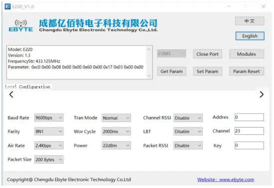
Configuration Instruction on Computer
- The following figure shows the display interface of the E220-400T22D configuration host computer. The user can switch to the command mode through M0 and M1, and quickly configure and read the parameters on the host computer.

- In the configuration of the host computer, the module address, frequency channel, network ID, and key are all displayed in decimal mode; the value range of each parameter:
Network address:0~65535
Frequency channel:0~83
Key:0~65535
Hardware Design
- It is recommended to use a DC stabilized power supply to supply power to the module. The power ripple coefficient should be as small as possible, and the module must be reliably grounded;
- Please pay attention to the correct connection of the positive and negative poles of the power supply. Reverse connection may cause permanent damage to the module;
- Please check the power supply to ensure that it is within the recommended power supply voltage. If it exceeds the maximum value, it will cause permanent damage to the module;
- Please check the stability of the power supply, the voltage should not fluctuate greatly and frequently;
- When designing the power supply circuit for the module, it is often recommended to reserve more than 30% of the margin, and the whole machine is conducive to long-term stable operation;
- The module should be as far away as possible from power supply, transformer, high frequency wiring and other parts with large electromagnetic interference;
- High-frequency digital traces, high-frequency analog traces, and power traces must avoid under the module. If they really need to pass under the module, assuming that the module is soldered to the Top Layer, lay copper on the Top Layer of the contact part of the module (all copper and Good grounding), must be close to the digital part of the module and routed in the Bottom Layer;
- Assuming that the module is soldered or placed on the Top Layer, it is also wrong to randomly route the wires on the Bottom Layer or other layers, which will affect the stray and receiving sensitivity of the module to varying degrees;
- Assuming that there are devices with large electromagnetic interference around the module, it will greatly affect the performance of the module. According to the intensity of the interference, it is recommended to stay away from the module. If the situation permits, proper isolation and shielding can be done;
- Assuming that there are traces with large electromagnetic interference around the module (high-frequency digital, high-frequency analog, power wiring), it will also greatly affect the performance of the module. According to the intensity of the interference, it is recommended to stay away from the module. Isolation and shielding;
- Try to stay away from part of the physical layer that is also 2.4GHz TTL protocol, such as: USB3.0;
- The antenna installation structure has a great influence on the performance of the module. Make sure that the antenna is exposed and it is best to be vertically upward;
- When the module is installed inside the case, a high-quality antenna extension cable can be used to extend the antenna to the outside of the case;
- The antenna must not be installed inside the metal shell, which will greatly reduce the transmission distance.
FAQ
Communication range is too short
- When there is a straight-line communication obstacle, the communication distance will be attenuated accordingly;
- Temperature, humidity, and co-frequency interference will increase the communication packet loss rate;
- The ground absorbs and reflects radio waves, and the test results near the ground are poor;
- Sea water has a strong ability to absorb radio waves, so the seaside test results are poor;
- If there is a metal object near the antenna or placed in a metal shell, the signal attenuation will be very serious;
- The power register setting is wrong, the air speed setting is too high (the higher the air speed, the closer the distance);
- The low voltage of the power supply at room temperature is lower than the recommended value, the lower the voltage, the lower the power output;
- The matching degree of the antenna and the module is poor or the quality of the antenna itself is problematic.
Module is easy to damage
- Please check the power supply to ensure that it is within the recommended power supply voltage. If it exceeds the maximum value, the module will be permanently damaged;
- Please check the stability of the power supply, and the voltage should not fluctuate greatly and frequently;
- Please ensure anti-static operation during installation and use, and high frequency components are electrostatically sensitive;
- Please ensure that the humidity during installation and use should not be too high, and some components are humidity sensitive devices;
- If there is no special requirement, it is not recommended to use it at too high or too low temperature.
BER (Bit Error Rate) is high
- There is co-frequency signal interference nearby, stay away from the interference source or modify the frequency and channel to avoid interference;
- Unsatisfactory power supply may also cause garbled codes. Ensure the reliability of the power supply;
- Poor or too long extension cables and feeders can also cause high bit error rates.
Soldering Operation Guidance
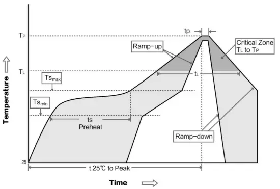
Reflow Soldering Temperature
Table 11-1 Register description
| Profile Feature | Sn-Pb Assembly | Pb-Free Assembly |
| Solder Paste | Sn63/Pb37 | Sn96.5/Ag3/Cu0.5 |
| Preheat Temperature min (Tsmin) | 100℃ | 150℃ |
| Preheat temperature max (Tsmax) | 150℃ | 200℃ |
| Preheat Time (Tsmin to Tsmax)(ts) | 60-120 sec | 60-120 sec |
| Average ramp-up rate(Tsmax to Tp) | 3℃/second max | 3℃/second max |
| Liquidous Temperature (TL) | 183℃ | 217℃ |
| Time(tL)Maintained Above(TL) | 60-90 sec | 30-90 sec |
| Peak temperature(Tp) | 220-235℃ | 230-250℃ |
| Aveage ramp-down rate(Tp to Tsmax) | 6℃/second max | 6℃/second max |
| Time 25℃ to peak temperature | 6 minutes max | 8 minutes max |
Reflow Soldering Curve
| Model No. | Chip Scheme | Frequency Hz | Tx power dBm | Distance km | Package | Size mm | Interface |
| E220-400T22S | LLCC68 | 433/470M | 22 | 5 | SMD | 16*26 | TTL |
| E220-400T30S | LLCC68 | 433/470M | 30 | 10 | SMD | 20*40.5 | TTL |
| E220-900T22S | LLCC68 | 868/915M | 22 | 5 | SMD | 16*26 | TTL |
| E220-900T30S | LLCC68 | 868/915M | 30 | 10 | SMD | 20*40.5 | TTL |
| E220-400T22D | LLCC68 | 433/470M | 22 | 5 | DIP | 21*36 | TTL |
| E220-400T30D | LLCC68 | 433/470M | 30 | 10 | DIP | 24*43 | TTL |
| E220-900T22D | LLCC68 | 868/915M | 22 | 5 | DIP | 21*36 | TTL |
| E220-900T30D | LLCC68 | 868/915M | 30 | 10 | DIP | 24*43 | TTL |
Antenna Recommendation
Antenna Recommendation
Antennas are an important role in the communication process, and often inferior antennas will have a great impact on the communication system. Therefore, our company recommends some antennas as supporting our company’s wireless modules with excellent performance and reasonable prices.
| Model No. | Type | Frequency Hz | Interface | Gain dBi | Height mm | Feeder cm | Features |
| TX433-JZ-5 | Rubber Antenna | 433M | SMA-J | 2.0 | 52 | – | Ultra-short straight, omnidirectional antenna |
| TX433-JZG-6 | Rubber Antenna | 433M | SMA-J | 2.5 | 62 | – | Sort straight, omnidirectional antenna |
| TX433-JW-5 | Rubber Antenna | 433M | SMA-J | 2.0 | 50 | – | Ultra-short straight, omnidirectional antenna |
| TX433-JWG-7 | Rubber Antenna | 433M | SMA-J | 2.5 | 75 | – | Bend rubber, omnidirectional antenna |
| TX433-JK-11 | Rubber Antenna | 433M | SMA-J | 2.5 | 110 | – | Bendable rubber, omnidirectional antenna |
| TX433-JK-20 | Rubber Antenna | 433M | SMA-J | 3.0 | 210 | – | Bendable rubber, omnidirectional antenna |
| TX433-XPL-100 | Suction Antenna | 433M | SMA-J | 3.5 | 185 | 100 | Small suction antenna, cost-effective |
| TX433-XP-200 | Suction Antenna | 433M | SMA-J | 4.0 | 190 | 200 | Middle suction antenna, high |
| TX433-XPH-300 | Suction Antenna | 433M | SMA-J | 6.0 | 965 | 300 | Big suction antenna, high gain |
| TX490-JZ-5 | Rubber Antenna | 470/490M | SMA-J | 2.0 | 50 | – | Ultra-short straight, omnidirectional antenna |
| TX490-XPL-100 | Suction Antenna | 470/490M | SMA-J | 3.5 | 120 | 100 | Small suction antenna, cost-effective |
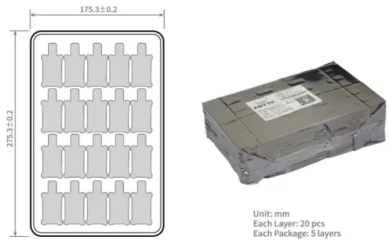
Package for Bulk Order
Revision History
Version | Date | Description | Issued by |
| 1.0 | 2020-8-28 | Original version | Linson |
About us
Technical support: [email protected]
Documents and RF Setting download link: www.ebyte.com
Thank you for using Ebyte products! Please contact us with any questions or suggestions: [email protected]
Official hotline:028-61399028
Web: www.ebyte.com
Address: , Building B5, Mould Industrial Park, 199# Xiqu Ave, High-tech Zone, Chengdu, 611731, Sichuan, China