EBYTE E30-400M30S 446 SI4463 400MHz 1W SPI Wireless Module
Disclaimer
EBYTE reserves all rights to this document and the information contained herein. Products, names, logos and designs described herein may in whole or in part be subject to intellectual property rights. Reproduction, use, modification or disclosure to third parties of this document or any part thereof without the express permission of EBYTE is strictly prohibited.
The information contained herein is provided “as is” and EBYTE assumes no liability for the use of the information. No warranty, either express or implied, is given, including but not limited, with respect to the accuracy, correctness, reliability and fitness for a particular purpose of the information. This document may be revised by EBYTE at any time. For most recent documents, visit www.ebyte.com
OVERVIEW
Brief Introduction
E30-400M30S(4463) is a hardware module (SPI) based on the SI4463 RF chip imported from Silicon Labs. It is a half-duplex, SMD integrated transceiver with transparent transmission available. With working frequency band 425 ~525MHz, transmitting power 1w, it is suitable for a variety of environments. The original imported SI4463 RF chip from Silicon Labs(USA) features high receiving sensitivity and strong anti-interference, supporting the development of low power consumption as well. It has been widely used in various industries and has the characteristics of stable performance, long transmission distance, and strong ability of penetration and diffraction, etc.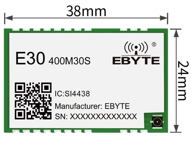
Features
- The measured communication distance is up to 5.6km;
- Maximum transmission power: 1W;
- 425-525MHz ultra-wide frequency band;
- Air date rate:1k~25kbps;
- With 3.3~5.5V power supply, over 5 V guarantees the best performance;
- Industrial grade standard design,support -40 ~ 85 °C for working over a long time;
Application
- Home security alarm and remote keyless entry;
- Smart home and industrial sensors, etc.;
- Wireless alarm security system;
- Building automation solutions;
- Wireless industrial-grade remote control;
- Intelligent agriculture and oilfield solutions;
- Health care products;
- Advanced Meter Reading Architecture(AMI);
- Automotive industry applications.
Specification and Parameter
Limit Parameter
| Main parameter | Performance | Remark | |
| Min | Max | ||
| Power supply(V) | 3.3 | 5.5 | Voltage over 5.5V will cause permanent damage to module |
| Blocking power(dBm) | – | 10 | Chances of burn is slim when modules are used in short distance |
| Operating temperature(℃) | -40 | +85 | Industrial grade |
Operating Parameter
| Main parameter | Performance | Remark | |||
| Min | Typical | Max | |||
| Operating voltage(V) | 3.3 | 5.0 | 5.5 | 5 V ensures output power | |
| Communication level(V) | – | 3.3 | – | For 5V TTL, it may be at risk of burning down | |
| Operating temperature(℃) | -40 | – | +85 | Industrial grade | |
| Operating frequency(MHz) | 425 | – | 525 | – | |
| Power Consump – tion | TX current(mA) | 550 | 650 | 700 | Instant power consumption |
| RX current(mA) | – | 22 | – | – | |
| Sleep current (μA) | – | 2 | – | – | |
| Max TX power(dBm) | 29 | 30 | 30.5 | – | |
| Receiving sensitivity(dBm) | -120 | -121 | -122 | Air data rate is1kbps | |
| Main parameter | Description | Remark |
| Reference distance | 5.6Km | Test condition:clear and open area, antenna gain: 5dBi, antenna height: 2.5m,air data rate: 1kbps |
| Modulation | GFSK | – |
| Communication Interface | SPI | Max. rate 10Mbps |
| Package | SMD | – |
| Interface method | Stamp Hole | – |
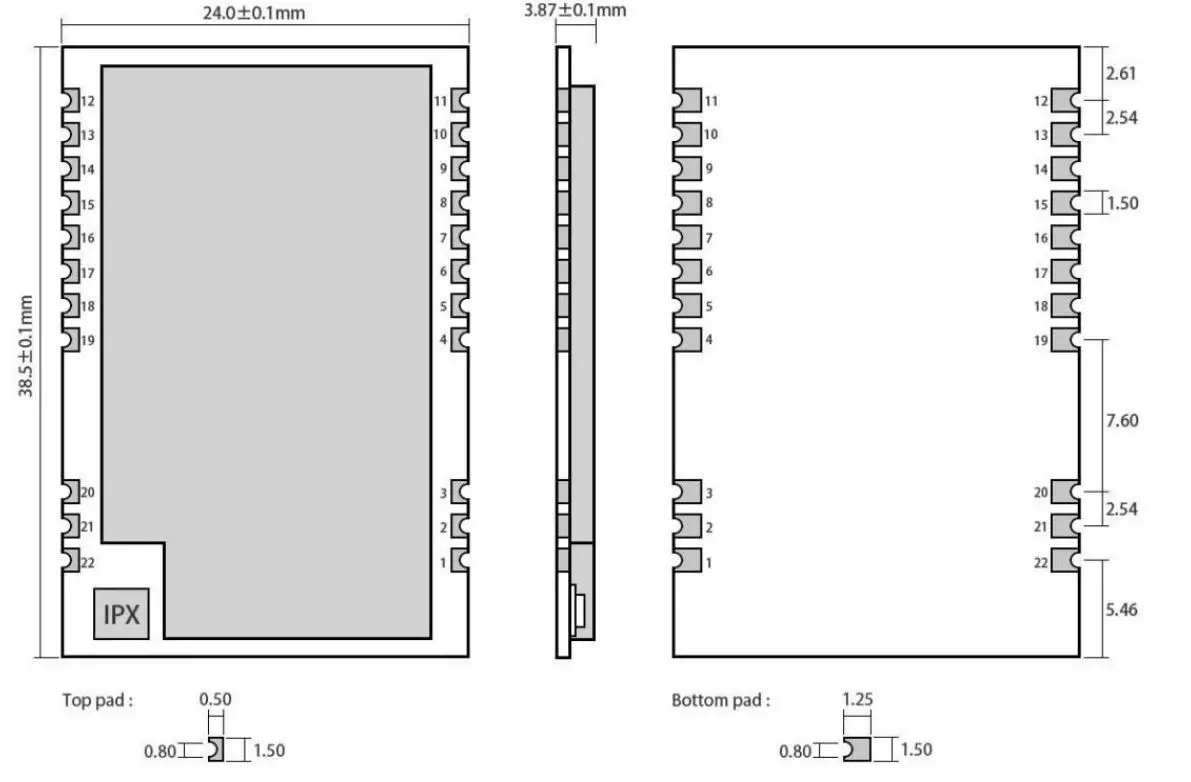
| Size | 38.5*24mm | – |
| Antenna | IPEX/STAMP | 50 ohm impedance |
Size and Pin definition
| Pin No. | Item | Direction | Description |
| 1 | GND | Ground wire, connected to the power reference ground | |
| 2 | GND | Ground wire, connected to the power reference ground | |
| 3 | GND | Ground wire, connected to the power reference ground | |
| 4 | GND | Ground wire, connected to the power reference ground | |
| 5 | GND | Ground wire, connected to the power reference ground | |
| 6 | IO_2 | Output | Configurable universal GPIO port (see SI4463manual for details) |
| 7 | IO_3 | Output | Configurable universal GPIO port (see SI4463manual for details) |
| 8 | IO_0 | Output | Configurable universal GPIO port (see SI4463manual for details) |
| 9 | VCC | Power supply, 3.3~5.5V, 5V is recommended (It is also recommended to add external ceramic filter capacitor) | |
| 10 | VCC | Power supply, 3.3~5.5V, 5V is recommended (It is also recommended to add external ceramic filter capacitor) | |
| 11 | GND | Ground wire, connected to the power reference ground | |
| 12 | GND | Ground wire, connected to the power reference ground | |
| 13 | IO_1 | Output | Configurable universal GPIO port (see SI4463manual for details) |
| 14 | IRQ | Output | SPI interrupt request |
| 15 | SDN | Shutdown Input Pin. It is low level when working (See SI4463 manual for more details) |
Chengdu Ebyte Electronic Technology Co.,Ltd Manual
| 16 | MISO | Output | SPI master output slave input |
| 17 | MOSI | Input | SPI master input slave output |
| 18 | SCK | Input | Serial Clock Input |
| 19 | nSEL | Input | SPI Chip select for starting SPI communication |
| 20 | GND | Ground wire, connected to the power reference ground | |
| 21 | ANT | Input/Output | Antena |
| 22 | GND | Ground wire, connected to the power reference ground |
Recommended circuit diagram
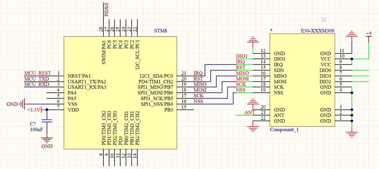
Hardware design
- It is recommended to use a DC stabilized power The power supply ripple factor is as small as possible and the module needs to be reliably grounded;
- Please pay attention to the correct connection of the positive and negative poles of the power supply, reverse connection may cause permanent damage to the module;
- Please check the power supply to ensure that between the recommended supply voltage, if exceeding the maximum, the module will be permanently damaged;
- Please check the stability of the power Voltage can not fluctuate greatly and frequently;
- When designing the power supply circuit for the module, it is often recommended to reserve more than 30% of the margin, so the whole machine is beneficial for long-term stable operation;
- The module should be as far away as possible from the power supply, transformers, high-frequency wiring and other parts with large electromagnetic interference;
- Bottom Layer High-frequency digital routing, high-frequency analog routing, and power routing must be avoided under the module. If it is necessary to pass through the module, assume that the module is soldered to the Top Layer, and the copper is spread on the Top Layer of the module contact part(well grounded), it must be close to the digital part of the module and routed in the Bottom Layer;
- Assuming the module is soldered or placed over the Top Layer, it is wrong to randomly route over the Bottom Layer or other layers, which will affect the module’s spurs and receiving sensitivity to varying degrees;
- It is assumed that there are devices with large electromagnetic interference around the module that will greatly affect the performance. It is recommended to keep them away from the module according to the strength of the interference. If necessary, appropriate isolation and shielding can be done;
- Assume that there are traces with large electromagnetic interference (high-frequency digital, high-frequency analog, power traces) around the module that will greatly affect the performance of the module. It is recommended to stay away from the module according to the strength of the interference.If necessary, appropriate isolation and shielding can be done;
- If the communication line uses a 5V level, a 1k-5.1k resistor must be connected in series (not recommended, there is still a risk of damage);
- Try to stay away from some physical layers such as TTL protocol at 400MHz;
- The mounting structure of antenna has a great influence on the performance of the module. It is necessary to ensure that the antenna is exposed, preferably vertically upward.
- When the module is mounted inside the case, use a good antenna extension cable to extend the antenna to the outside; When the antenna is installed inside a metal case, it will cause the transmission distance to be greatly weakened.
FAQ
The communication range is too short
- The communication distance will be affected when obstacle exists;
- Data lose rate will be affected by temperature, humidity and co-channel interference;
- The ground will absorb and reflect wireless radio wave, so the performance will be poor when testing near ground;
- Sea water has great ability in absorbing wireless radio wave, so performance will be poor when testing near the sea;
- The signal will be seriously affected when the antenna is near metal object or put in a metal case;
- Power register was set incorrectly or air data rate is set as too high (the higher the air data rate, the shorter the distance);
- The power supply low voltage under room temperature is lower than our recommendation, the lower the voltage, the lower the transmitting power;
- Due to antenna quality or poor matching between antenna and module.
Module is easy to damage
- Please check the power supply, ensure it works in correct voltage;
- Please check the stability of power source, the voltage cannot fluctuate too much;
- Please make sure anti-static operation when installing and using, high frequency devices have electrostatic susceptibility;
- Please ensure the humidity is within limited range, some parts are sensitive to humidity;
- Please avoid using modules under too high or too low temperature.
BER(Bit Error Rate) is high
- There are co-channel signal interference nearby, please be away from interference sources or modify frequency and channel to avoid interference;
- Poor power supply may cause messy code. Make sure that the power supply is reliable;
- The extension line and feeder quality are poor or too long, so the bit error rate is high.
Production guidance
This product is a SMD module. When soldering the module, the soldering personnel must work in accordance with the anti-static operation specification;
This product is an electrostatic sensitive product. If the module is not welded according to the specification, the module may be permanently damaged.
E30 series
| Model No. | IC | Frequency Hz | Tx power dBm | Distance km | Air data rate bps | Package | Size mm | Antenna |
| E30-170T20D | SI4463 | 170M | 20 | 2.0 | 1k~25k | DIP | 21 * 36 | SMA-K |
| E30-170T27D | SI4463 | 170M | 27 | 5.0 | 1k~25k | DIP | 24 * 43 | SMA-K |
| E30-433T20S3 | SI4438 | 433M | 20 | 2.5 | 1k~25k | SMD | 16 * 26 | IPEX/STAMP |
| E30-433T20S | SI4438 | 433M | 20 | 2.5 | 1k~25k | SMD | 17 * 30 | IPEX/STAMP |
| E30-433T20D1B | SI4438 | 433M | 20 | 2.5 | 1k~25k | DIP | 21 * 36 | SMA-K |
| E30-490T20S | SI4438 | 490M | 20 | 2.5 | 1k~25k | SMD | 17 * 30 | IPEX/STAMP |
| E30-490T20D | SI4438 | 490M | 20 | 2.5 | 1k~25k | DIP | 21 * 36 | SMA-K |
| E30-780T20S | SI4463 | 780M | 20 | 2.5 | 1k~25k | SMD | 17 * 30 | IPEX/STAMP |
| E30-868T20D | SI4463 | 868M | 20 | 2.5 | 1k~25k | DIP | 21 * 36 | SMA-K |
| E30-868T20S | SI4463 | 868M | 20 | 2.5 | 1k~25k | SMD | 17 * 30 | IPEX/STAMP |
| E30-915T20D | SI4463 | 915M | 20 | 2.5 | 1k~25k | DIP | 21 * 36 | SMA-K |
| E30-915T20S | SI4463 | 915M | 20 | 2.5 | 1k~25k | SMD | 17 * 30 | IPEX/STAMP |
Antenna recommendation
The antenna plays an important role in the communication process. A good antenna can largely improve the communication system. Therefore, we recommend some antennas for wireless modules with excellent performance and reasonable price.
| Model No. | Type | Frequeny Hz | Interface | Gain dBi | Hight mm | Cable mm | Function feature |
| TX433-JZLW-15 | Rubber | 433M | IPEX 1 | 3.0 | 165 | 150 | Rubber antenna for cabinet, omnidirectional |
| TX433-FPC-5711 | FPC | 433M | IPEX 1 | 2.5 | 57 | 68 | Cost-effective |
| TX433-PCB-3207 | PCB | 433M | IPEX 1 | 2.0 | 32 | 90 | PCB antenna, |
| TX433-FPC-4516 | FPC | 433M | IPEX 1 | 2.0 | 45 | 120 | Cost-effective |
| TX433-FPC-3208 | FPC | 433M | IPEX 1 | 2.0 | 32 | 90 | Cost-effective |
| TX470-JZLW-15 | Rubber | 470MHz | IPEX 1 | 3.0 | 155 | 150 | Rubber antenna for cabinet, omnidirectional |
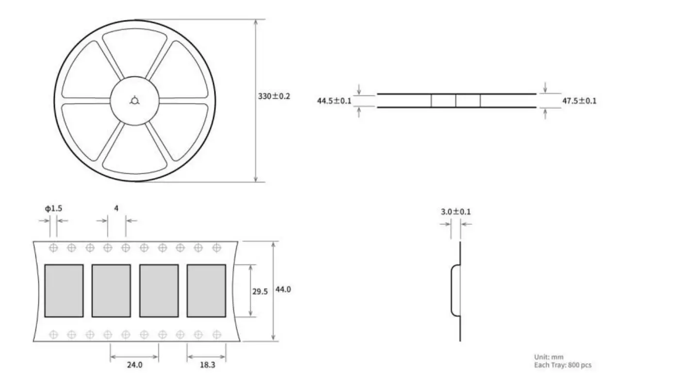
Package method for bulk order
About us
Technical support: [email protected]
Documents and RF Setting download link: www.ebyte.com
Thank you for using Ebyte products! Please contact us with any questions or suggestions: [email protected]
Phone: +86 028-61399028
Web: www.ebyte.com
Address: B5 Mould Park, 199# Xiqu Ave, High-tech District, Sichuan, China


