![]()
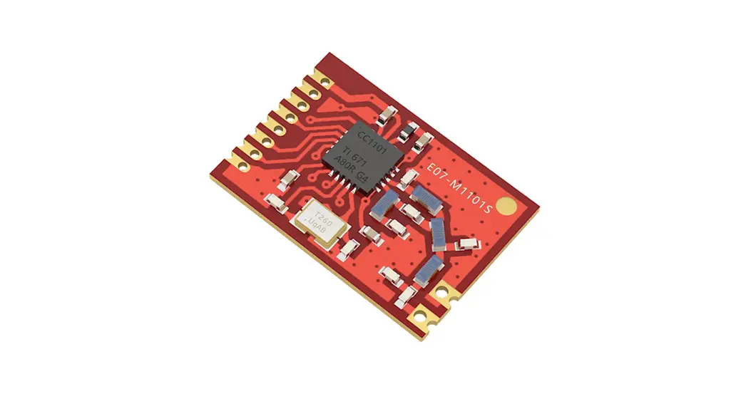
E07-900M10S
CC1101 904MHz~925MHz 10dBm SPI Wireless Module
Chengdu Ebyte Electronic Technology Co.,Ltd
Manual
Disclaimer
The information in this document, including the URL address for reference, is subject to change without notice. The document is provided “as is” without any guarantee of responsibility, including any guarantee for marketability, suitability for a specific purpose, or non-infringement, and any guarantee for any proposal, specification, or sample mentioned elsewhere. This document does not bear any responsibility, including the responsibility for infringement of any patent rights caused by the use of the information in this document. This document does not grant any license for the use of intellectual property rights in estoppel or other ways, whether express or implied.
The test data obtained in the article are all obtained by the Ebyte laboratory, and the actual results may vary slightly.
We hereby declared that all brand names, trademarks, and registered trademarks mentioned in this document are the property of their respective owners.
The final interpretation right belongs to Chengdu Ebyte Electronic Technology Co., Ltd.
Notice :
Due to product version upgrades or other reasons, the contents of this manual may be changed. Mbyte Electronic Technology Co., Ltd. reserves the right to modify the contents of this manual without any hint or notice. This manual is only used as a guide. Chengdu Ebyte Electronic Technology Co., Ltd. makes every effort to provide accurate information in this manual. However, we do not guarantee that the contents of the manual are completely free of errors. All statements, information, and suggestions in this manual do not constitute any express or implied guarantee.
OVERVIEW
Brief Introduction
E07-900M10S is an independently developed 410-450MHz SMD wireless module based on the CC1101 chip produced by Texas Instruments (TI), using
industrial-grade high-precision 26MHz crystal oscillator.
Due to the adoption of the already mature CC1101 chip as the core of the module, its stability has won unanimous praise from users, and there is no need to worry about compatibility. This module is mainly aimed at smart home, industry, scientific research and medicine, and short-distance wireless communication equipment. It can provide extensive hardware support for data packet processing, data buffering, burst transmission, received signal strength indicator (RSSI), clear channel assessment (CCA), link quality indicator, and wireless wake-up (WOR).
Since the module is a pure RF transceiver module, you need to use the MCU driver or a dedicated SPI debugging tool.
Features
- The measured communication distance can reach 1500m;
- The maximum transmission power of 10mW, software multi-level adjustable;
- Support the license-free ISM 915MHz band;
- Support air date rate of 0.6k~500kbps;
- Support multiple modulation modes (OOK、ASK、GFSK、2-FSK、4-FSK and MSK)
- Independent 64-byte RX FIFO and TX FIFO;
- Support 2.5~3.6V power supply, power supply over 3.3 V can guarantee the best performance;
- Industrial grade standard design, support -40 ~ 85 °C for working over a long time;
- IPEX interface, which can be easily connected to the external antenna;
- Support RSSI (received signal strength indicator) and LQI (link quality indicator)
- It is connected to the MCU through a 4-wire SPI interface and provides 2 general-purpose digital output pins with programmable functions.
Application
- Smart home and industrial sensors, etc.;
- Wireless alarm security system;
- Home security alarm and remote keyless entry;
- Wireless industrial-grade remote control;
- Health care products;
- Advanced Meter Reading Architecture(AMI);
- Automotive industry applications.
Specification and Parameter
Limit Parameter
| Main parameter | Performance | Remark | |
| Min | Max | ||
| Power supply ( V ) | 0 | 3.6 | Voltage over 3.6V will cause permanent damage to the module |
| Blocking power ( dBm ) | – | 10 | Chances of burn are slim when modules are used in short distance |
| Operating temperature ( °C ) | -40 | +85 | Industrial grade |
Operating Parameter
| Main parameter | Performance | Remark | |||
| Min | Typical | Max | |||
| Operating voltage (V) | 1.8 | 3.3 | 3.6 | 3.3 V ensures output power | |
| Communication level (V) | – | 3.3 | – | For 5V TTL, it may be at risk of burning down | |
| Operating temperature ( °C ) | -40 | – | +85 | Industrial grade | |
| Operating frequency (MHz) | 904 | – | 925 | Support ISM band | |
| Power Consumption | TX current ( mA) | – | 36 | – | Instant power consumption |
| RX current (mA) | – | 18 | – | – | |
| Sleep current (IAA) | – | 0.6 | – | Shut down by software | |
| Max TX power ( dBm) | 9.5 | 10 | 11 | – | |
| Receiving sensitivity (dBm) | – 1 05 | -107 | -108 | The Air data rate is 1.2kbps | |
| Air data rate (bps) | 0.6k | – | 500k | Controlled via user’s programming | |
| Main parameter | Description | Remark |
| Reference distance | 1.5km | Test condition: clear and open area, antenna gain: 5dBi, antenna height: 2.5m, air data rate: 1.2kbps |
| FIFO | 64Byte | The maximum length of a single transmission |
| Crystal Oscillator | 26MHz | l0 ppm |
| Modulation | GFSK(recommended) | Support 00K, ASK, GFSK, 2-FSK, 4-FSK and MSK |
| Package | SMD | – |
| Interface method | 1.27mm | Half hole |
| Communication Interface | SPI | 0∼10Mbps |
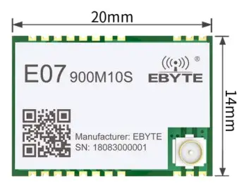
| Size | 14*20mm | – |
| Antenna | IPEX/STAMP | 50-ohm impedance |
| Net Weight | 1.2g | – |
Size and Pin definition
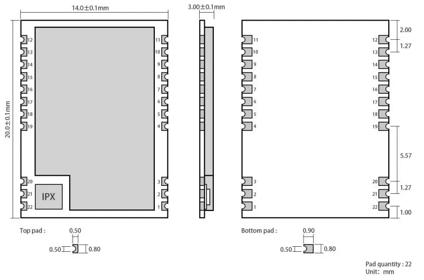
| Pin No. | Item | Direction | Description |
| 1 | GND | Ground wire, connected to the power reference ground | |
| 2 | GND | Ground wire, connected to the power reference ground | |
| 3 | GND | Ground wire, connected to the power reference ground | |
| 4 | GND | Ground wire, connected to the power reference ground | |
| 5 | GND | Ground wire, connected to the power reference ground | |
| 6 | NC | No need to connect | |
| 7 | NC | No need to connect | |
| 8 | NC | No need to connect | |
| 9 | VCC | Power supply, 3.0-3.6V (It is also recommended to add an external ceramic filter capacitor) | |
| 10 | NC | No need to connect | |
| 11 | GND | Ground wire, connected to the power reference ground | |
| 12 | GND | Ground wire, connected to the power reference ground | |
| 13 | NC | No need to connect | |
| 14 | GDO2 | CC1101 chip pins (see CC1101 official user manual for details) | |
| 15 | GOOD | CC1101 chip pins (see CC1101 official user manual for details) | |
| 16 | MISO/GDO1 | Output | SPI master output slave input |
| 17 | MOSI | Input | SPI master input slave output |
| 18 | SCK | Input | Serial Clock Input |
| 19 | CSN | Input | SPI Chip select for starting SPI communication |
| 20 | GND | Ground wire, connected to the power reference ground | |
| 21 | ANT | Input/Output | Antenna, stamp hole (50-ohm impedance) |
| 22 | GND | Ground wire, connected to the power reference ground |
Basic operation
Hardware design
- It is recommended to use a DC stabilized power supply. The power supply ripple factor is as small as possible and the module needs to be reliably grounded;
- Please pay attention to the correct connection of the positive and negative poles of the power supply, the reverse connection may cause permanent damage to the module;
- Please check the power supply to ensure that between the recommended supply voltage, if exceeding the maximum, the module will be permanently damaged;
- Please check the stability of the power supply. Voltage can not fluctuate greatly and frequently;
- When designing the power supply circuit for the module, it is often recommended to reserve more than 30% of the margin, so the whole machine is beneficial for long-term stable operation;
- The module should be as far away as possible from the power supply, transformers, high-frequency wiring, and other parts with large electromagnetic interference;
- Bottom Layer High-frequency digital routing, high-frequency analog routing, and power routing must be avoided under the module. If it is necessary to pass through the module, assume that the module is soldered to the Top Layer, and the copper is spread on the Top Layer of the module contact part(well-grounded), it must be close to the digital part of the module and routed in the Bottom Layer;
- Assuming the module is soldered or placed over the Top Layer, it is wrong to randomly route over the Bottom Layer or other layers, which will affect the module’s spurs and receiving sensitivity to varying degrees;
- It is assumed that there are devices with large electromagnetic interference around the module that will greatly affect the performance. It is recommended to keep them away from the module according to the strength of the interference. If necessary, appropriate isolation and shielding can be done;
- Assume that there are traces of large electromagnetic interference (high-frequency digital, high-frequency analog, power traces) around the module that will greatly affect the performance of the module. It is recommended to stay away from the module according to the strength of the interference. If necessary, appropriate isolation and shielding can be done;
- If the communication line uses a 5V level, a 1k-5.1k resistor must be connected in series (not recommended, there is still a risk of damage);
- The mounting structure of the antenna has a great influence on the performance of the module. It is necessary to ensure that the antenna is exposed, preferably vertically upward. When the module is mounted inside the case, use a good antenna extension cable to extend the antenna to the outside;
- The antenna must not be installed inside the metal case, which will cause the transmission distance to be greatly weakened.
Programming
- It can complete the wireless data transceiving by operating its control register and transceiving buffer. Please refer to the latest CC1101 datasheet for the timing operation of the module register.
- GDO0 is a general-purpose I/O port, see CC1101 user manual;
- GDO2 is generally configured as an IRQ-like function, or not connected. SPI query mode can be used to obtain the interrupt status, but it is still recommended to use external interrupt by connecting to an MCU;
- After CC1101 restores IDLE mode or is configured as sleep mode, it is recommended to reinitialize the power configuration table.
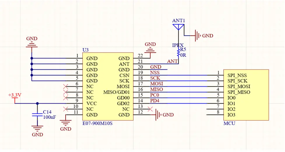
Recommended circuit diagram
FAQ
The communication range is too short
- The communication distance will be affected when obstacle exists;
- Data loss rate will be affected by temperature, humidity, and co-channel interference;
- The ground will absorb and reflect wireless radio waves, so the performance will be poor when testing near the ground;
- Seawater has a great ability in absorbing wireless radio waves, so performance will be poor when testing near the sea;
- The signal will be seriously affected when the antenna is near a metal object or put in a metal case;
- The power register was set incorrectly or the air data rate is set as too high (the higher the air data rate, the shorter the distance);
- The power supply low voltage under room temperature is lower than our recommendation, the lower the voltage, the lower the transmitting power;
- Due to antenna quality or poor matching between antenna and module.
The module is easy to damage
- Please check the power supply source, ensure it is 1.8V~3.6V, a voltage higher than 3.6V will damage the module;
- Please check the stability of the power source, the voltage cannot fluctuate too much;
- Please make sure anti-static operation when installing and using, high-frequency devices have electrostatic susceptibility;
- Please ensure the humidity is within a limited range, some parts are sensitive to humidity;
- Please avoid using modules under too high or too low temperatures.
BER(Bit Error Rate) is high
- There is co-channel signal interference nearby, please be away from interference sources or modify frequency and channel to avoid interference;
- The clock waveform on SPI is not standard, check whether there is interference on the SPI line, and the SPI bus line should not be too long;
- The poor power supply may cause messy code. Make sure that the power supply is reliable;
- The extension line and feeder quality are poor or too long, so the bit error rate is high.
Production guidance
This product is an SMD module. When soldering the module, the soldering personnel must work in accordance with the anti-static operation specification;
This product is an electrostatic-sensitive product. If the module is not welded according to the specification, the module may be permanently damaged.
E07 series
| Model No. | IC | Frequency | Tx power | Distance | Package | Antenna |
| Hz | dBm | m | ||||
| E07-900M1OS | CC1101 | 915M | 10 | 1500 | SMD | STAMP |
| E07-400M1OS | CC1101 | 433M | 10 | 1500 | SMD | STAMP |
| All modules in the E07 series can communicate with each other | ||||||
Antenna Guide
Antenna recommendation
The antenna is an important role in the communication process. A good antenna can largely improve the communication system. Therefore, we recommend some antennas for wireless modules with excellent performance and reasonable prices.
| Model No. | Type | Frequency Hz | Interface | Gain dBi | Length mm | Feeder | Features |
| TX915-XP-100 | Sucker antenna | 915M | SMA-J | 3.5 | 250 | 100cm | Sucker antenna, high gain |
Revision history
| Version | Date | Description | Issued by |
| 1.0 | 2021-06-18 | Initial version | Linson |
About us

http://weixin.qq.com/r/NXTG3t-E_IKHrZu99yEn
Sales hotline:0086-4000-330-990
Technical support:[email protected]
Tel:0086-28-61399028
Website:www.ebyte.com/en
Address: Building B5, Mould Industrial Park, 199# Xi-Qu Ave, West High-tech Zone, Chengdu,611731, Sichuan, China
FCC Caution:
Any changes or modifications not expressly approved by the party responsible for compliance could void the user’s authority to operate the equipment.
This device complies with part 15 of the FCC Rules. Operation is subject to the following two conditions: (1)
This device may not cause harmful interference, and (2) this device must accept any interference received, including interference that may cause undesired operation.
FCC RF Radiation Exposure Statement:
- This Transmitter must not be co-located or operating in conjunction with any other antenna or transmitter.
- This equipment complies with RF radiation exposure limits set forth for an uncontrolled environment.
- This equipment should be installed and operated with a minimum distance of 20cm between the radiator& your body.
| Antenna Manufacturer: | CHENGDU ZIISOR TECHNOLOGY CO., LTD. |
| Antenna Model: | TX915-XP-100 |
| Antenna type: | Sucker antenna |
| Antenna gain: | 3.5dBi |
Host product manufacturers need to provide a physical or e-label stating, “Contains FCC ID: 2ALPH-E07900M10S” with their finished product.
Only those antennas with the same type and lesser gain filed under this FCC ID can be used with this device.
The host product manufacturer is responsible for compliance with any other FCC rules that apply to the host not covered by the modular transmitter grant of certification. The final host product still requires Part 15 Subpart B compliance testing with the modular transmitter installed.
The final host integrator must ensure there is no instruction provided in the user manual or customer documentation indicating how to install or remove the transmitter module except such device has implemented two-way authentication between the module and the host system.
The final host manual shall include the following regulatory statement: This equipment has been tested and found to comply with the limits. This device complies with Part 15 of the FCC Rules. Operation is subject to the following two conditions: (1) This device may not cause harmful interference, and (2) this device must accept any interference received, including interference that may cause undesired operation.
This module has been tested and found to comply with part 15.247 requirements for Modular Approval.
This module is intended for OEM integrators. The OEM integrator is responsible for compliance to all the rules that apply to the product into which this certified RF module is integrated. Additional testing and certification may be necessary when multiple modules are used.
FCC Statement
This device complies with part 15 of the FCC Rules. Operation is subject to the following two conditions: (1) This device may not cause harmful interference, and (2) this device must accept any interference received, including interference that may cause undesired operation.
Any changes or modifications not expressly approved by the party responsible for compliance could void the user’s authority to operate the equipment.
This equipment should be installed and operated with a minimum distance of 20mm between the radiator and your body.
This equipment has been tested and found to comply with the limits for a Class B digital device, pursuant to Part 15 of the FCC Rules. These limits are designed to provide reasonable protection against harmful interference in a residential installation. This equipment generates uses and can radiate radio frequency energy and, if not installed and used in accordance with the instructions, may cause harmful interference to radio communications. However, there is no guarantee that interference will not occur in a particular installation.
If this equipment does cause harmful interference to radio or television reception, which can be determined by turning the equipment off and on, the user is encouraged to try to correct the interference by one or more of the following measures:
- Reorient or relocate the receiving antenna.
- Increase the separation between the equipment and receiver.
- Connect the equipment into an outlet on a circuit different from that to which the receiver is connected.
- Consult the dealer or an experienced radio/TV technician for help.
Copyright ©2012–2021, Chengdu Ebyte Electronic Technology Co., Ltd.
References
 📧[email protected]
-
Chengdu Ebyte Electronic Technology Co.,Ltd
-
ZigBee_LoRa_串口服务器_数传电台dtu_蓝牙WiFi【GPRS_nbiot_cat】无线通信模块_成都亿佰特电子科技有限公司
-
LoRa/zigbee/WiFi/蓝牙模块/4G DTU网关/数传电台/串口服务器/遥控开关/无线通信模块-亿佰特电子科技有限公司
-
E07-868MS10 CC1101 SPI射频模块-RF射频模块,lora,射频(SPI/SOC)模块,射频(UART)模块,物联网应用,无线数传模块
-
E07-M1101S CC1101 SPI射频模块-RF射频模块,lora,射频(SPI/SOC)模块,射频(UART)模块,物联网应用,无线数传模块


