![]()
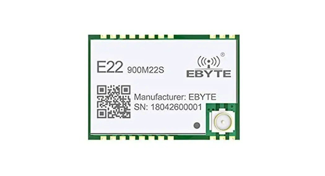
E22-900M22S User Manual
SX1262 868/915 MHz SPI SMD LoRa Module
Chengdu Ebyte Electronic Technology Co., LTD.
Disclaimer
EBYTE reserves all rights to this document and the information contained herein. Products, names, logos, and designs described herein may in whole or in part be subject to intellectual property rights. Reproduction, use, modification, or disclosure to third parties of this document or any part thereof without the express permission of EBYTE is strictly prohibited. The information contained herein is provided “as is” and EBYTE assumes no liability for the use of the information. No warranty, either express or implied, is given, including but not limited, with respect to the accuracy, correctness, reliability, and fitness for a particular purpose of the information. This document may be revised by EBYTE at any time. For most recent documents, visit www.ebyte.com.
Overview
Introduction
The E22-900M22S is based on the SX I262, a new generation of LoRa”4 RF chip manufactured by Semtech, USA. It is an ultra-small and self-developed 868MHz, 915MHz SMD LoRaTm wireless module.
Because it adopted the original SX1262 as the main core, the anti-interference performance and communication distance have been further improved compared to the previous generation LoRaTM transceiver. Due to its new LoRaTM modulation technology, the anti-interference performance and communication distance are far superior to the current FSK and GFSK modulation products. This module is mainly for smart homes, wireless meter reading, scientific and medical research, and long-distance wireless communication equipment. The RF performance and components selection are all in accordance with industrial-grade standards and this product obtained FCC, CE, and RoHS certification already so users do not need to worry about the performance. Adopted industrial grade high precision 32MHz crystal, the product can cover an ultra-wide frequency range of 850-930MHz and is backward compatible with SX 1278 and SX1276.
Since the module is an RF transceiver module only, users need to use the MCU driver or use a dedicated SPI debug tool
Features
- Communication distance tested is up to 7km ;
- The maximum transmission power of 160mW, software multi-level adjustable ;
- Support the global license-free ISM 868/915MHz band;
- Support air date rate of 0.018-62.5kbps in the Laing mode ;
- Support 300kpbs in the FSK mode,
- Compatible with the transceiver of SX1278/SX1276;
- With large capacity, FIFO supports 256Byte data cache.;
- New SF5 spreading factor to support dense networks;
- Support 2.5V-3.7V power supply, more than 3.3V power supply can guarantee the best performance;
- Industrial grade standard design, support -40 — 85 °C for working over a long time ;
- IPEX and stamp holes are optional, which is convenient for secondary development and integration.
Application
- Home security alarm and remote keyless entry;
- Smart home and industrial sensors ;
- Wireless alarm security system ;
- Building automation solutions ;
- Wireless industrial-grade remote control;
- Health care products;
- Advanced Meter Reading Architecture(AMI) ,
- Automotive industry applications.
Specification and parameter
Limit parameter
| Main parameter | Performance | Remark | |
| Min. | Max. | ||
| Power supply (V ) | 0 | 4. | Voltage over 3.7V will cause permanent damage to module |
| Blocking power ( dBm) | 10 | Chances of burn is slim when modules are used in short distance | |
| Operating temperature (°C) | -40 | 85 | |
Operating parameter
| Main parameter | Performance | Remark | |||
| N lin. | Typ. | Max. | |||
| Operating voltage (V) | 2. | 3. | 4. | It’s recommended to use 3.3V. | |
| Communication level ( V) | 3. | For 5V TTL, It is recommended to add level conversion | |||
| Operating temperature (°C) | -40 | – | 85 | Industrial design | |
| Operating frequency ( GHz ) | 850 | 868/915 | 930 | Support ISM band | |
| Power consumption | TX current ( mA ) | 119 | Instant power consumption | ||
| RX current ( mA) | 7. | ||||
| Sleep current ( nA ) | 180 | Software is shut down | |||
| Max Tx Power (dBm) | 21. | 22. | 22. | ||
| Receiving sensitivity (dBm) | -144 | -146 | -147 | Air data rate is 0.3kbps | |
| Air data rate (bps) | 0.6k | – | 300k | Controlled via user’s programming | |
| 0.018k | 62.5k | Controlled via user’s programming | |||
| Main parameter | Description | Remark |
| Distance for reference | 7000m | Test condition : clear and open area, antenna gain: 5dBi, antenna height: 2.5m, air data rate: 0.3kbps |
| FIFO | 256Byte | The maximum length of a single transmission |
| Crystal frequency | 32MHz | |
| Modulation | Lora(recommended) | |
| Package | SMD | |
| Connector | 1.27mm | Stamp hole |
| Communication interface | SPI | 0-10Mbps |
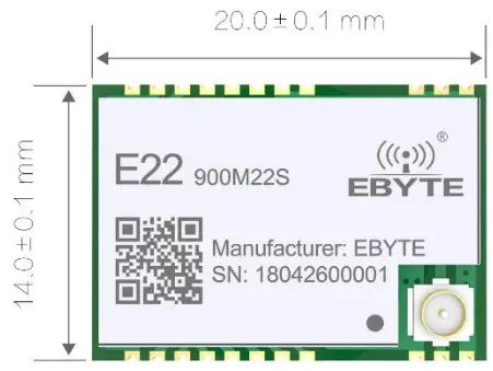
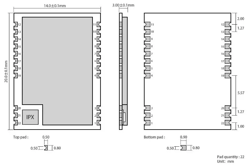
| Size | 20* 14*2.8 mm | |
| Antenna | IPEXIIPEX | 50-ohm impedance |
Size and pin definition
| No. | Name | Direction | Function |
| I | GND | Ground wire, connected to the power reference ground | |
| GND | Ground wire, connected to the power reference ground | ||
| 3 | GND | Ground wire, connected to the power reference ground | |
| 4 | GND | Ground wire, connected to the power reference ground | |
| GND | Ground wire, connected to the power reference ground | ||
| 6 | RXEN | Input | RF switch receiving control pin, connected to external microcontroller 10, valid in high level |
| 7 | TXEN | Input | RF switch transmitting control pin, connected to external microcontroller 10 or DIO2, valid in high level |
| 8 | D102 | Input/Output | Configurable universal 10 port (see SX1262 manual for details) |
| 9 | VCC | Power supply, 1.8-3.7V(It is recommended to add external ceramic filter capacitor) | |
| 10 | GND | Ground wire, connected to the power reference ground | |
| 11 | GND | Ground wire, connected to the power reference ground | |
| 12 | GND | Ground wire, connected to the power reference ground | |
| 13 | D101 | Input/Output | Configurable universal 10 port (see SX1262 manual for details) |
| 14 | BUSY | Output | For status indication (see SX1262 manual for details) |
| 15 | NRST | Input | Chip reset trigger input pin, valid in low level |
| 16 | MISO | Output | SPI data output pin |
| 17 | MOSI | Input | SPI data output pin |
| 18 | SCK | Input | SPI data output pin |
| 19 | NSS | Input | Module chip select pin for starting an SPI communication |
| 20 | GND | Ground wire, connected to the power reference ground | |
| 21 | ANT | Antenna interface, stamp hole (50-ohm characteristic impedance) | |
| 22 | GND | Ground wire, connected to the power reference ground |
Basic Operation
Hardware Design
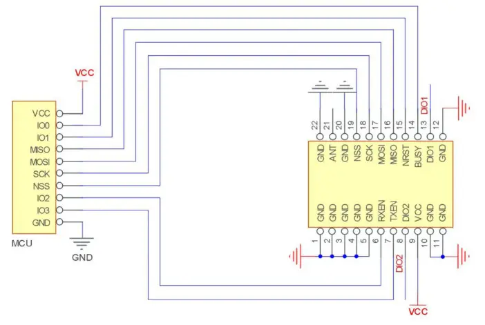
| SN | Brief Connection between Module and Single Chip Microcomputer |
| 1 | The MO, 101, 102, 103 in MCU means the 10 port of MCU. |
| 2 | D101, D102 is the normal I0 port, which can be configured to multiple functions. The DIO2 can connect with TXEN. but not with the 10 ports of MCU. It’s used to control RF switch, see more details in SX1262 datasheet. Also, It can be floated when not in use. |
| 3 | The DI03 is powered by a 32MHz TCXO crystal. |
| 4 | Ensure the good grounding, large area of paving, small the power supply ripple, the filter capacitor should be increased and as close as possible to the VCC and GND pins of the module. |
Note:
- It is recommended to use DC stabilized power supply to supply power to the module. The power supply ripple coefficient is as small as possible, and the module needs to be reliably grounded.
- Please pay attention to the correct connection of the positive and negative poles of the power supply. If the reverse connection is connected, the module may be permanently damaged.
- Please check the power supply to ensure that between the recommended supply voltage, if exceeding the maximum, the module will be permanently damaged.
- Please check the stability of the power supply, the voltage can not be significantly frequent.
- When designing the power supply circuit for the module, it is often recommended to reserve more than 30% of the margin, and the whole machine is beneficial for long-term stable operation.
- The module should be as far away as possible from the power supply, transformers, high-frequency wiring, and other parts with large electromagnetic interference.
- High-frequency digital traces, high-frequency analog traces, and power traces must be avoided under the module. If it is necessary to pass through the module, assume that the module is soldered to the Top Layer, and the copper is spread on the Top Layer of the module contact part(All copper-covered and well-grounded), and must be close to the digital part of the module and routed in the Bottom Layer.
- Assuming the module is soldered or placed in the Top Layer, it is also wrong to randomly route the Bottom Layer or other layers, which will affect the module’s spurs and receiving sensitivity to varying degrees.
- Assume that there are traces with large electromagnetic interference around the module (high-frequency digital, high-frequency analog, power trace), which will greatly affect the performance of the module. It is recommended to stay away from the module according to the strength of the interference. If necessary, appropriate isolation and shielding can be done;
- If the communication line uses a 5V level, an lk-5.1k resistor must be connected in series (not recommended, there is still a risk of damage).
- Try to stay away from some physical layers and also have a 2.4GHz TTL protocol, for example, USB3.0
- The antenna mounting structure has a great influence on the performance of the module. It is necessary to ensure that the antenna is exposed, preferably vertically upward. When the module is mounted inside the case, use a good antenna extension cable to extend the antenna to the outside of the case.
- The antenna must not be installed inside the metal case, which will greatly reduce the transmission distance.
- It is recommended to add a 200R protection resistor to the RXDITXD of the external MCU.
Software Programming
- Its driving mode is exactly the same as SX1268/SX1262. Users can operate according to SX1268/SX1262 chip datasheet.
- D101 and DIO2 are general-purpose 10 ports, which can be configured into multiple functions. D102 can be connected to TXEN and not connected to the MCU’s 10 port. It can be used to control the RF switch transmission. If not used, you can hang it. For details, see the SXI262 manual.
- DIO 3 is used to supply 32 MHz TCXO crystal oscillators.
FAQ
The communication range is too short
- The communication distance will be affected when an obstacle exists.
- Data loss rate will be affected by temperature, humidity, and co-channel interference.
- The ground will absorb and reflect wireless radio waves, so the performance will be poor when testing near the ground.
- Seawater has a great ability in absorbing wireless radio waves, so performance will be poor when testing near the sea.
- The signal will be affected when the antenna is near a metal object or put in a metal case.
- The power register was set incorrectly, the air data rate is set as too high (the higher the air data rate, the shorter the distance).
- When the power supply at room temperature is lower than the recommended low voltage, the lower the voltage is, the lower the transmitting power is.
- Due to antenna quality or poor matching between antenna and module.
The module is easy to damage
- Please check the power supply and ensure it is within the recommended range. Voltage higher than the peak will lead to permanent damage to the module.
- Please check the stability of the power supply and ensure the voltage does not fluctuate too much.
- Please make sure anti-static measures are taken when installing and using, high-frequency devices that have electrostatic susceptibility.
- Please ensure the humidity is within a limited range for some parts are sensitive to humidity.
- Please avoid using modules under too high or too low temperatures.
The high bit error rate
- There is co-channel signal interference nearby, keep away from interference sources or modify the frequency, channels to avoid interference.
- The clock waveform on the SPI is not standard. Check whether there is interference on the SPI line. The SPI bus line should not be too long.
- The unsatisfactory power supply may also cause garbled characters, and ensure the reliability of the power supply.
- If the extension cable or feeder is of poor quality or too long, the bit error rate will be high.
Welding operation guidance
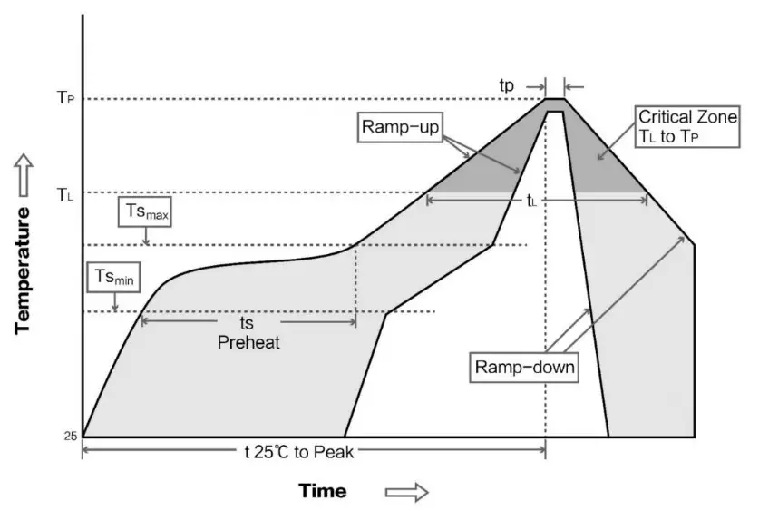
Reflow Soldering Temperature
| Profile Feature | Curve feature | Sn-Pb Assembly | Pb-Free Assembly |
| Solder Paste | Solder paste | Sn63/Pb37 | Sn96.5/Ag3/Cu0.5 |
| Preheat Temperature min (Tsmin) ) | Minimum preheating temperature | 100°C | 150°C |
| Preheat temperature max (Tmax) | Maximum preheating temperature | 150°C | 200°C |
| Preheat Time (Tasmin to Tsmax)(ts) | Preheating time | 60-120 sec | 60-120 sec |
| Average ramp-up rate(Tmax to Tp) | Average rising rate | 3°C/second max | 3°C/second max |
| Liquidous Temperature (TL) | Liquid phase temperature | 183°C | 217°C |
| Time ( tL) Maintained Above (TL) | Time above liquidus | 60-90 sec | 30-90 sec |
| Peak temperature (Tp) ) | Peak temperature | 220-235°C | 230-250°C |
| Average ramp-down rate (Tp to Tsmax) | Average descent rate | 6°C/second max | 6°C/second max |
| Time 25°C to peak temperature | Time of 25 ° C to peak temperature | 6 minutes max | 8 minutes max |
Reflow Soldering Curve
| Model | Chip | Frequency Hz | Transmit power dBm | Test distance km | Packaging | Size mm | Communication Interface |
| E22- 900T22S | SX1262 | 868M 915M | 22 | 7 | SMD | 16*26 | UART |
| E22- 230T22S | SX1262 | 230M | 22 | 7 | SMD | 16*26 | UART |
| E22- 400T22S | SX1268 | 433M 470M | 22 | 7 | SMD | 16*26 | UART |
| E22- 400M30S | SX1268 | 433M 470M | 30 | 12 | SMD | 24*38.5 | SPI |
| E22- 900M30S | SX1262 | 868M 915M | 30 | 12 | SMD | 24*38.5 | SPI |
| E22- 900M22S | SX1262 | 868M 915M | 22 | 6.5 | SMD | 14*20 | SPI |
| E22- 400M22S | SX1268 | 433M 470M | 22 | 6.5 | SMD | 14*20 | SPI |
Antenna Type
Antenna recommendation
The antenna plays an important role in the communication process. The inferior antenna often has a great impact on the communication system. Therefore, we recommend some antennas that support our wireless modules and have excellent performance and reasonable prices.
| Product | Type | Frequent y Hz | Interface | Gain dBi | Size | Feeder | Features |
| TX433-NP-4310 | Soft PCB antenna | 433M | SMA-J | 2 | 43.8*9.5mm | – | Built-in flexible FPC son antenna |
| TX433-JW-5 | Soft PCB antenna | 433M | SMA-J | 2 | 50mm | – | Flexible, Omnidirectional |
| TX411-JWCi-7 | Soft PCB antenna | 433M | SMA-J | 3. | 75mm | – | Flexible, Omnidirectional |
| TX433-JK-20 | Soft PCB antenna | 433M | SMA-J | 3 | 210mm | – | Flexible, Omnidirectional |
| TX433-JK-I 1 | Soft PCB antenna | 433M | SMA-J | 3. | 110mm | – | Flexible, Omnidirectional |
| TX433-XP-200 | Sucker antenna | 433M | SMA-J | 4 | 19cm | 200cm | High Gain |
| TX433-XP-I00 | Sucker antenna | 433M | SMA-J | 4. | 18.5cm | 100cm | High Gain |
| rX413-XPH-100 | Sucker antenna | 433M | SMA-J | 6 | 96.5cm | 300cm | High Gain |
| TX413-.17.6-6 | Soft PCB antenna | 433M | SMA-J | 3. | 52mm | – | Ultra short straight, Omnidirectional |
| TX433-JZ-5 | Soft PCB antenna | 433M | SMA-J | 2 | 52mm | – | Ultra short straight, Omnidirectional |
| 1X490-XP-100 | Sucker antenna | 490M | SMA-J | 50 | 12cm | 100cm | High Gain |
| TX490-JZ-5 | Soft PCB antenna | 490M | SMA-J | 50 | 50mm | – | High Gain |
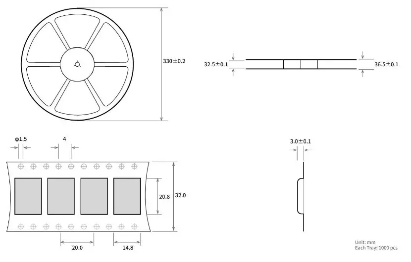
Batch packaging
Revision history
| Version | Date | Description | Issued by |
| 1.0 | 2018-09-25 | Original version | huaa |
| 1.1 | 2019-02-17 | Content added | Ray |
| 1.2 | 2019-04-03 | Content updated | Ray |
| 1.3 | 2019-11-14 | Ren | |
| 1.4 | 2020-11-26 | Error correction | Linson |
About history
Website: www.ebyte.com
Sales: [email protected]
Support: [email protected]
Tel: +86-28-61399028 Ext. 812
Fax: +86-28-64146160
adress: Innovation Center B333—D347, 4# XI-XIN road,High-tech district (west), Chengdu, Sichuan, China![]() Chengdu Ebyte Electronic Technology Co.,Ltd.
Chengdu Ebyte Electronic Technology Co.,Ltd.


