![]()
![]()
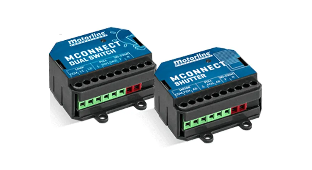
PROFESSIONAL TO644347 Mconnect Dual Switch
User Manual 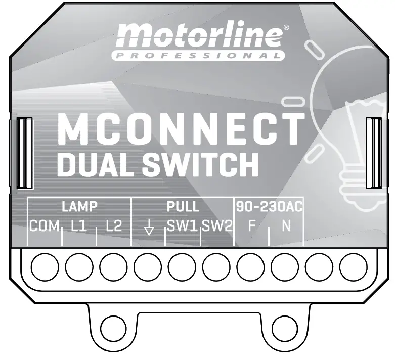
MCMOCNONNNEECCT TDUAL SWITCH
USER’S AND INSTALLER’S MANUAL
v1.2 REV. 01/2022
SAFETY INSTRUCTIONS
ATTENTION: This product is certified in accordance with European Community (EC) safety standards.
ROHS
This product complies with Directive 2011/65/EU of the European Parliament and of the Council, of 8 June 2011, on the restriction of the use of certain hazardous substances in electrical and electronic equipment and with Delegated Directive (EU) 2015/863 from Commission.![]() (Applicable in countries with recycling systems). This marking on the product or literature indicates that the product and electronic accessories (eg. Charger, USB cable, electronic material, controls, etc.) should not be disposed of as other household waste at the end of its useful life. To avoid possible harm to the environment or human health resulting from the uncontrolled disposal of waste, separate these items from other types of waste and recycle them responsibly to promote the sustainable reuse of material resources.
(Applicable in countries with recycling systems). This marking on the product or literature indicates that the product and electronic accessories (eg. Charger, USB cable, electronic material, controls, etc.) should not be disposed of as other household waste at the end of its useful life. To avoid possible harm to the environment or human health resulting from the uncontrolled disposal of waste, separate these items from other types of waste and recycle them responsibly to promote the sustainable reuse of material resources. Home users should contact the dealer where they purchased this product or the National Environment Agency for details on where and how they can take these items for environmentally safe recycling. Business users should contact their vendor and check the terms and conditions of the purchase agreement. This product and its electronic accessories should not be mixed with other commercial waste.
![]() This marking indicates that the product and electronic accessories (eg. charger, USB cable, electronic material, controls, etc.) are susceptible to electric shock by direct or indirect contact with electricity. Be cautious when handling the product and observe all safety procedures in this manual
This marking indicates that the product and electronic accessories (eg. charger, USB cable, electronic material, controls, etc.) are susceptible to electric shock by direct or indirect contact with electricity. Be cautious when handling the product and observe all safety procedures in this manual
GENERAL WARNINGS
- This manual contains very important safety and usage information. very important. Read all instructions carefully before beginning the installation/usage procedures and keep this manual in a safe place that it can be consulted whenever necessary.
- This product is intended for use only as described in this manual. Any other enforcement or operation that is not mentioned is expressly prohibited, as it may damage the product and put people at risk of causing serious injuries.
- This manual is intended firstly for specialized technicians and does not invalidate the user’s responsibility to read the “User Norms” section in order to ensure the correct functioning of the product.
- The installation and repair of this product may be done by qualified and specialized technicians, to assure every procedure is carried out in accordance with applicable rules and norms. Nonprofessional and inexperienced users are expressly prohibited from taking any action unless explicitly requested by specialized technicians to do so.
- Installations must be frequently inspected for unbalance and the wear signals of the cables, springs, hinges, wheels, supports, and other mechanical assembly parts.
- Do not use the product if it is necessary to repair or if an adjustment is required.
- When performing maintenance, cleaning, and replacement of parts, the product must be disconnected from the power supply. Also includes any operation that requires opening the product cover.
- The use, cleaning, and maintenance of this product may be carried out by any persons aged eight years old and over and persons whose physical, sensorial or mental capacities are lower, or by persons without any knowledge of the product, provided that these are supervision and instructions given by persons with experience in terms of usage of the product in a safe manner and who understands the risks and dangers involved.
- Children shouldn’t play with the product or opening devices to avoid the motorized door or gate from being triggered involuntarily.
WARNINGS FOR TECHNICIANS
- Before beginning the installation procedures, make sure that you have all the devices and materials necessary to complete the installation of the product.
- You should note your Protection Index (IP) and operating temperature to ensure that is suitable for the installation site.
- Provide the manual of the product to the user and let them know how to handle it in an emergency.
- If the automatism is installed on a gate with a pedestrian door, a door locking mechanism must be installed while the gate is in motion.
- Do not install the product “upside down” or be supported by elements that do not support its weight. If necessary, add brackets at strategic points to ensure the safety of the automatism.
- Do not install the product in an explosive site.
- Safety devices must protect the possible crushing, cutting, transport, and danger areas of the motorized door or gate.
- Verify that the elements to be automated (gates, door, windows, blinds, etc.) are in perfect function, aligned, and level. Also, verify if the necessary mechanical stops are in the appropriate places.
- The center must be installed in a safe place from any fluid (rain, moisture, etc.), dust, and pests.
- You must route the various electrical cables through protective tubes, to protect them against mechanical exertions, essentially on the power supply cable. Please note that all the cables must enter the center from the bottom.
- If the automatism is to be installed at a height of more than 2,5m from the ground or other level of access, the minimum safety and health requirements for the use of work equipment workers at the work of Directive 2009/104/CE of European Parliament and of the Council of 16 September 2009.
- Attach the permanent label for the manual release as close as possible to the release mechanism.
- Disconnect means, such as a switch or circuit breaker on the electrical panel, must be provided on the product’s fixed power supply leads in accordance with the installation rules.
- If the product to be installed requires a power supply of 230Vac or 110Vac, ensure that the connection is to an electrical panel with a ground connection.
- The product is only powered by low voltage satisfy with central (only at 24V motors)
WARNINGS FOR USERS
- Keep this manual in a safe place to be consulted whenever necessary.
- If the product has contact with fluids without being prepared, it must immediately disconnect from the power supply to avoid short circuits, and consult a specialized technician.
- Ensure that technician has provided you with the product manual and informed you how to handle the product in an emergency.
- Ifthesystemrequiresanyrepairormodification,unlocktheautomatism, turn off the power, and do not use it until all safety conditions have been met.
- In the event of tripping of circuit breakers or fuse failure, locate the malfunction and solve it before resetting the circuit breaker or replacing the fuse. If the malfunction is not repairable by consulting this manual and contact a technician.
- Keep the operation area of the motorized gate free while the gate is in motion, and do not create strength to the gate movement.
- Do not perform any operation on mechanical elements or hinges if the product is in motion.
RESPONSIBILITY
- Supplier disclaims any liability if:
- Product failure or deformation results from improper installation use or maintenance!
- Safety norms are not followed in the installation, use, and maintenance of the product.
- Instructions in this manual are not followed.
- Damaged is caused by unauthorized modifications · In these cases, the warranty is voided.
SYMBOLS LEGEND:
 | · Important safety notices |
 | · Useful information |
| · Programming information | |
| · Potentiometer information | |
| · Connectors information | |
| · Buttons information |
CONNECTIONS SCHEME
CONNECTION TO WALL SWITCH OF 2 KEYS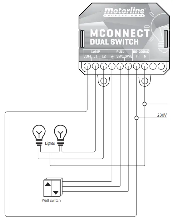
CONTROL BOARD
CONNECT DUAL SWITCH
The CONNECT DUAL SWITCH was developed to control up to two lamps remotely or by pushbutton, using the CONNECT App and a module previously connected to the application. Its small size allows installation inside junction boxes, existing behind electrical switches (push buttons).
Advantages of using CONNECT:
- Easy installation and configuration;
- Possibility to control the lights in your home from anywhere;
- Reading the status of lights;
- Possibility of creating intelligent scenarios, which allow triggering a series of functions with a simple click or by voice control;
- Possibility of configuring routines for the devices (example: turn on the lights at 10 am and turn off at 10.30 am).
GRAPHIC DESCRIPTION
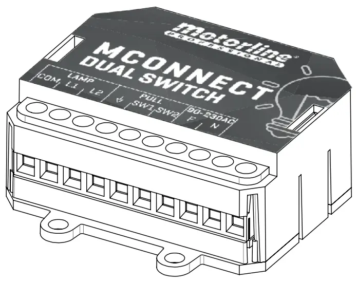
| LAMP | COM | Lights Output – Common |
| LI. | Lamp output 1 | |
| L2 | Lamp output 2 | |
| PULL | 4 | Wall switch connection – Common |
| SW1 | Wall switch connection – Lamp 1 | |
| SW2 | Wall switch connection – Lamp 2 | |
| 90-230AC | F | 230V line input (phase) |
| N | 230V line input (neutral) |
| 5031 | • Flash in purple | Pairing mode (It is waiting to be added) |
| •Red | No network | |
| •Flash in red | Lost connection to the cloud | |
| •Blue | Successfully connected to the local network, but not yet connected to the cloud | |
| •Flash in blue | Upgrading Firmware | |
| •Green | Connected to the cloud |
CONTROL BOARD
TECHNICAL SPECIFICATIONS

| Power Supply | 90-230 Vac 50-60Hz |
| Maximum light power | 230Vac; 1000W |
| Output relay capacity | 5A 250VAC 5A 30VDC |
| Consumption | 15mA @ 230AC |
| Operating temperature | -20°C to 70°C |
| Module Frequency | 2.4 GHz |
| Input | 2 contact inputs without tension |
| Output | 2 relay outputs without tension |
| Technology | WIFI IEEE 802.11b/g/n, Bluetooth |
| Wifi access | 50m in open country |
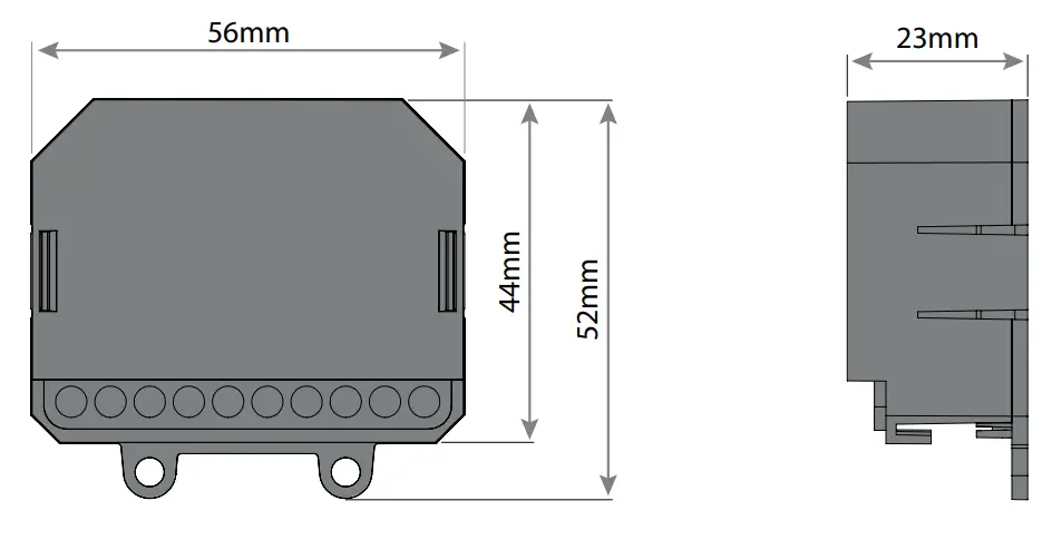
| Protection level | IP44 |
| Construction material | ABS |
- The existence of a Wi-Fi network is required in the space where the device will be working;
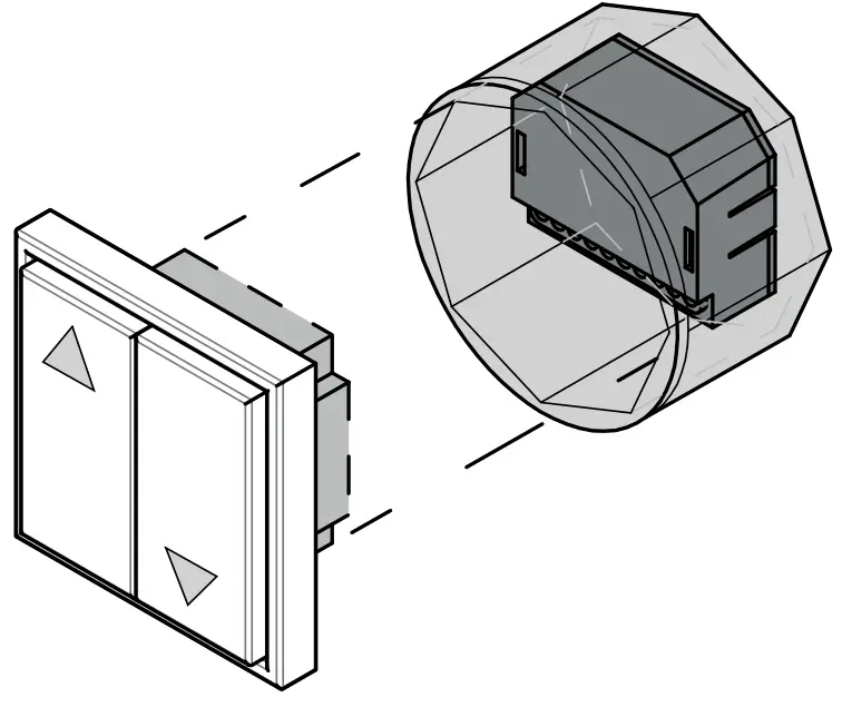
- The device must be installed behind a normal switch, inside the junction box, passing all light control to be performed by the device.
INSTALLATION
PRODUCT INSTALLATION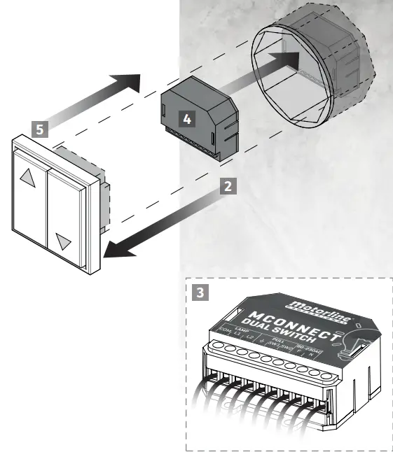
- Turn off the general lights of the house on the electrical panel.
- Disassemble the switch plate and disconnect all wires.
- Connect module wires to the installation wires (see page 4A).
- Insert the CONNECT DUAL SWITCH module inside the junction box.
- Replace the switch plate and tighten it completely.
CONFIGURATION
OPERATION SETTINGS
SWITCH MODE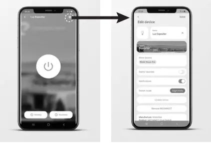
- PULSE Changes the state whenever the pulse switch is pressed.
- EDGE MODE Changes the state (ON or OFF) whenever the switch changes position. Ex: If the wall switch is in the OFF position and the light is ON, changing the switch to the ON position will turn the light OFF.
- FOLLOWING MODE It changes the state depending on the position of the switch, it works like a normal switch. Ex: If the wall switch is in the OFF position and the light is ON, switching the switch to the ON position will not change the light status. If you change it back to the OFF position then it will turn off the light.
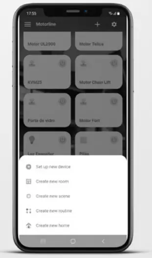
ADD MODULE IN IN THE APP
- Open CONNECT app.
- Login
- On the home page press the “+” button at the top right.
- Press Add new CONNECT.
- Accept all requested permissions.
- Turn on the power.

- Check that the module is in pairing mode (flashing purple).
Note · if it is not in pairing mode it is necessary to reset - Read the QR Code on the module box.
- If you prefer or don’t have the QR Code, can change the button to Scan nearby and select the module in the devices found.
- Enter the name and password of the Wifi network you are connected to.
- Wait for add process be complete.
REMOVE MODULE FROM THE APP
- Press on the device you want to remove.
- Press on the icon with a gear symbol on the upper right side of the screen.
- Press Remove MCONNECT.
- Confirm.
RESET
When resetting, the device is no longer connected to the account it is associated with in the application.
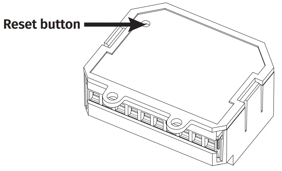 Press the reset button until the LED changes to pairing mode (flashing purple), which will confirm the successful operation.
TROUBLESHOOTING
INSTRUCTIONS FOR FINAL CONSUMERS/TECHNICIANS
| PROBLEM | SOLUTION |
| The LED reader does not light up | Check that the power is connected correctly. |
| The module is not in pairing mode (LED flashing purple) and I haven’t configured it yet | Press the Reset button located on the back of the module, until it switches to pairing mode. |
| The module has the red LED | Make sure the network you configured the module on is available. Check if you have coverage of the network to which the module is connected. Check if the network you have configured the module has Internet access. |
| The module has the blue LED | Check if the network you configure the module has Internet access. |
| The output does not change state | Check that the connections are correct. |
| The switch does not change the state output | Make sure the connections are correct. Check the App to confirm the switch mode is in the correct mode. |
![]()


