Maiwe MIGE2210-2GT Industrial Ethernet Switch User Manual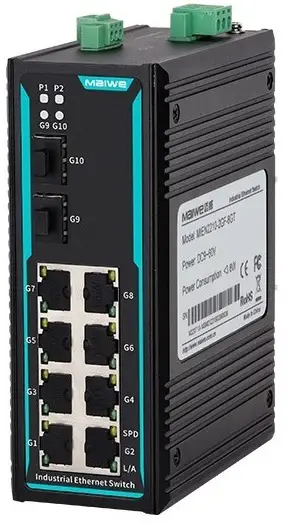
Packing list
The package of this switch contains the following items. If any item is found to be missing or damaged, please contact the agent or the customer service center of Maiwe for assistan.
Items | Quantity | Remarks |
Industrial Ethernet Switch | 1PCS | |
| Power cord | 1PCS | AD220 model only |
| User Manual | 1PCS |
Product description
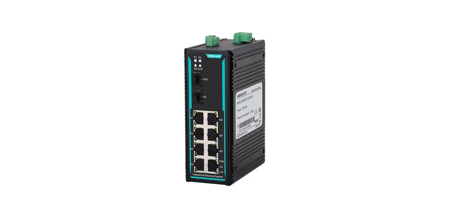
This switch is a managed DIN RAIL industrial Ethernet switch. MIGE2210 series switches provide 10 ports (2 fiber ports and 8 copper ports). Among them, MIGE2210- 2GT (8 100MBase-FX and 2 10/100/1000MBase-TX interfaces); MIGE2210-2GF (8 10/100MBase-TX and 2 1000MBase-FX interfaces); MIGE2210-2GF-4F (4 10/100MBase-TX and 4 100MBase-FX and 2 1000MBase-FX interfaces).
MIGE2210-2GT 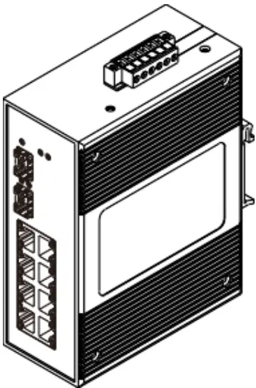
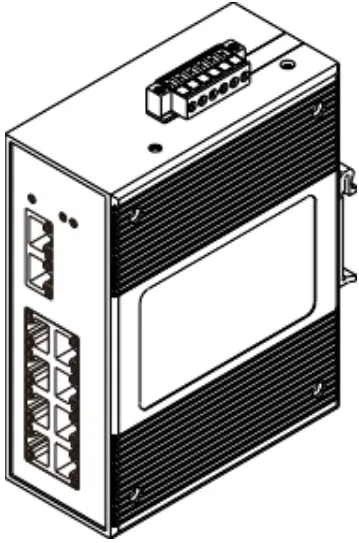
MIGE2210-2GF 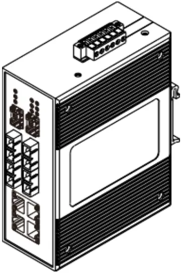
MIGE2210-2GF-4F
Interface description
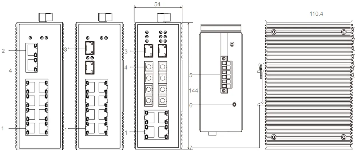
NO. | Description |
1 | 10/100MBase-TX interface |
2 | 10/100/1000MBase-TX interface |
3 | 1000MBase-FX interface |
4 | 10/100MBase-FX interface |
5 | Power input terminal |
| 6 | Ground screw |
7 | DIN RAIL kit |
The indicator description of the switch is shown in the following table.
| Indicator lights | Status | Definition |
SystemStatus LED | ||
PWR1/PWR2 | On | The power is connected and operating normally |
Off | The power is not connected or the system is not operating normally | |
RUN | Flashing | The system is operating normally (some models are always on to indicate normally |
Off | The system is not working properly | |
Gigabit RJ45 Port Status LED | ||
10M100M1000M | On | 1000M working status |
Off | 100M working status | |
L/A (Green) | On | The port has established a valid network connection |
Flashing | There is network activity on the port | |
Off | No valid network connection is established on the port | |
Gigabit SFP Port Status LED | ||
| 10M100M1000M (Green) | On | 1000M working status |
| Off | 100M working status | |
100M Fiber Port Status LED | ||
LINK | On | The port has established a valid network connection |
Flashing | There is network activity on the port | |
Off | No valid network connection is established on the port | |
100M RJ45 Port Status LED | ||
| Each RJ45 port has two indicator lights, the yellow light is the port plastic rate indicator, the green light is the port connection status indicator. | ||
10/100M (Yellow) | On | 100M working state (namely 100Base-TX) |
Off | 10M working status (namely 10Base-T) | |
Link/Act | On | The port has established a valid network connection |
Flashing | There is network activity on the port | |
Off | No valid network connection is established on the port | |
Power Connection
This series of switches can be configured for DC12~48V, DC48V, and AD220V input. It uses 5.08mm pitch lock terminals to connect to 2 power inputs. When the input is AD220V, only the PWR1 power port is valid.
This series of switches supports the power-down alarm function. When the switch is powered normally, the normally closed contact of the relay is open. When the switch has no power input or the input power is abnormal, the relay contact is closed. The relay contact output can be used to connect other sound and light alarm devices.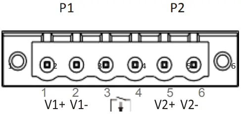
No. | Pin definition |
1 | Power 1 input V+ |
2 | Power 1 input V- |
3,4 | Alarm relay output normally open |
5 | Power 2 input V+ |
6 | Power supply 2 input V- |
Hardware installation
![]() Installation Precautions
Installation Precautions
To prevent equipment damage or personal injury caused by improper use, observe the following precautions:
- During the installation process, you need to wear anti-static gloves or anti-static gloves, and power-off the switch.
- Please make sure that the input voltage is within the input voltage range marked on the switch.
- The transmission distance has a certain relationship with the connected wire. It is recommended to use a standard Cat5e/6 network cable.
- The equipment must be grounded for lightning protection, otherwise the protection level of the equipment will be greatly reduced; please use a wire of No. 20 or more to connect the grounding terminal to the ground.
- The power line, ground line and signal line are laid out separately and the distance is not less than 5cm.
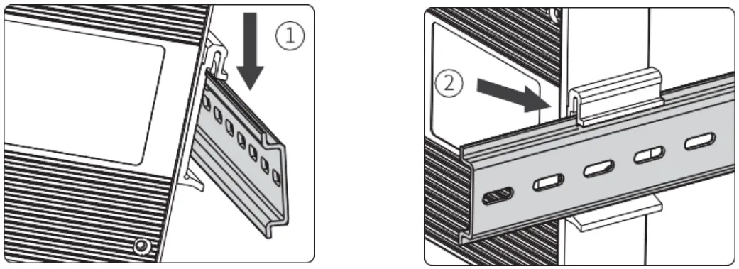
Device installation
- Tilt the switch upwards so that the upper end of the buckle is fastened to the upper end of the DIN rail.
- The lower end of the back buckle is buckled into the DIN rail.

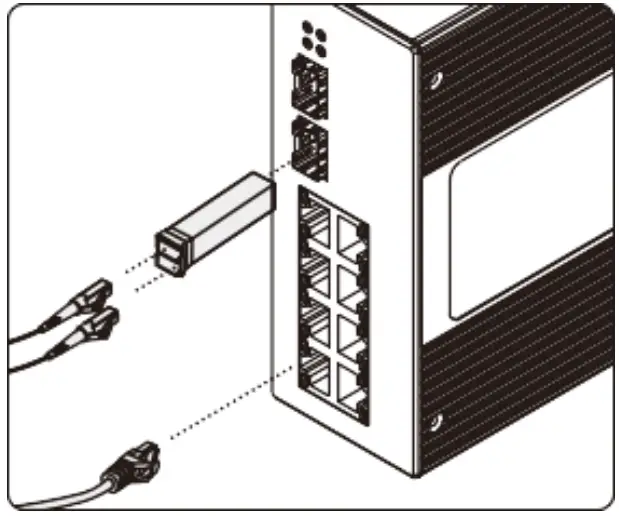
Device connection
- Network cables connection Connect the optical fiber and network cable to the port in the correct


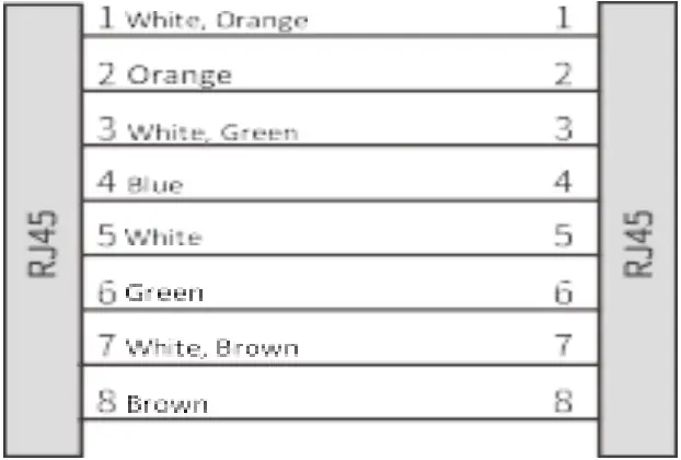
Catagory5 direct connection
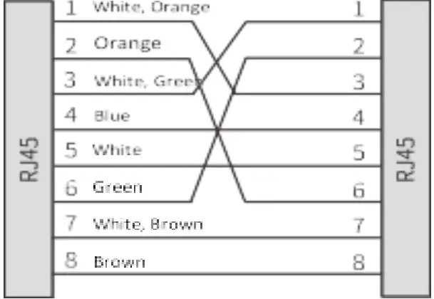
Catagory5 crossover connection
![]() Warning
Warning
- Signals were transmitted by laser through optical fiber. The laser meets the requirement of class I, no harm with normal operation. Do not look directly into the fiberport and the end of the optical fiber terminator.
- Dust plugs need to be installed when optical connectors and optical modules are not in use. Dust caps need to be installed when optical fibers are not in use.
- The bending radius of optical fiber should be greater than 20 times the diameter of the optical fiber. In general, the bending radius should be equal to or greater than 40mm.
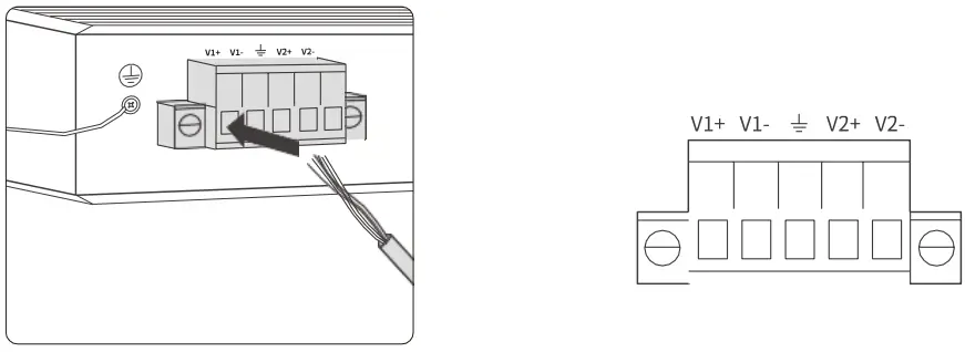
Power input
- Before connecting the power cord, make sure that the ground is connected. Do connect the power cord to the power terminal of the device according to the definition.

![]() Notes
Notes
- When using a switch, the voltage can only be input from V1+ and V1-, V1+ connects to live wire L, and V1- to neutral wire N. Do not connect from V2+, V2-; pay attention to safety and prevent electric shock.
- Power-on operation: First connect the power cord to the power terminal of the device according to the definition shown in the figure above, and then power on.
- Power-off operation: first unplug the power plug, and then remove the power cord.
Specifications
MIGE2210-2GT | MIGE2210-2GF | MIGE2210-2GF-4F | |
| Switch performance | |||
| Backplane bandwidth | 7.6G | ||
| Cache size | 1Mbit | ||
| MAC address | 8K | ||
| Interface | |||
| Gigabit SFP port | 2*1000Base-X | 2*1000Base-X | |
| SFP slot | |||
| Gigabit RJ45 port | 2* 10/100/1000MBase-TX RJ45 ports | ||
| Full duplex/half duplex self-adaptation or forced operation mode, support MDI/MDI-X self-adaptation | |||
| 100Base-FX port | 4*100Base-FX | ||
| Connector SC/FC/ST optional | |||
| 100Base-TX port | 8* 10/100Base-TX RJ45 ports | 8* 10T/100Base-TX RJ45 ports | 4* 10/100Base-TX RJ45 ports |
| Full duplex/half duplex self-adaptation or forced operation mode, support MDI/MDI-X self-adaptation | |||
| Power | |||
| Power consumption | 6.4W@24V full load | 3.8W@24V full load | 4.5W@24V full load |
| DC input | DC12~48V optional DC48V (36-72V) optional Support dual power supply redundancy, reverse connection protection | ||
| AC input | AC85~264V (frequency: 47~63Hz) or DC110~370V | ||
| Mechanical | |||
| Size | 144×54mm×110.4mm(H×W×D)(Excluding DIN rail) | ||
| Installation method | 35mm standard DIN rail installation |
| Heat dissipation form | Aluminum alloy single-rib chassis surface heat dissipation, no fan |
| IP protection | IP40 |
| Weight | About 0.67kg |
| Working environment | |
| Operating temp. | -40~+85℃ |
| Storage temp. | -40~+85℃ |
| Humidity | 5~95% (No condensation) |
| Industry standard | |
| EMC | IEC61000-4-2(ESD), Level4 IEC61000-4-5(Surge), Level4 IEC61000-4-4(EFT), Level4 IEC61000-4-3(RS), Level4 IEC61000-4-6(CS), Level4 ※The network port supports 6KV lightning protection |
Order guide
Model | Gigabit SFP | Gigabit RJ45 | 100Base-FX | 100Base-TX | Power |
MIGE2210-2GT | 0 | 2 | 0 | 8 | DC: DC12~48V, DC48V(36~72V) optional AC: AC85〜264V (Freq.:47~63Hz) or DC110〜370V |
MIGE2210-2GF | 2 | 0 | 0 | 8 | |
MIGE2210-2GF-4F | 2 | 0 | 4 | 4 |
Pledge
Thank you for purchasing Maiwe products. You will enjoy the following services when using Maiwe products.
We solemnly promises: under normal use, one month’s return, one-year free maintenance, five year warranty, and lifetime maintenance. The specific details are as follows:
- If Maiwe products have quality problems and cannot work normally, they will be refunded for one month, free maintenance for one year, warranty for five years, and maintenance for life.
- If the number of repaired products is less than 10, the repair service will be completed within 7 days (excluding transportation time), and the repair service will be completed within one month for more than 10 sets.
- Optical passive products such as optical fibers, optical cables, jumpers, flanges, and optical cable terminal boxes are guaranteed within two years, but no return service is provided.
- The accessories and power supply that come with the product are guaranteed for one year.
- When sending the product back to Maiwe for repair, it is recommended that the customer use the original packaging or the packaging with the same protective effect, otherwise the customer shall bear the risks that occur during the transportation.
- The repaired product can enjoy another 6 months warranty service.
- The product after-sales service is detailed in the purchase and sale contract, and Maiwe has the final interpretation right of this description.
![]() Statement
Statement
Due to the continuous updating and improvement of products and technologies, the contents of this manual will be updated from time to time. All the information in the manual is only used for instructions, if the content in the text does not completely match the actual product, please understand and please contact our customer service in time.
CUSTOMER SERVICE
Wuhan Maiwe Communication Co., Ltd.
Add: Building E2, No. 2 Building, Area E, No. 52 Liufang Avenue, East lake High-tech Development Zone, Wuhan, China.
Tel: 027-87170215/16
Fax: 027-87170217
Post Code: 430205
Site: www.maiwe.com


