![]()
www.hesaitech.com
Pandar40P
40-Channel Mechanical LiDAR
User Manual
HESAI Wechat
http://weixin.qq.com/r/Fzns9IXEl9jorcGX92wF
About This Manual
Using This Manual
- Make sure to read through this user manual before your first use and follow the instructions herein when you operate the product. Failure to comply with the instructions may result in product damage, property loss, personal injuries, and/or a breach of warranty.
- This user manual does not contain information on product certifications. Please check the certification marks on the product’s bottom plate and read through the corresponding certification warnings.
- If you incorporate this LiDAR product into your product(s), you are required to provide this user manual (or the means to access this user manual) to the intended users of your product(s).
Access to This Manual
To obtain the latest version:
- Visit the Download page of Hesai’s official website: https://www.hesaitech.com/en/download
- Or contact your sales representative at Hesai
- Or contact Hesai’s technical support team: [email protected]
Technical Support
If your question is not addressed in this user manual, please contact us at: [email protected]
www.hesaitech.com/zh/support
https://github.com/HesaiTechnology (Please leave your questions under the corresponding GitHub projects.)
Legends
![]() Warnings: instructions that must be followed to ensure safe and proper use of the product.
Warnings: instructions that must be followed to ensure safe and proper use of the product.![]() Notes: additional information that may be helpful.
Notes: additional information that may be helpful.
Safety Notice
Special Warnings
Laser Safety
Hot Surface
![]() CAUTION
CAUTION ![]()
Use of controls or adjustments or performance of procedures other than those specified herein may result in hazardous radiation exposure
![]()
INVISIBLE LASER RADIATON
CLASS 1 LASER PRODUCT
This product complies with IEC/EN 60825-1: 2014 and complies with FDA performance standards for laser products except for conformance with IEC 60825-1 Ed.3., as described in Laser Notice No.56, dated May 8, 2019.
Hot Surface
![]()
During or after a period of operation, do NOT touch the product’s enclosure with your skin.
Abnormalities
In any of the circumstances listed below, stop using the product immediately:
- You suspect that the product malfunctions or is damaged. For example, the product produces significant noise or is visibly vibrating.
- You or other people in the nearby environment feel discomfort.
- Any device or equipment in the nearby environment malfunctions.
Meanwhile, contact Hesai Technology or an authorized Hesai Technology service provider for more information on product disposal. Contact information can be found in the product’s user manual (refer to the About this Manual section).
Prohibition of Disassembly
Unless expressly agreed to in writing by Hesai Technology, do NOT disassemble the product.
Operating Environment
Radio Frequency Interference
Before using the product, make sure to read all the signs and notices on the product enclosure (including the bottom plate). Although the product is designed, tested, and manufactured to comply with the regulations on RF radiation (such as FCC, CE-EMC, or KCC), the radiation from the product may still influence electronic devices.
Vibration
- If significant mechanical shocks and vibration may exist in the product’s operating environment, please contact Hesai’s technical support team to obtain the shock and vibration limits of this product model. Exposure to over-the-limit shocks or vibration may damage the product.
- Make sure to package the product in shock-proof materials to avoid damage during transport.
Explosive Atmosphere and Other Air Conditions
- Do NOT use the product in any area where potentially explosive atmospheres are present, such as high concentrations of flammable chemicals, vapors, or particulates (including particles, dust, and metal powder) in the air.
- Do NOT expose the product to high concentrations of industrial chemicals, including liquefied gases that are easily vaporized (such as helium). Such exposure can damage or weaken the product’s function.
Ingress Protection
Please check the product’s user manual for its IP rating (refer to the Specifications section). Make sure to avoid any ingress beyond that rating.
Operating Temperature
Please check the product’s user manual for its operating temperature (refer to the Specifications section). Make sure not to exceed the operating temperature range.
Recommended Storage Conditions
Store the product in a dry, well ventilated place. The recommended ambient temperature is 23±5°C, and the humidity between 30% and 70%.
Light Interference
Certain precision optical instruments may be interfered by the laser light emitted from the product. Please check all the instructions of these instruments and take preventive measures if necessary. For example, when the product is temporarily not used for measurement, the protective leather cover (supplied with the product) can be used to block laser light emission.
Personnel
Recommended Operator Qualifications
The product should be operated by professionals with engineering backgrounds or experience in operating optical, electrical, and mechanical instruments. Please follow the instructions in this manual when operating the product and contact Hesai technical support if needed.
Medical Device Interference
- Some components in the product can emit electromagnetic fields. If the product operators or other people in the nearby environment wear medical devices (such as cochlear implants, heart pacemakers, and defibrillators), make sure to consult the physicians and medical device manufacturers for medical advice, such as determining whether it is safe to work near the product.
- If you suspect that the product is interfering with your medical device, stop using the product immediately.
Installation and Operation
Power Supply
- You are recommended to use only the cables and power adapters provided by Hesai Technology.
- If you are to design, configure, or select the power supply system (including cables) for the product, make sure to comply with the electrical specifications in the product’s user manual (refer to the Specifications section and the Power Supply Requirements section); for technical support, please contact Hesai Technology. Do NOT use off-spec or damaged cables or adapters.
Electrical Interface
- Before powering on the product, make sure the electrical interfaces are dry and clean. Do NOT power on the product in a humid environment.
- Please check the Interfaces section in the product’s user manual and strictly follow the instructions on plugging/unplugging the connector.
If abnormalities already exist (such as bent pins, broken cables, and loose screws), stop using the product and contact Hesai technical support. - To prevent breakdown, turn off the power source before connection and disconnection.
Eye Safety
The product is a Class 1 laser product. It satisfies the requirements of:
- IEC 60825-1:2014.
- 21 CFR 1040.10 and 1040.11 except for deviations (IEC 60825-1 Ed.3) pursuant to Laser Notice No.56, dated May 8, 2019.
Please follow the standard laser safety guidelines accordingly.
For maximum self-protection, it is strongly warned NOT to look into the transmitting laser through a magnifying product (microscope, eye loupe, magnifying glass, etc.).![]() This product does not have a power switch. It starts operating once connected to power. During operation, the entire cover lens can be regarded as the product’s laser emitting window; looking at the cover lens can be regarded as looking into transmitting laser.
This product does not have a power switch. It starts operating once connected to power. During operation, the entire cover lens can be regarded as the product’s laser emitting window; looking at the cover lens can be regarded as looking into transmitting laser.
Product Enclosure
- The product contains metal, glass, plastic, as well as sensitive electronic components. In case the product has been dropped and burnt, stop using it immediately and contact Hesai technical support.
- Do NOT squeeze or pierce the product. If the product enclosure is broken, stop using it immediately and contact Hesai technical support.
- The product contains high-speed rotating parts. To avoid potential injuries, do NOT operate the product if the enclosure is loose.
- Before operating the product, make sure it is properly and securely mounted. The mounting should prevent the product from leaving its mounting position in case of external forces (such as collisions, high winds, and stone impacts).
- If the product enclosure consists of fins or grooves, please wear gloves when handling the product. Applying too much pressure with your bare hands may cause cuts, bruises or other injuries.
Product Enclosure: Cover Lens
- To keep the product’s cover lens from fingerprints and other stains, do NOT touch the cover lens with bare hands. If the cover lens is already stained, please refer to the cleaning method in the Sensor Maintenance section of the user manual.
- To prevent scratches, do NOT touch the product’s cover lens with hard or sharp objects. If scratches already exist, stop using the product and contact Hesai technical support. Severe scratches may affect the quality of the product’s point cloud data.
Hot Surface
During operation or a time period after operation, the product’s enclosure can be hot.
- To prevent discomfort or even burns, do NOT touch the product’s enclosure with your skin.
- To prevent fires, do NOT touch the product’s enclosure with flammable materials.
Peripherals
The product may be used along with accessories and devices, such as suction cup mounts, extension cables, power supplies, network devices, GPS/PTP devices, and cleaning equipment. Please refer to all relevant specifications in the product’s user manual, or contact Hesai technical support. Using off-spec or unsuitable devices may result in product damage or even personal injuries.
Firmware and Software Upgrading
Make sure to use only the upgrade files provided by Hesai Technology. Make sure to observe all the instructions provided for that upgrade file.
Custom Firmware and Software
- Before using a custom version of firmware and software, please thoroughly understand the differences in functions and performance between this custom version and the standard version.
- Make sure to strictly follow all the instructions and safety precautions provided for that custom version. If the product does not function as anticipated, stop using the product immediately and contact Hesai technical support.
Point Cloud Data Processing
The point cloud data processing features (provided on certain product models) are configurable and are intended only to assist users in extracting information from the point cloud data. Users are in full control whether to use any of these features. Moreover, users are responsible for analyzing the product’s intended application scenarios and evaluating the risks of enabling one or more of these features in combination. The point cloud data processing features include but are not limited to: Noise Filtering, Interstitial Points Filtering, Retro Multi-Reflection Filtering, and Nonlinear Reflectivity Mapping.
Repair and Maintenance
For product repair or maintenance issues, please contact Hesai Technology or an authorized Hesai Technology service provider. Contact information can be found in the product’s user manual (refer to the About this Manual section).
Repair
Unless expressly agreed to in writing by Hesai Technology, do NOT by yourself or entrust any third party to disassemble, repair, modify, or retrofit the product. Such a breach:
- can result in product damage (including but not limited to water resistance failure), property loss, and/or personal injuries;
- shall constitute a breach of warranty.
Introduction
This manual describes the specifications, installation, and data output format of Pandar40P.
Operating Principle
Distance Measurement: Time of Flight (ToF)
- A laser diode emits a beam of ultrashort laser pulses onto the target object.
- The laser pulses are reflected after hitting the target object. The returning beam is detected by an optical sensor.
- Distance to the object can be accurately measured by calculating the time between laser emission and receipt.

d: distance
c: speed of light
t: travel time of the laser beamFigure 1.1 Distance Measurement Using Time of Flight
LiDAR Structure
40 pairs of laser emitters and receivers are attached to a motor that rotates horizontally.
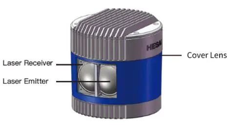 Figure 1.2 Partial Cross-Sectional Diagram Figure 1.2 Partial Cross-Sectional Diagram | 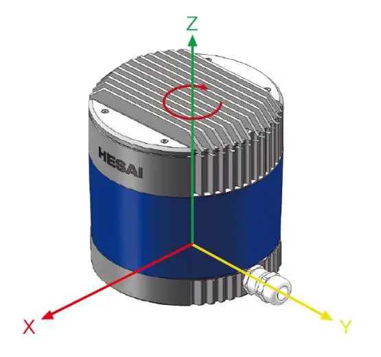 Figure 1.3 Coordinate System (Isometric View) Figure 1.3 Coordinate System (Isometric View) | 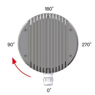 Figure 1.4 Rotation Direction (Top View) Figure 1.4 Rotation Direction (Top View) |
The LiDAR’s coordinate system is illustrated in Figure 1.3. Z-axis is the axis of rotation.
The origin is shown as a red dot in Figure 1.6 on the next page. All measurements are relative to the origin.
Each laser channel has an intrinsic horizontal angle offset. When Channel 12 passes the zero-degree position in Figure 1.4, the azimuth data in the corresponding UDP data block will be 0°.
Channel Distribution
The vertical resolution is
- 0.33° between Channel 6 and Channel 30
- 1° between Channel 5 and Channel 6, Channel 30 and Channel 38
- not evenly distributed in the remaining channels, as detailed in Appendix I

Each channel has an intrinsic angle offset, both horizontally and vertically. The offsetted angles are recorded in this LiDAR unit’s angle correction file, which is provided when shipping the unit.
In case you need to obtain the file again:
- Send this PTC command PTC_COMMAND_GET_LIDAR_CALIBRATION, as described in Hesai TCP API Protocol (Chapter 5).
- Or export the file using Pandar View, see the Pandar View user manual.
- Or contact a sales representative or technical support engineer from Hesai.
Specifications
SENSOR
| Scanning Method | Mechanical Rotation |
| Channel | 40 |
| Range Capability | 0.3 to 200 m (at 10% reflectivity) |
| Range Accuracy ① | ±5 cm (0.3 to 1 m) ±2 cm (1 to 200 m) |
| FOV (Horizontal) | 360° |
| Resolution (Horizontal) | 0.2° (10 Hz), 0.4° (20 Hz) |
| FOV (Vertical) | 40° (-25° to +15°) |
| Resolution (Vertical) | 0.33° (-6° to +2°) 1° (+2° to +3°, -14° to -6°) 2° (+3° to +5°) 3° (+5° to +11°) 4° (+11° to +15°) 5° (-19° to -14°) 6° (-25° to -19°) |
| Frame Rate | 10 Hz, 20 Hz |
| Returns | Single Return (Last, Strongest) Dual Return (Last and Strongest) |
MECHANICAL/ELECTRICAL/OPERATIONAL
| Wavelength | 905 nm |
| Laser Class | Class 1 Eye Safe |
| Ingress Protection | IP6K7 |
| Dimensions | Height: 116.7 mm Top/Bottom: Φ118.0 / 116.0 mm |
| Rated Voltage Range | DC 9 to 48 V |
| Power Consumption ② | 18 W (typical) |
| Operating Temperature | -20℃ to 65℃ |
| Storage Temperature | -40℃ to 85℃ |
| Weight | 1.52 kg |
DATA I/O
| Data Transmission | UDP/IP Ethernet (100 Mbps) |
| Measurements | Distance, Azimuth Angle, Intensity |
| Data Points Generated | Single Return: 720,000 points/sec Dual Return: 1,440,000 points/sec |
| Point Cloud Data Rate | Single Return: 18.78 Mbps Dual Return: 37.56 Mbps |
| Clock Source | GPS / PTP |
| PTP Clock Accuracy | ≤1 μs |
| PTP Clock Drift ③ | ≤1 μs/s |
![]() Specifications are subject to change. Please refer to the latest version.
Specifications are subject to change. Please refer to the latest version.
- Range accuracy
• Defined as the average range error across all channels.
• May vary with range, temperature, and target reflectivity. - Power consumption
• Not including accessories such as the connection box. - PTP Clock Drift
• Defined as the drift at a constant temperature after the LiDAR (slave clock) loses connection to the PTP master.
Setup
Mechanical Installation
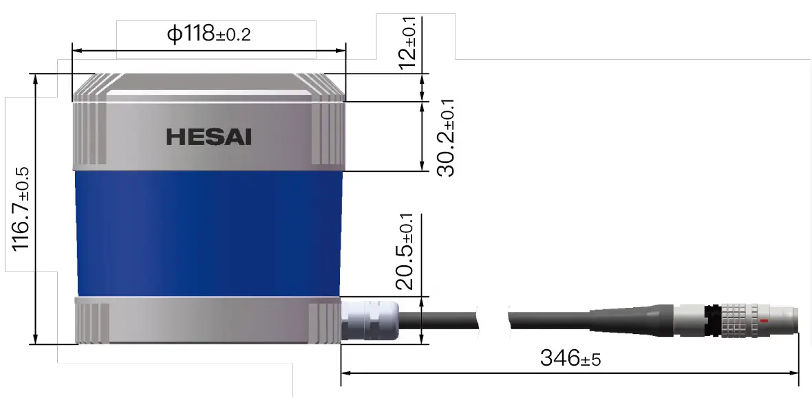
Figure 2.1 Front View (Unit: mm)
Figure 2.2 Bottom View (Unit: mm)
Quick Installation
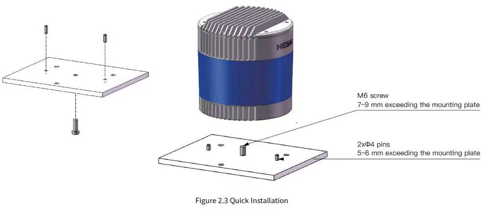
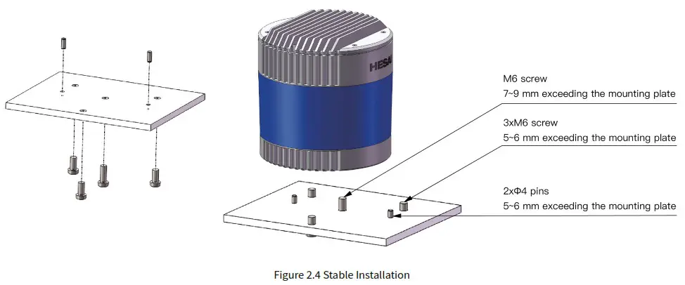
Stable Installation
Interfaces
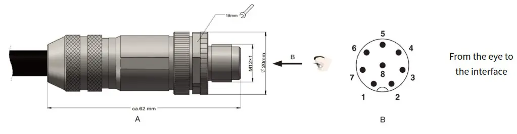
Lemo Contact is the default communication connector. (Another option is the Phoenix Contact, detailed in the appendix)
Lemo part number: FGG.2T.316.CLAC75Z (male plug, on the LiDAR)
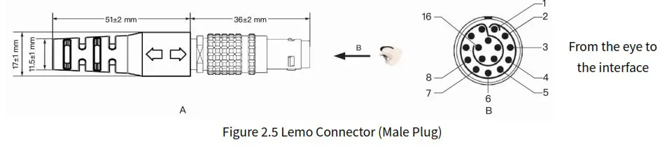
| Pin # | Signal | Color | Voltage |
| 1 ~ 4 | – | – | – |
| 5 | Ethernet RX- | BLUE | -1 to 1 V |
| 6 | Ethernet RX+ | BLUE/WHITE | -1 to 1 V |
| 7 | Ethernet TX- | ORANGE | -1 to 1 V |
| 8 | Ethernet TX+ | ORANGE/WHITE | -1 to 1 V |
| 9 | GPS Serial Data | WHITE | -13 to +13 V |
| 10 | GPS PPS | YELLOW | TTL 3.3/5 V |
| 11 | Power | RED | 9 to 48 V |
| 12 | Power | GRAY | 9 to 48 V |
| 13 | Ground (Return) | BLACK | 0 V |
| 14 | Ground (Return) | GRAY/WHITE | 0 V |
| 15 | – | PURPLE | – |
| 16 | – | PURPLE/WHITE | – |
![]() For the GPS PPS signal, pulse width is recommended to be over 1 ms, and the cycle is 1 s (rising edge to rising edge)
For the GPS PPS signal, pulse width is recommended to be over 1 ms, and the cycle is 1 s (rising edge to rising edge)![]() Before connecting or disconnecting an external GPS signal (either using the cable’s GPS wire or via the connection box’s GPS port), make sure the LiDAR is powered off. If the LiDAR has to stay powered on, make sure to:
Before connecting or disconnecting an external GPS signal (either using the cable’s GPS wire or via the connection box’s GPS port), make sure the LiDAR is powered off. If the LiDAR has to stay powered on, make sure to:
- ground yourself in advance
- avoid touching the GPS wire or GPS port with bare hands
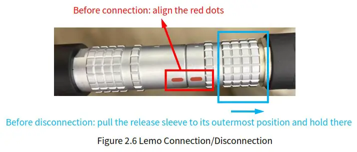
Connector Use
| Connection | Disconnection |
| • Turn off the power source • Align the red dots on the connector shells • Push the plug straight into the socket | • Turn off the power source • Pull the release sleeve on the male connector to its outermost position and hold there • Pull the plug from the socket |
![]() Warnings
Warnings
- DO NOT attempt to force open a connection by pulling on the cables or the shells, or by twisting the connectors in any way. Doing so can loosen the connectors’ shells, or even damage the contacts.
- In case a connector’s shell is accidentally pulled off, stop using the connector and contact Hesai technical support.
- DO NOT attempt to assemble the connector’s shell and cable collet; DO NOT connect a connector without its shell. Doing so may damage the LiDAR’s circuits.
Cables
OD (outside diameter) = 7.50±0.30 mm
Minimum bend radius: 7.5 * OD
![]() To avoid damaging the cable, do not bend the cable at the cable gland.
To avoid damaging the cable, do not bend the cable at the cable gland.
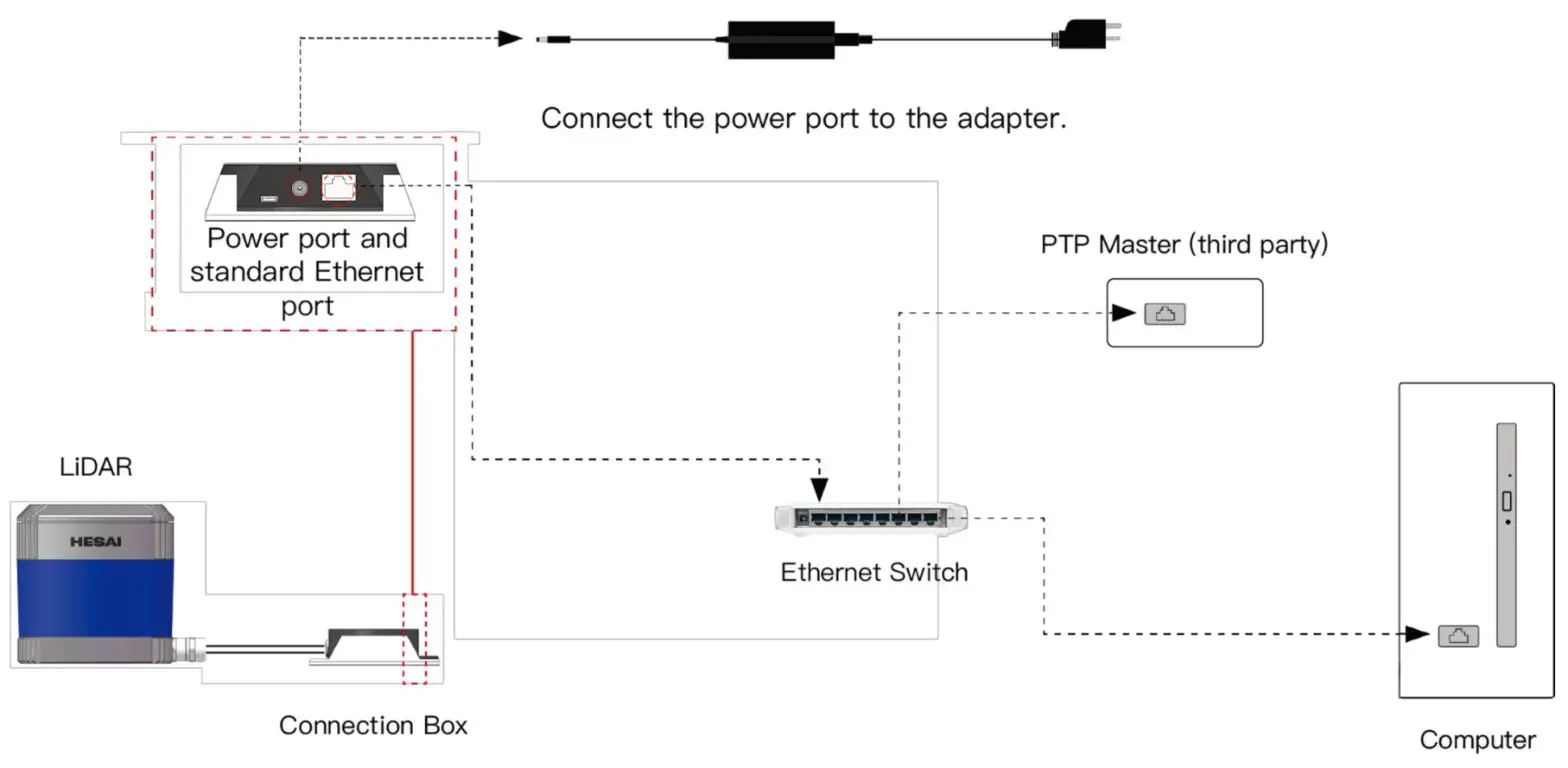
Connection Box (Optional)
Users may connect the LiDAR directly or using the connection box.
Lemo part number: PHG.2T.316.CLLC75Z (female socket, on the connection box)
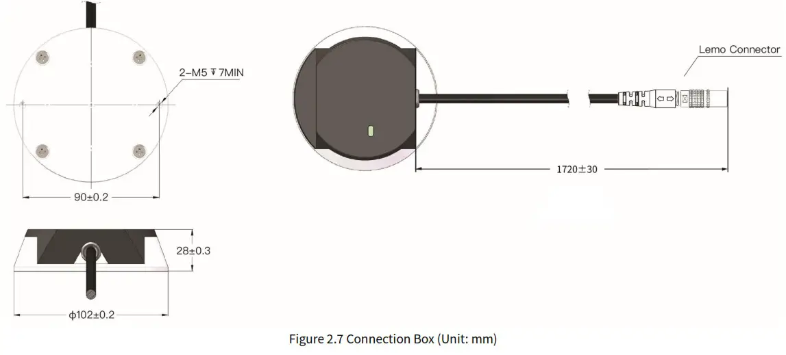
Connection Box Interfaces
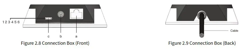
| Port # | Port Name | Description |
| a | Standard Ethernet Port | RJ45, 100 Mbps Ethernet |
| b | Power Port | Use DC-005 DC power adapter External power supply: 9 V to 48 V, at least 18 W |
| c | GPS Port | Connector part number: JST SM06B-SRSS-TB Recommended connector for the external GPS module: JST SHR-06V-S-B Voltage standard: RS232 Baud rate: 9600 bps |
The GPS port pin numbers are 1 to 6 from left to right, defined as follows:
| Pin # | Direction | Pin Description | Requirements |
| 1 | Input | PPS (pulse-per-second) signal for synchronization | TTL level 3.3/5 V Recommended pulse width: ≥1 ms Cycle: 1 s (from rising edge to rising edge) |
| 2 | Output | Power for the external GPS module | 5 V |
| 3 | Output | Ground for the external GPS module | – |
| 4 | Input | Receiving serial data from the external GPS module | RS232 level |
| 5 | Output | Ground for the external GPS module | – |
| 6 | – | Reserved | – |
Connection
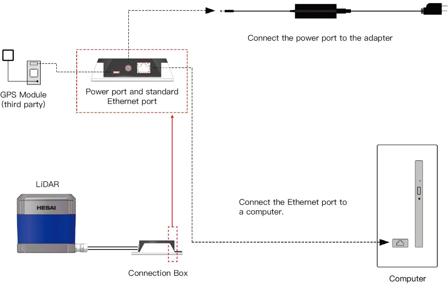 Figure 2.10 Connection Box – Connection
![]() Refer to Appendix III (PTP Protocol) when PTP protocol is used.
Refer to Appendix III (PTP Protocol) when PTP protocol is used.
Get Ready to Use
Before operating the LiDAR, strip away the protective cover outside the cover lens.
The LiDAR does not have a power switch. It starts operating once connected to power and the Ethernet.
To receive data on your PC, set the PC’s IP address to 192.168.1.100 and subnet mask to 255.255.255.0
| For Ubuntu: | For Windows: |
| Input this ifconfig command in the terminal: ~$ sudo ifconfig enp0s20f0u2 192.168.1.100 (replace enp0s20f0u2 with the local Ethernet port name) | Open the Network Sharing Center, click on “Ethernet” In the “Ethernet Status” box, click on “Properties” Double-click on “Internet Protocol Version 4 (TCP/IPv4)” Configure the IP address to 192.168.1.100 and subnet mask to 255.255.255.0 |
To record and display point cloud data, see PandarView User Manual.
To set parameters, check device info, or upgrade firmware/software, see Chapter 4 (Web Control)
To obtain the SDKs (Software Development Kits) for your product model,
- please find the download link at: www.hesaitech.com/en/download (Product Documentation select product model)
- or visit Hesai’s official GitHub page: https://github.com/HesaiTechnology
Data Structure
The LiDAR outputs Point Cloud Data Packets and GPS Data Packets using 100 Mbps Ethernet UDP/IP.
Unless otherwise specified, all the multi-byte fields are unsigned values in little endian format.
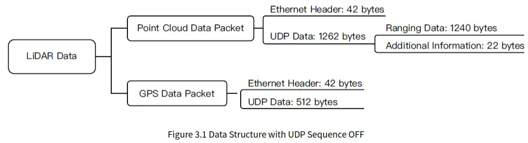 UDP sequence is OFF by default . When UDP sequence is ON, the Additional Information in the UDP data changes from 22 bytes to 26 bytes.
Point Cloud Data Packet
Ethernet Header
Each LiDAR has a unique MAC address. The source IP is 192.168.1.201 by default, and the destination IP is 255.255.255.255 (broadcast).
Point Cloud Ethernet Header: 42 bytes
| Field | Bytes | Description |
| Ethernet II MAC | 12 | Destination: broadcast (OxFF: OxFF: OxFF: OxFF: OxFF: OxFF) Source: (xx:xx:xx:xx:xx:xx) |
| Ethernet Data Packet Type | 2 | 0x08, Ox00 |
| Internet Protocol | 20 | Shown in the figure below |
| UDP Port Number | 4 | UDP source port (0x2710, representing 10000) Destination port (0x0940, representing 2368) |
| UDP Length | 2 | 0x04F6 when UDP sequence is OFF, representing 1270 bytes (8 bytes more than the size of the Point Cloud UDP Data, shown in Figure 3.1) Ox04FA when UDP sequence is ON, representing 1274 bytes |
| UDP Checksum | 2 | Shown in the figure below |
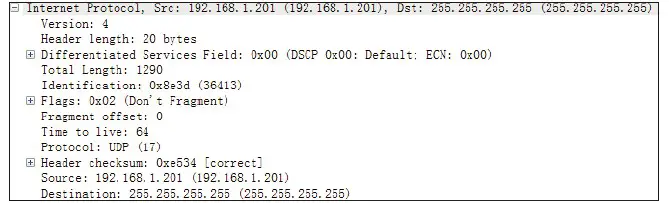
Figure 3.2 Point Cloud Ethernet Header – Internet Protocol
UDP Data
Ranging Data: 1240 bytes (10 blocks)
| Block 1 | Block 2 | Block 3 | … | Block 10 |
| 0xFFEE | 0xFFEE | 0xFFEE | … | 0xFFEE |
| Azimuth 1 | Azimuth 2 | Azimuth 3 | … | Azimuth 10 |
| Channel 1 | Channel 1 | Channel 1 | … | Channel 1 |
| Channel 2 | Channel 2 | Channel 2 | … | Channel 2 |
| … | … | … | … | … |
| Channel 40 | Channel 40 | Channel 40 | … | Channel 40 |
Block size = 2 + size of Azimuth + 40* size of Channel X
| Each block in the Ranging Data: 124 bytes | |||
| Field | Bytes | Description | |
| OxFFEE | 2 | Header, meaningless, OxFF first | |
| Azimuth | 2 | Current reference angle of the rotor Unit: 0.01° | |
| Channel X | 3 | 2-byte Distance | Distance Value = Distance ‘ 4 mm |
| 1-byte Reflectivity | Range: 0 to 255 The mapping from this field to target reflectivity can be selected in Section 4.2 (Web Control -Settings) | ||
In Dual Return mode, the measurements from each round of firing are stored in two adjacent blocks:
- The odd number block is the last return, and the even number block is the strongest return
- If the last and strongest returns coincide, the second strongest return will be placed in the even number block
- The Azimuth changes every two blocks
Additional Information: 22/26 bytes when UDP sequence is OFF/ON
| Field | Bytes | Description | |
| Reserved | 5 | – | |
| High Temperature Shutdown Flag | 1 | Ox01 for high temperature; Ox00 for normal operation •When high temperature is detected, the shutdown flag will be set to Ox01, and the system will shut down after 60 s. The flag remains Ox01 during the 60 s and the shutdown period •When the system is no longer in high temperature status, the shutdown flag will be reset to Ox00 and the system will automatically return to normal operation | |
| Reserved | 2 | – | |
| Motor Speed | 2 | Unit: RPM | |
| Timestamp | 4 | The “vs time” part of the absolute time of this data packet (defined in Appendix II), in units of 1 is Range: 0 to 1000000 vs (1 s) | |
| Return Mode | 1 | 0x37 for Strongest Return mode 0x38 for Last Return mode 0x39 for Dual Return mode | |
| Factory Information | 1 | 0x42 (or Ox43) | |
| Date & Time | 6 | The absolute UTC time of this data packet, accurate to the second. | |
| Each Byte | Range (Decimal) | ||
| Year (current year minus 2000) | Positive integers | ||
| Month | 1 to 12 | ||
| Day | 1 to 31 | ||
| Hour | 0 to 23 | ||
| Minute | 0 to 59 | ||
| Second | 0 to 59 | ||
| UDP Sequence | 4 | Added only when UDP sequence is ON Label the sequence number of Point Cloud UDP packets 0 to 0xFF FF FF FF | |
Point Cloud Data Analysis
The analysis of point cloud UDP data consists of three steps.
Analyze the vertical angle, horizontal angle, and distance of a data point
Take Channel 5 in Block 3 as an example:
- Vertical angle of Channel 5 is 3.00°, according to Appendix I (Channel Distribution)
 The accurate vertical angle is recorded in this LiDAR’s unit’s angle correction file, see Section 1.3 (Channel Distribution).
• 0° represents the horizontal direction
• Define upward as positive
• The Channel # counts from 1 from the uppermost - Horizontal angle = current reference angle of the rotor + horizontal angle offset + firing time angular offset
• Current reference angle of the rotor is the Azimuth field of Block 2
• Horizontal angle offset: -1.042° for Channel 5, according to Appendix I (Channel Distribution) The accurate horizontal angle offset is recorded in this LiDAR’s unit’s angle correction file, see Section 1.3 (Channel Distribution).Firing time angular offset = Firing Time Offset of Channel 5 (see Appendix II) * Spin Rate of the Motor (see Section 4.1 Web Control – Home)
• Define clockwise in the top view as positive - Actual distance in real world millimeters = distance measurement * Distance Unit (4 mm)
Distance measurement is the Distance field of Channel 5 in Block 3
(Continued on the next page)
Draw the data point in a spherical or rectangular coordinate system
Obtain the real-time point cloud data by analyzing and drawing every data point in a frame
GPS Data Packet
GPS Data Packets are triggered every second.
Before NMEA messages are available from the external GPS module
Each rising edge of the LiDAR’s internal 1 Hz signal triggers a GPS Data Packet. The time and date in the GPS Data Packets are unreal, starting from the UTC time 00 01 01 00 00 00 (year, month, day, hour, minute, second) and increasing with the internal 1 Hz signal.
Once the LiDAR receives the PPS (pulse-per-second) signal and NMEA messages
The internal 1 Hz signal will be locked to the PPS. Each rising edge still triggers a GPS Data Packet. Meanwhile, the LiDAR will extract the actual date and time from NMEA messages ($GPRMC or $GPGGA), and stamp them into both Point Cloud Data Packets and GPS Data Packets.
- Point Cloud Data Packets: 6-byte Date & Time (year, month, day, hour, minute, second)
- GPS Data Packets: 6-byte Date (year, month, day) and 6-byte Time (second, minute, hour)
The GPS module sends first the PPS signal and then the NMEA message. At the rising edge of the PPS pulse, the corresponding NMEA message is not yet available. Therefore, the LiDAR extracts date and time from the previous NMEA message and automatically adds 1 full second.
When GPS signal is lost
The LiDAR will still trigger GPS Data Packets by the rising edge of the internal 1 Hz signal. However, the GPS time in the packets will be counted by the internal 1 Hz signal and will drift from the actual GPS time.
Ethernet Header
The source IP is 192.168.1.201 by default. The destination IP address is 255.255.255.255 and in broadcast form.
| GPS Ethernet Header:42 bytes | ||
| Field | Bytes | Description |
| Ethernet II MAC | 12 | Destination: broadcast (OxFF: OxFF: OxFF: OxFF: OxFF: OxFF) Source: (xx:xx:xx:xx:xx:xx) |
| Ethernet Data Packet Type | 2 | Ox08, Ox00 |
| Internet Protocol | 20 | Shown in the figure below |
| UDP Port Number | 4 | UDP source port (0x2710, represents 10000) Destination port (0x277E, represents 10110) |
| UDP Length | 2 | 0x208, representing 520 bytes (8 bytes more than the size of the GPS UDP Data, shown in Figure 3.1) |
| UDP Checksum | 2 | – |
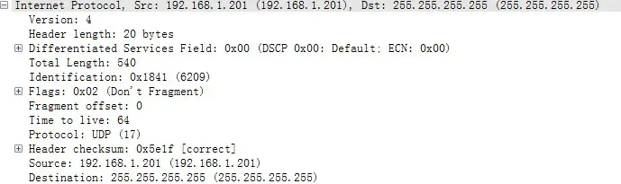
Figure 3.3 GPS Ethernet Header – Internet Protocol
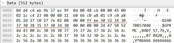
UDP Data
| GPS UDP data: 512 bytes | ||||
| Field | Bytes | Description | ||
| GPS Time Data | 18 | Header | 2 bytes | OxFFEE (OxFF first) |
| Date | 6 bytes | Year, month, and day (2 bytes each, lower byte first) in ASCII | ||
| Time | 6 bytes | Second, minute, and hour (2 bytes each, lower byte first) in ASCII | ||
| Reserved | 4 bytes | – | ||
| GPRMC/GPGGA Data | g | NMEA sentence that contains date and time ASCII code, valid till 2 bytes after the asterisk (•) The LiDAR can receive either GPRMC or GPGGA, see Chapter 4 (Web Control – Settings) | ||
| Reserved | 404 | 404 bytes of OxDF | ||
| GPS Positioning Status | 1 | ASCII code, obtained from $GPRMC or $GPGGA When $GPRMC is selected: When $GPGGA is selected: A (hex = 41) for Active 0 = invalid V (hex = 56) for Void 1= GPS fix (SPS) NUL (hex = 0) for GPS being unlocked 2 = DGPS fix 3 = PPS fix 6 = estimated (dead reckoning) | ||
| PPS Lock Flag | 1 | 1- locked 0 – unlocked | ||
| Reserved | 4 | – | ||
GPRMC Data Format
$GPRMC, <01>, <02>, <03>, <04>, <05>, <06>, <07>, <08>, <09>, <10>, <11>, <12>*hh
| Field # | Field | Description |
| <01> | UTC Time | Hour, minute, and second Typically in hhmmss (hour, minute, second) format |
| <02> | Location Status | A (hex = 41) for Valid Position V (hex = 56) for Invalid Position NUL (hex = 0) for GPS being unlocked |
| <09> | UTC Date | Date information Typically in ddmmyy (day, month, year) format |
| … |
The LiDAR’s GPS data interface is compatible with a variety of GPRMC formats, as long as:
<01> is the hour, minute, and second information
<09> is the date information.
For example, the following two formats are both acceptable:
$GPRMC,072242,A,3027.3680,N,11423.6975,E,000.0,316.7,160617,004.1,W*67 $GPRMC,065829.00,A,3121.86377,N,12114.68322,E,0.027,,160617,,,A*74
GPGGA Data Format
$GPGGA, <01>, <02>, <03>, <04>, <05>, <06>, <07>, <08>, <09>, <10>, <11>, <12>*hh
| Field # | Field | Description |
| <01> | UTC Time | Hour, minute, and second Typically in hhmmss (hour, minute, second) format |
| … | ||
| <06> | GPS Fix Quality | 0 = invalid 1= GPS fix (SPS) 2 = DGPS fix 3 = PPS fix 6 = estimated (dead reckoning) |
| … |
The LiDAR’s GPS data interface is compatible with a variety of GPGGA formats, as long as:
<01> is the hour, minute, and second information
For example, the following two formats are both acceptable:
$GPGGA,123519,4807.038,N,01131.000,E,1,08,0.9,545.4,M,46.9,M,,*47 $GPGGA,134658.00,5106.9792,N,11402.3003,W,2,09,1.0,1048.47,M,-6.27,M,08,AAAA*60
GPS Data Analysis
Date
| Field | Data (ASCII Code) | Characters | Meaning |
| Year | 0x30 0x32 | 20 | |
| Month | 0x34 0x30 | 4 | |
| Day | 0x37 0x30 | ‘7’, ‘0’ | 7 |
Data
| Field | Data (ASCII Code) | Characters | Meaning |
| Second | 0x38 0x35 | 58 | |
| Minute | 0x37 0x30 | ‘7’, ‘0’ | 7 |
| Hour | Ox34 0x30 | 4 |
μsTime
4 bytes, in units of s, using the same clock source as the GPS Timestamp in Point Cloud Data Packets Reset to 0 at the rising edge of each PPS signal
Web Control
Web control is used for setting parameters, checking device info, and upgrading.
To access web control
- Connect the LiDAR to your PC using an Ethernet cable
- Set the IP address according to Section 2.4 (Get Ready to Use)
- Enter this URL into your web browser: 192.168.1.201 Google Chrome and Mozilla Firefox are recommended.
Home
![]() This screenshot may not display the most current version numbers. See Section 4.5 (Upgrade).
This screenshot may not display the most current version numbers. See Section 4.5 (Upgrade).
Spin Rate of the motor (revs per minute) = frame rate (Hz) * 60
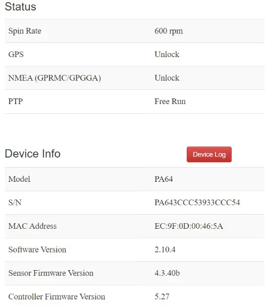
GPS (PPS) Status
| Lock | LiDAR’s internal clock is in sync with the GPS |
| Unlock | Not in sync |
NMEA (GPRMC/GPGGA) Status
| Lock | After receiving a valid NMEA message |
| Unlock | Not receiving a valid NMEA message in 2 seconds |
PTP Status
| Free Run | No PTP master is selected |
| Tracking | Slave is trying to sync with the selected PTP Master, but the absolute offset is over 1 μs |
| Locked | Absolute offset between Slave and Master is < 1 μs |
| Frozen (Holdover) | LiDAR has lost connection to the PTP master and is attempting to recover it. Meanwhile, LiDAR starts drifting from the previous clock; when drifting out of specifications, it goes back to the Free Run mode. |
Device Log
Click to download a .JSON file containing the LiDAR’s status, device info, all configurable parameters, and upgrade log.
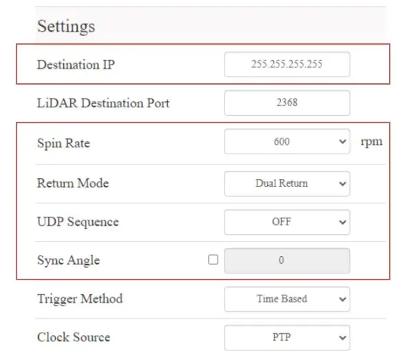
Settings
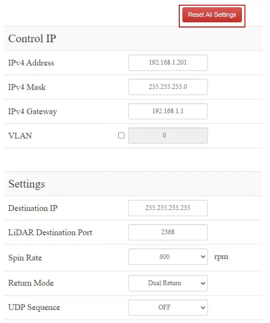
In the Settings page
- Standby Mode: effective immediately
- All other settings: effective after clicking the “Save” button at the bottom
- Reset All Settings By clicking the “Reset All Settings” button on the top-right corner, all configurable parameters on web control will be reset to factory defaults.
The default values are shown in the screenshots in
• Section 4.2 (Settings)
• Section 4.3.1 (Azimuth FOV – for All Channels) - Control IP
VLAN Tagging (VLAN ID) 1 to 4094 To enable VLAN tagging:
• Make sure the receiving host also supports VLAN.
• Check the checkbox and input the LiDAR’s VLAN ID (same as the receiving host’s VLAN ID). Notes
• Once configured, the VLAN ID does not change during firmware upgrades. Warnings
If the LiDAR’s VLAN ID differs from the receiving host’s, users will lose access to web control. To
minimize such risks, the VLAN ID is zero (invalid value) by default.
• When checking the checkbox, users will be alerted to input a valid VLAN ID.
• When unchecking the checkbox, the VLAN ID will default to zero.
- Destination IP
Range: except for 0.0.0.0, 127.0.0.1, and the LiDAR’s IPMode Destination IP Broadcast (default) 255.255.255.255 Multicast User-defined Unicast Same as the PC’s IP address - LiDAR Functions
Spin Rate 600 rpm / 1200 rpm Return Mode Last / Strongest / Dual Return UDP Sequence. OFF / ON #1 / ON #2 Point Cloud UDP packets can be labeled with a sequence number, see Section 3.1.
ON #1: UDP sequence increments only within the user-specified azimuth FOV in Section 4.3.
ON #2: Increments at all times.Sync Angle 0-360 degrees By default, the LiDAR’s 0° position (see Section 1.2) is not in sync with GPS PPS or the whole second of the PTP clock.
If syncing is needed, check the checkbox and input a sync angle.
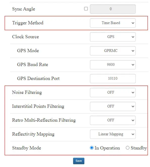
Trigger Method Angle-Based / Time-Based Angle-based: lasers fire every 0.2° at 10 Hz or 0.4° at 20 Hz.
Time-based: lasers fire every 55.56 us.Noise Filtering Mitigation of noise points Interstitial Points Filtering Interstitial point: when a beam partially hits on a front target’s edge and further hits on a rear target, the return signal can result in a false point located between both targets. Such points can be mitigated. Retro Multi- Reflection Filtering To mitigate the false positive points at twice the distance of a retroflector. Reflectivity Mapping Linear/ Nonlinear Mapping Linear the 1-byte reflectivity in Point Cloud Data Packets linearly represents target reflectivity (0 to 255%).
Nonlinear increases the contrast in low-reflectivity region, see the appendix.Standby Mode In Operation / Standby In Standby mode, the motor stops running and lasers stop firing. 
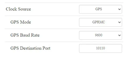
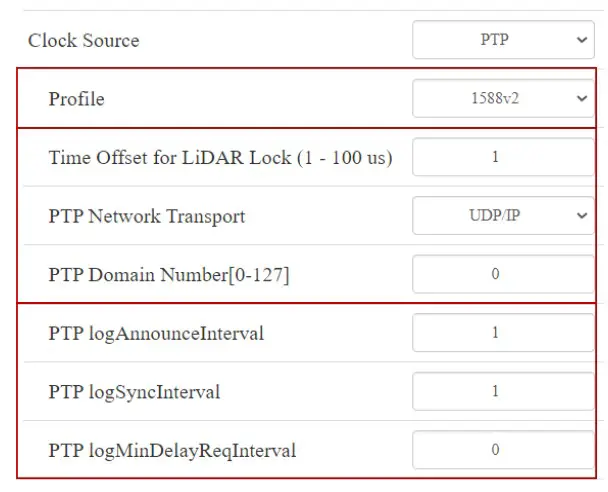
- Clock Source and PTP Parameters
Clock Source GPS / PTP In PTP mode, LiDARs do not output GPS
Data Packets (see Appendix III PTP Protocol).• When GPS is selected as the clock source:
GPS Mode GPRMC / GPGGA Format of the NMEA data received from
the external GPS module, see Section
3.2.2 (GPS UDP Data).GPS Baud Rate 9600/19200/38400/115200 GPS Destination Port 10110 (default) Port used for sending GPS Data packets  • When PTP is selected as the clock source:
Profile 1588v2 / 802.1AS / 802.1AS Automotive IEEE timing and synchronization standard Time Offset for LiDAR Lock 1 to 100 vs (integer) Specify the upper limit of the absolute offset between Slave and Master when the LiDAR is in PTP Locked status. See Section 4.1 (Home) PTP Network Transport UDP/IP or L2 UDP/IP: available only for 1588v2 profile L2: available for all profiles PTP Domain Number Integer from 0 to 127 Domain attribute of the local clock • When using the 1588v2 profile:
PTP logAnnounceln- terval -2 to 3 log seconds Time interval between Announce messages Default: 1 log second (2 seconds) PTP logSyncInterva I -7 to 3 log seconds Time interval between Sync messages Default: 1 log second (2 seconds) PTP logMinDelayReq- Interval -7 to 3 log seconds Minimum permitted mean time between Delay_Req messages
Default: 0 log second (1 second) • When using the 802.1AS or 802.1AS Automotive profile:
Switch Type TSN / Non-TSN TSN (Time Sensitive Network): Peer-toPeer delay mechanism
Non-TSN: End-to-End delay mechanism
 • When PTP is selected as the clock source:
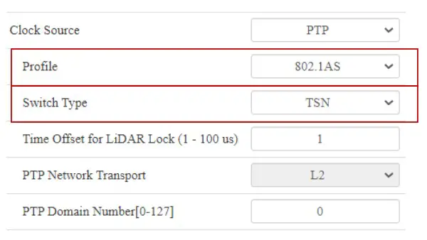 • When using the 802.1AS or 802.1AS Automotive profile:
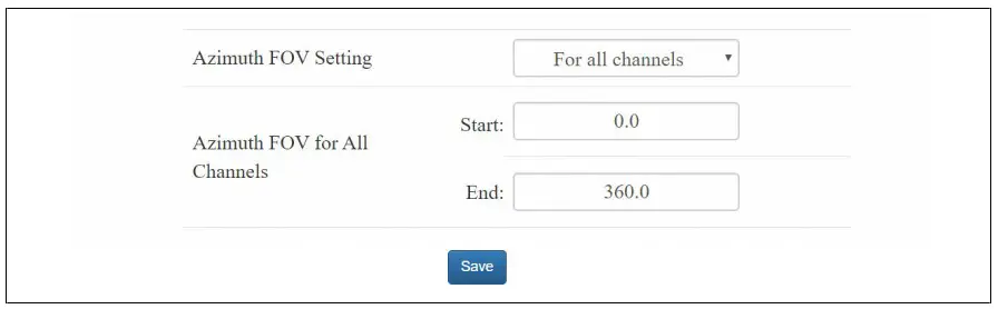
Azimuth FOV
For Azimuth FOV Setting, users can select one of the three modes.
 For all channels
A continuous angle range, specified by a Start Angle and an End Angle, will be applied to all channels.
The LiDAR outputs valid data only within the specified range.
 For each channel
Users can configure one continuous angle range for each channel.
Each channel outputs valid data only within its specified range.
The “Status” button for each channel is gray by default, indicating that the angle range is [0°, 360°].
To activate the angle range configuration for each channel, click the corresponding button to make it green.
Click the “Enable/Disable All” button to activate/deactivate the angle range configuration for all channels.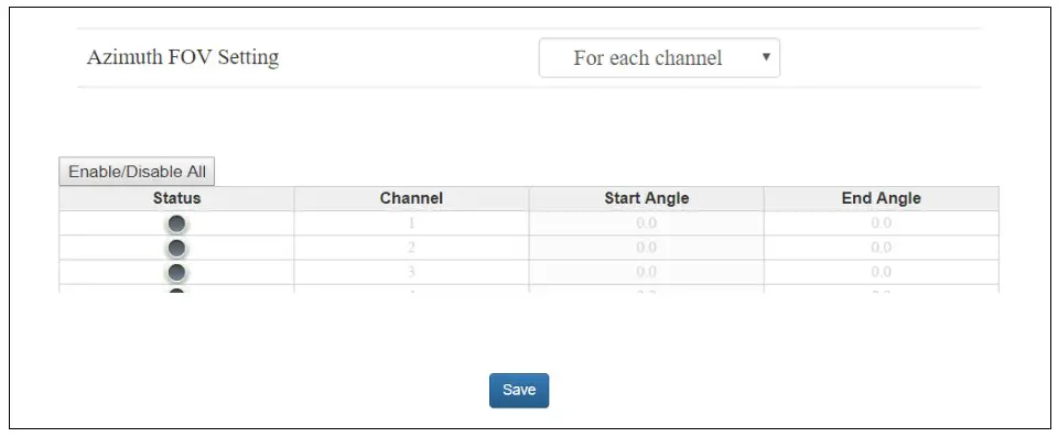
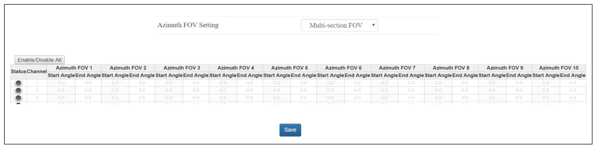
Multi-section FOV
Users can configure up to ten continuous angle ranges (i.e. sections) for each channel.
Each channel outputs valid data only within its specified ranges.
The “Status” button for each channel is gray by default, indicating that the angle range is [0°, 360°].
To activate the angle range configuration for each channel, click the corresponding button to make it green.
Click the “Enable/Disable All” button to activate/deactivate the angle range configuration for all channels.
Note
- Click “Save” to apply your settings.
- The angles in degrees are accurate to the first decimal place.
- If the Start Angle is larger than the End Angle, then the actual azimuth FOV is the union of [Start Angle, 360°] and [0°, End Angle].
For instance, when the angle range is set to be [270°, 90°], the actual azimuth FOV is [270°, 360°][0°, 90°].
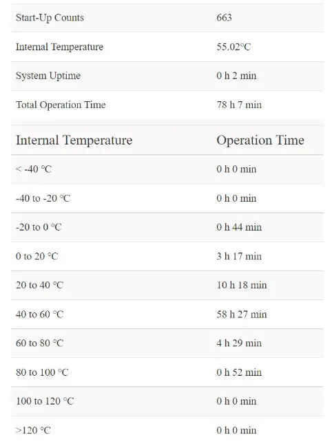
Operation Statistics
The LiDAR’s operation time in aggregate and in different temperature ranges are listed, as well as the internal temperature.
Upgrade
The software and firmware versions described in this manual are shown in the picture below. During the upgrade, it is recommended to place a protective leather cover (supplied with the LiDAR) or other opaque material over the LiDAR’s cover lens. Click the “Upload” button, select an upgrade file (provided by Hesai), and confirm your choice in the pop-up window.
When the upgrade is complete, the LiDAR will automatically reboot, and the past versions will be logged in the Upgrade Log.
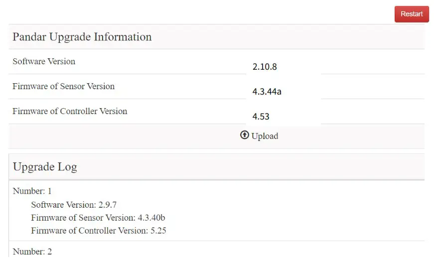
A software reboot is triggered by clicking the “Restart” button on the top right corner.
Afterwards, the start-up counts in the Operation Statistics page increments by 1.
Software and Controller Firmware
When upgrading, power supply must remain on.
Sensor Firmware
When upgrading, an interruption in the power supply can result in upgrade failure. That is, the Sensor Firmware Version on the Upgrade page becomes “XXXXX” after reboot.
Solution: upgrade Sensor Firmware again, until the Upgrade page displays the correct version number after reboot.
Software upgrade
If the current version is earlier than 2.9.1, please first upgrade to 2.9.1, and then upgrade to higher versions.
Software downgrade
If the current version is between 2.9.6 and 2.10.4, and the system needs to downgrade to a version earlier than 2.7.x, please reset all settings (click the “Reset All Settings” button on the top-right corner of the Settings page) before performing the downgrade.
Communication Protocol
To receive Hesai LiDAR’s PTC (Pandar TCP Commands) and HTTP API Protocols, please contact Hesai technical support.
Sensor Maintenance
Cleaning
Stains on the product’s cover lens, such as dirt, fingerprints, and oil, can negatively affect point cloud data quality. Please perform the following steps to remove the stains.
![]() Warnings
Warnings
- Turn OFF the power source before cleaning.
- To avoid damaging the optical coating, do NOT apply pressure when wiping the cover lens.
![]() Notes
Notes
- Only clean the stained area of the cover lens.
- Check before using a lint-free wipe. If the wipe is stained, use another.
- Thoroughly wash your hands or wear a pair of powder-free PVC gloves.
- To remove dust, blow dry air onto the cover lens, or use a piece of lint-free wipe to lightly brush across the dusty area. To remove persistent stains, move on to the next step.
- Spray the cover lens with warm, neutral solvent using a spray bottle.
Solvent type 99% isopropyl alcohol (IPA) or 99% ethanol (absolute alcohol) or distilled water When using IPA or alcohol, please ensure adequate ventilation and keep away from fire.Solvent temperature 20 to 25℃ - When the stains have loosened, dip a piece of lint-free wipe into the solvent made in Step 3, and gently wipe the cover lens back and forth along its curved surface.
- Should another cleaning agent be applied to remove certain stains, repeat Steps 3 and 4.
- Spray the cover lens with clean water, and gently wipe off the remaining liquid with another piece of lint-free wipe.
Troubleshooting
In case the following procedures cannot solve the problem, please contact Hesai technical support.
| Symptoms | Points to Check |
| Indicator light is off on the connection box | Verify that • power adapter is properly connected and in good condition • connection box is intact • input voltage and current satisfy the requirements in Section 2.3 (Connection Box) Power on again to check if the symptom persists. |
| Motor is not running | Verify that • power adapter is properly connected and in good condition • if a connection box is used, the connection box is intact • input voltage and current satisfy the requirements in Section 1.4 (Specifications) and 2.3 (Connection Box) • web control can be accessed (see “cannot open web control” on the next page) Power on again to check if the symptom persists. |
| Motor is running but no output data is received, neither on Wireshark nor on Pa ndarView | Verify that • Ethernet cable is properly connected (by unplugging and plugging again) • LiDAR’s Destination IP is correctly set on the Settings page of web control • horizontal FOV is properly set on the Azimuth FOV page of web control • firmware version of the sensor is correctly shown on the Upgrade page of web control • LiDAR is emitting laser light. This can be checked by using an infrared camera, an infrared sensor card, or a phone camera without infrared filter Power on again to check if the symptom persists. |
| Can receive data on Wireshark but not on PandarView | Verify that • LiDAR Destination Port is correctly set on the Settings page of web control • PC’s firewall is disabled, or that PandarView is added to the firewall exceptions • the latest PandarView version (see the Download page of Hesai’s official website) is installed on the PC Power on again to check if the symptom persists. |
| Cannot open web control | Verify that • Ethernet cable is properly connected (by unplugging and plugging again) • LiDAR’s IP is in the same subnet with the PC’s. Users may use WireShark to check the LiDAR’s IP that broadcasts data packets Afterwards, • restart PC, or connect the LiDAR to another PC • power on again to check if the symptom persists |
| Abnormal packet size (missing packets) | Verify that • horizontal FOV is properly set on the Azimuth FOV page of web control • motor’s spin rate is steady on the Home page of web control • LiDAR’s internal temperature is between -20°C and 95°C on the Operation Statistics page of web control • Ethernet is not overloaded • no switch is connected into the network. The data transmitted from other devices may cause network congestion and packet loss Afterwards, • connect the PC only to the LiDAR and check for packet loss • power on again to check if the symptom persists |
| Abnormal point cloud (obviously misaligned points, flashing points, or incomplete FOV) | Verify that • LiDAR’s cover lens is clean. If not, refer to Chapter 6 (Sensor Maintenance) for the cleaning method • LiDAR’s calibration file is imported, see PandarView User Manual (Use) • horizontal FOV is properly set on the Azimuth FOV page of web control • motor’s spin rate is steady on the Home page of web control • LiDAR’s internal temperature is between -20℃ and 95℃ on the Operation Statistics page of web control Afterwards, check for packet loss • If no packet is missing while the point cloud flashes, please update PandarView to the latest version (see the Download page of Hesai’s official website) and restart the PC If the point cloud is still abnormal • Try connecting the LiDAR to another PC • Power on again to check if the symptom persists |
| GPS cannot be locked | Verify that • GPS receiver is properly connected • PPS signal is connected to the LiDAR • Destination GPS Port is correct on the Settings page of web control • input GPS signals satisfy the electrical requirements in Section 2.2 (Interface) and Section 2.3.1 (Connection Box) Power on again to check if the symptom persists |
Appendix I Channel Distribution
The Horizontal Angle (Azimuth) Offsets and Vertical Angles (Elevation) in the table next page are design values. The accurate values are in this LiDAR’s unit’s angle correction file, see Section 1.3 (Channel Distribution) and Section 3.1.3 (Point Cloud Data Analysis).
Channel Distribution (To Be Continued)
| Channel # in UDP Data | Horizontal Angle Offset (Azimuth) | Vertical Angle (Elevation) | Instrument Range (in meters) | Range (in meters) with Reflectivity |
| 01 (Top Beam) | -1.042° | 15.00° | 130 | 200@20% |
| 2 | -1.042° | 11.00′ | 130 | 200@20% |
| 3 | -1.042° | 8.00° | 130 | 200@20% |
| 4 | -1.042° | 5.00° | 130 | 200@20% |
| 5 | -1.042° | 3.00° | 230 | 200@20% |
| 6 | -1.042° | 2.00° | 230 | 200@20% |
| 7 | 3.125° | 1.67° | 230 | 200@20% |
| 8 | -5.208° | 1.33° | 230 | 200@20% |
| 9 | -1.042° | 1.00° | 230 | 200@10% |
| 10 | 3.125° | 0.67° | 230 | 200@10% |
| 11 | -5.208° | 0.33° | 230 | 200@10% |
| 12 (Horizontal Beam) | -1.042° | 0.00° | 230 | 200@10% |
| 13 | 3.125° | -0.33° | 230 | 200@10% |
| 14 | -5.208° | -0.6T | 230 | 200@10% |
| 15 | -1.042° | -1.00° | 230 | 200@10% |
| 16 | 3.125° | -1.33° | 230 | 200@10% |
| 17 | -5.208° | -1.67° | 230 | 200@10% |
| 18 | -1.042° | -2.00° | 230 | 200@10% |
| 19 | 3.125° | -2.33° | 230 | 200@20% |
| 20 | -5.208° | -2.67° | 230 | 200@20% |
| 21 | -1.042° | -3.00° | 230 | 200@20% |
| 22 | 3.125° | -3.33° | 230 | 200@20% |
| 23 | -5.208° | -3.67° | 230 | 200@20% |
| 24 | -1.042° | -4.00° | 230 | 200@20% |
| 25 | 3.125° | -4.33° | 230 | 200@20% |
| 26 | -5.208° | -4.67° | 230 | 200@20% |
| 27 | -1.042° | -5.00° | 130 | 200@20% |
| 28 | 3.125° | -5.33° | 130 | 200@20% |
| 29 | -5.208° | -5.67° | 130 | 200@20% |
| 30 | -1.042° | -6.00° | 130 | 200@20% |
| 31 | -1.042° | -7.00° | 130 | 200@20% |
| 32 | -1.042° | -8.00° | 130 | 200@20% |
| 33 | -1.042° | -9.00° | 130 | 200@20% |
| 34 | -1.042° | -10.00° | 130 | 200@20% |
| 35 | -1.042° | -11.00° | 130 | 200@20% |
| 36 | -1.042° | -12.00° | 130 | 200@20% |
| 37 | -1.042° | -13.00° | 130 | 200@20% |
| 38 | -1.042° | -14.00° | 130 | 200@20% |
| 39 | -1.042° | -19.00° | 130 | 200@20% |
| 40 (Bottom Beam) | -1.042° | -25.00° | 130 | 200@20% |
Appendix II Absolute Time and Laser Firing Time
Absolute Time of Point Cloud Data Packets
The absolute time of a Point Cloud Data Packet is the sum of date, time (accurate to the second) and s time.
- Date and Time can be retrieved either from the current Point Cloud Data Packet (6 bytes of Date & Time), or from the previous GPS Data Packet (6 bytes of Date and 6 bytes of Time).
- μs time can be retrieved from the current Point Cloud Data Packet (4 bytes of Timestamp)
![]() When using a PTP clock source, the LiDAR does not output GPS Data Packets.
When using a PTP clock source, the LiDAR does not output GPS Data Packets.
End Time of Each
Block The Body of each Point Cloud Data Packet contains 10 data blocks, as detailed in Section 3.1.2 (Point Cloud UDP Data).
Every time the LiDAR sends a command to trigger a round of firing, the measurements are:
- stored in one block in Single Return mode
- stored in two adjacent blocks in Dual Return mode
If the absolute time of a Point Cloud Data Packet is t0, the end time of each block (the time when all the lasers finish firing) can be calculated.
| Single Return Mode | Block | End Time (μs) | Dual Return Mode | Block | End Time (μs) | |
| Block 10 | t0 – 28.58 | Block 10 & Block 9 | t0 – 28.58 | |||
| Block N | t0 – 28.58 – 55.56 * (10 – N) | Block 8 & Block 7 | t0 – 28.58 – 55.56 * 1 | |||
| Block 3 | t0 – 28.58 – 55.56 * 7 | Block 6 & Block 5 | t0 – 28.58 – 55.56 * 2 | |||
| Block 2 | t0 – 28.58 – 55.56 * 8 | Block 4 & Block 3 | t0 – 28.58 – 55.56 * 3 | |||
| Block 1 | t0 – 28.58 – 55.56 * 9 | Block 2 & Block 1 | t0 – 28.58 – 55.56 * 4 |
Firing Time Offset of Each Channel
Assume that the start time of Block m is T(m), m {1, 2, …, 10}, then the laser firing time of Channel n in Block m is t(m, n) = T(m) + t(n), n {1, 2, …, 40}. The lookup table of the firing time offsets t(n) is shown below.
| Firing Sequence | Channel # | At(n) (us) | Firing Sequence | Channel # | At(n) (ps) |
| 1 | 8 | -54.67 | 17 | 14 | -27.16 |
| 2 | 20 | -52.7 | 18 | 26 | -25.19 |
| 3 | 15 | -50.73 | 19 | 21 | -23.89 |
| 4 | 27 | -48.76 | 20 | 31 | -21.92 |
| 5 | 7 | -47.46 | 21 | 13 | -20.62 |
| 6 | 19 | -45.49 | 21 | 9 | -20.62 |
| 6 | 5 | -45.49 | 22 | 25 | -18.65 |
| 7 | 33 | -43.52 | 23 | 35 | -17.35 |
| 8 | 37 | -42.22 | 24 | 39 | -16.04 |
| 8 | 1 | -42.22 | 24 | 3 | -16.04 |
| 9 | 11 | -40.91 | 25 | 17 | -14.74 |
| 10 | 23 | -38.95 | 26 | 29 | -12.77 |
| 11 | 18 | -36.98 | 27 | 24 | -11.47 |
| 12 | 30 | -35.01 | 28 | 32 | -9.5 |
| 13 | 10 | -33.71 | 29 | 16 | -8.19 |
| 14 | 22 | -31.74 | 29 | 12 | -8.19 |
| 14 | 6 | -31.74 | 30 | 28 | -6.23 |
| 15 | 34 | -29.77 | 31 | 36 | -4.92 |
| 16 | 38 | -28.47 | 32 | 40 | -3.62 |
| 16 | 2 | -28.47 | 32 | 4 | -3.62 |
Appendix III PTP Protocol
The Precision Time Protocol (PTP) is used to synchronize clocks across a computer network. It can achieve sub-microsecond clock accuracy.
LiDAR Connection When Using PTP
Absolute Packing Time When Using PTP
To use PTP as the clock source, connect a third-party PTP master device to get the absolute time.
![]() Notes
Notes
- PTP master is a third-party device and is not included with the LiDAR.
- The LiDAR works as a PTP slave device and the PTP protocol is Plug&Play.
- When using a PTP clock source, the LiDAR does not output GPS Data Packets.
- The timestamps and Date & Time fields in Point Cloud Data Packets strictly follow the PTP master device. Certain PTP master devices may have a specified offset from the Date & Time output by the LiDAR. Please verify the configuration and calibration of your PTP master device.
- If a PTP clock source is selected but no PTP master device is available, the LiDAR will count the time from an invalid past time. If a PTP clock source is supplied and later stopped, the LiDAR will continue to count the time with an internal clock.
Appendix IV Phoenix Contact
Phoenix Contact can be used as the LiDAR’s communication connector, in place of the default Lemo Contact in Section 2.2 (Interfaces).
Phoenix part number:
SACC-M12MS-8CON-PG 9-SH – 1511857 (male, on the LiDAR) SACC-M12FS-8CON-PG 9-SH – 1511860 (female, on the connecting box)
| Pin # | Signal | Color | Voltage |
| 1 | Ethernet RX- | Blue | -1 V to 1 V |
| 2 | Ethernet RX+ | Light Blue (Blue/White) | -1 V to 1 V |
| 3 | Ethernet TX- | Orange | -1 V to 1 V |
| 4 | Ethernet TX+ | Light Orange (Orange/White) | -1 V to 1 V |
| 5 | GPS Serial Data | White | -13 V to +13 V |
| 6 | GPS PPS | Yellow | 3.3 V/5 V |
| 7 | +12 V | Red | 12 V |
| 8 | Ground (Return) | Black | – |
Appendix V Nonlinear Reflectivity Mapping
By default, the 1-byte reflectivity data in Point Cloud Data Packets linearly represents target reflectivity from 0 to 255%.
Alternatively, users may choose the Nonlinear Mapping mode, see Chapter 4 (Web Control – Settings).
The nonlinear relationship is detailed below.
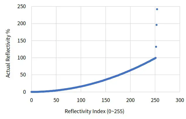
Nonlinear Reflectivity Mapping (Continued on the Next Page)
| Reflectivity Index (0-255) | Reflectivity (%) | Reflectivity Index (0-255) | Reflectivity (0/0) | Reflectivity Index (0-255) | Reflectivity (%) | Reflectivity Index (0-255) | Reflectivity (%) |
| 0 | 0 | 20 | 0.67 | 40 | 2.69 | 60 | 5.9 |
| 1 | 0.01 | 21 | 0.75 | 41 | 2.81 | 61 | 6.1 |
| 2 | 0.02 | 22 | 0.81 | 42 | 2.94 | 62 | 6.3 |
| 3 | 0.03 | 23 | 0.87 | 43 | 3.07 | 63 | 6.5 |
| 4 | 0.04 | 24 | 0.95 | 44 | 3.21 | 64 | 6.7 |
| 5 | 0.05 | 25 | 1.05 | 45 | 3.36 | 65 | 6.9 |
| 6 | 0.08 | 26 | 1.15 | 46 | 3.5 | 66 | 7.1 |
| 7 | 0.11 | 27 | 1.25 | 47 | 3.64 | 67 | 7.3 |
| 8 | 0.13 | 28 | 1.35 | 48 | 3.79 | 68 | 7.5 |
| 9 | 0.15 | 29 | 1.45 | 49 | 3.93 | 69 | 7.7 |
| 10 | 0.19 | 30 | 1.55 | 50 | 4.08 | 70 | 7.9 |
| 11 | 0.23 | 31 | 1.65 | 51 | 4.25 | 71 | 8.12 |
| 12 | 0.26 | 32 | 1.75 | 52 | 4.42 | 72 | 8.37 |
| 13 | 0.29 | 33 | 1.85 | 53 | 4.58 | 73 | 8.62 |
| 14 | 0.34 | 34 | 1.95 | 54 | 4.75 | 74 | 8.87 |
| 15 | 0.39 | 35 | 2.06 | 55 | 4.92 | 75 | 9.1 |
| 16 | 0.44 | 36 | 2.19 | 56 | 5.1 | 76 | 9.3 |
| 17 | 0.5 | 37 | 2.31 | 57 | 5.3 | 77 | 9.5 |
| 18 | 0.56 | 38 | 2.44 | 58 | 5.5 | 78 | 9.7 |
| 19 | 0.61 | 39 | 2.56 | 59 | 5.7 | 79 | 9.9 |
| 80 | 10.17 | 100 | 15.87 | 120 | 22.83 | 140 | 31.17 |
| 81 | 10.5 | 101 | 16.17 | 121 | 23.25 | 141 | 31.5 |
| 82 | 10.83 | 102 | 16.5 | 122 | 23.75 | 142 | 31.83 |
| 83 | 11.12 | 103 | 16.83 | 123 | 24.17 | 143 | 32.25 |
| 84 | 11.37 | 104 | 17.17 | 124 | 24.5 | 144 | 32.75 |
| 85 | 11.62 | 105 | 17.5 | 125 | 24.83 | 145 | 33.25 |
| 86 | 11.87 | 106 | 17.83 | 126 | 25.25 | 146 | 33.75 |
| 87 | 12.12 | 107 | 18.17 | 127 | 25.75 | 147 | 34.25 |
| 88 | 12.37 | 108 | 18.5 | 128 | 26.17 | 148 | 34.75 |
| 89 | 12.62 | 109 | 18.83 | 129 | 26.5 | 149 | 35.25 |
| 90 | 12.87 | 110 | 19.17 | 130 | 26.83 | 150 | 35.75 |
| 91 | 13.17 | 111 | 19.5 | 131 | 27.25 | 151 | 36.25 |
| 92 | 13.5 | 112 | 19.83 | 132 | 27.75 | 152 | 36.75 |
| 93 | 13.83 | 113 | 20.25 | 133 | 28.17 | 153 | 37.25 |
| 94 | 14.17 | 114 | 20.75 | 134 | 28.5 | 154 | 37.75 |
| 95 | 14.5 | 115 | 21.17 | 135 | 28.83 | 155 | 38.25 |
| 96 | 14.83 | 116 | 21.5 | 136 | 29.25 | 156 | 38.75 |
| 97 | 15.12 | 117 | 21.83 | 137 | 29.75 | 157 | 39.17 |
| 98 | 15.37 | 118 | 22.17 | 138 | 30.25 | 158 | 39.5 |
| 99 | 15.62 | 119 | 22.5 | 139 | 30.75 | 159 | 39.83 |
| 160 | 40.5 | 180 | 51.25 | 200 | 63.25 | 220 | 76.5 |
| 161 | 41.25 | 181 | 51.75 | 201 | 63.75 | 221 | 77.25 |
| 162 | 41.75 | 182 | 52.25 | 202 | 64.5 | 222 | 77.75 |
| 163 | 42.25 | 183 | 52.75 | 203 | 65.25 | 223 | 78.5 |
| 164 | 42.75 | 184 | 53.5 | 204 | 65.75 | 224 | 79.25 |
| 165 | 43.25 | 185 | 54.25 | 205 | 66.25 | 225 | 79.75 |
| 166 | 43.75 | 186 | 54.75 | 206 | 66.75 | 226 | 80.5 |
| 167 | 44.25 | 187 | 55.25 | 207 | 67.5 | 227 | 81.25 |
| 168 | 44.75 | 188 | 55.75 | 208 | 68.25 | 228 | 81.75 |
| 169 | 45.25 | 189 | 56.5 | 209 | 68.75 | 229 | 82.5 |
| 170 | 45.75 | 190 | 57.25 | 210 | 69.5 | 230 | 83.5 |
| 171 | 46.25 | 191 | 57.75 | 211 | 70.25 | 231 | 84.25 |
| 172 | 46.75 | 192 | 58.25 | 212 | 70.75 | 232 | 84.75 |
| 173 | 47.25 | 193 | 58.75 | 213 | 71.5 | 233 | 85.5 |
| 174 | 47.75 | 194 | 59.5 | 214 | 72.25 | 234 | 86.5 |
| 175 | 48.25 | 195 | 60.25 | 215 | 72.75 | 235 | 87.25 |
| 176 | 48.75 | 196 | 60.75 | 216 | 73.5 | 236 | 87.75 |
| 177 | 49.5 | 197 | 61.25 | 217 | 74.25 | 237 | 88.5 |
| 178 | 50.25 | 198 | 61.75 | 218 | 74.75 | 238 | 89.25 |
| 179 | 50.75 | 199 | 62.5 | 219 | 75.5 | 239 | 89.75 |
| 240 | 90.5 |
| 241 | 91.5 |
| 242 | 92.5 |
| 243 | 93.25 |
| 244 | 93.75 |
| 245 | 94.5 |
| 246 | 95.5 |
| 247 | 96.25 |
| 248 | 96.75 |
| 249 | 97.5 |
| 250 | 98.5 |
| 251 | 99.5 |
| 252 | 132 |
| 253 | 196 |
| 254 | 242 |
Appendix VI Legal Notice
Copyright 2021 by Hesai Technology. All rights reserved. Use or reproduction of this manual in parts or its entirety without the authorization of Hesai is prohibited.
Hesai Technology makes no representations or warranties, either expressed or implied, with respect to the contents hereof and specifically disclaims any warranties, merchantability, or fitness for any particular purpose. Further, Hesai Technology reserves the right to revise this publication and to make changes from time to time in the contents hereof without obligation to notify any person of such revision or changes.
HESAI and HESAI logo are registered trademarks of Hesai Technology. All other trademarks, service marks, and company names in this manual or on Hesai’s official website are properties of their respective owners.
The software included in this product contains copyright that is registered under Hesai Technology. Any third party is not permitted, except as expressly permitted by licensor or expressly required by applicable law, to decompile, reverse engineer, disassemble, modify, rent, lease, loan, distribute, sublicense, create derivative works based on the whole or any part of the software.
Hesai Technology Co., Ltd.
Phone: +86 400 805 1233
Website: www.hesaitech.com
Address: Building L2, Hongqiao World Centre, Shanghai, China
Business Email: [email protected]
Service Email: [email protected]
HESAI Wechat
http://weixin.qq.com/r/Fzns9IXEl9jorcGX92wF


