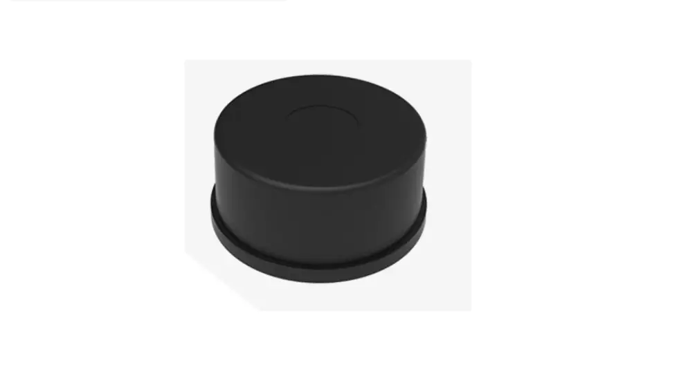
ydlidar 30TG lider SERIES sensor solution
YDLIDAR TG SERIES LIDAR DEVELOPMENT KIT
The development kit of YDLIDAR TG series lidar (including TG15, TG30, TG50 etc) is an accessory tool provided for performance evaluation and early development of the TG. Through the TG development kit, and with the evaluation software, users can observe point cloud data scanned by TG on your environment or development on the SDK.
Development Kit
The TG development kit has the following components: 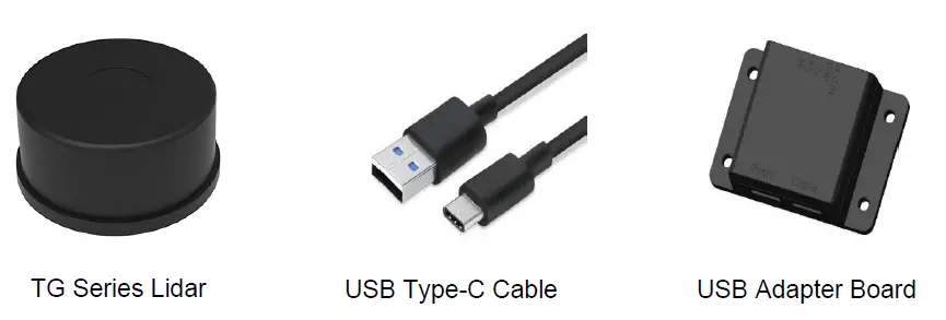
CHART 1 YDLIDAR TG SERIES LIDAR DEVELOPMENT KIT DESCRIPTION
| Item | Qty. | Description |
| TG lidar | 1 | Standard version of the TG series Lidar. The TG has an integrated motor drive for motor control |
| USB Type-C Cable | 1 | Use with USB adapter board to connect TG and PC. USB cable is both a power supply cable and a data cable |
| USB Adapter Board | 1 | Realize USB to UART, convenient for the rapid interconnection of TG series lidar and PC. In addition, it provides Micro USB power interface (PWR) for auxiliary power supply |
Note: USB Adapter board has two USB TYPE C interfaces: USB_DATA、USB_PWR.
USB_DATA: Data-powered interface. In most cases, this interface can be used to meet power and communication requirements.
USB_PWR: Auxiliary power supply interface. The USB interface of some development platforms has weak current drive capability. At this time, auxiliary power supply can be used.
USAGE UNDER WINDOWS
Device Connection
When TG is evaluated and developed under windows, TG and PC need to be interconnected. The specific process is as follows: 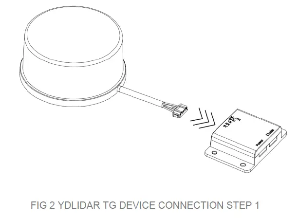
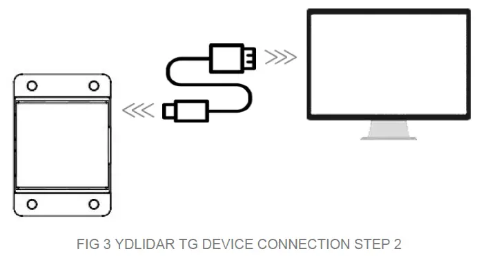
Connect the adapter board with TG first, then connect the USB cable to the USB port of the adapter board and the PC. Note that the Type-C interface of the USB cable is connected to the USB_DATA of the USB interface board, and the idle mode is used after TG is powered on. The motor does not rotate.
The drive current of USB interface of some development platforms or PC is not sufficient. TG Series need to be connected to the auxiliary power supply of +5V, otherwise the radar will be abnormal. 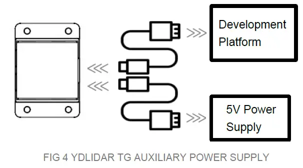
Driver Installation
To evaluate and develop the TG under Windows, you need to install the serial port driver of the USB adapter board. The USB adapter board of this kit adopts CP2102 chip to realize serial port (UART) to USB signal conversion. Its driver can be downloaded from our official website or downloaded from the official website of Silicon Labs.
https://www.ydlidar.com/dowfile.html?id=97
http://cn.silabs.com/products/development-tools/software/usb-to-uart-bridge-vcp-drivers
After unzip the driver package, run the CP2102’s Windows driver installation file (exe file under CP210x_VCP_Windows). Please select the 32-bit version (x86) or 64-bit version (x64) installation program according to the version of the windows operating system. 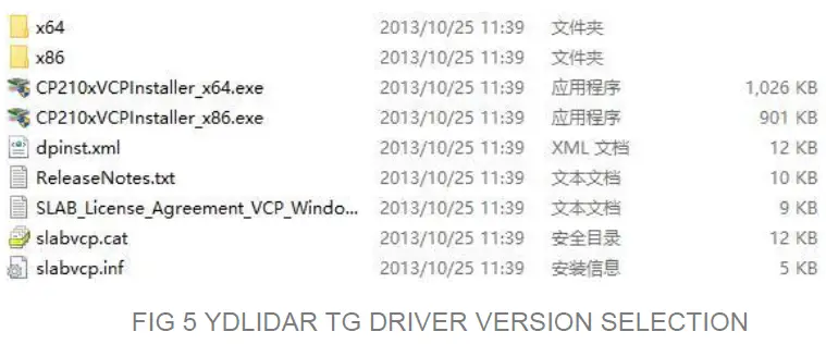
Double-click the exe file and follow the prompts to install it. 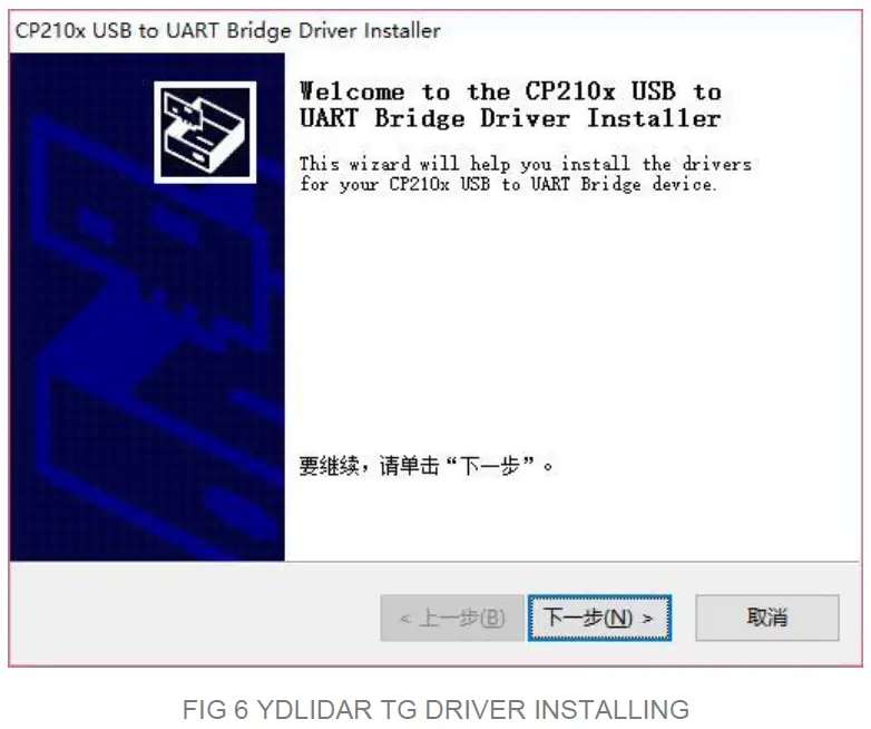
After the installation is complete, you can right-click on [My Computer] and select
[Properties]. On the open [System] screen, select [Device Manager] from the left menu to access the [Device Manager].
Expand [Port] to see the serial port name corresponding to the identified USB adapter, that is, the driver installation is successful. The following figure shows COM3. (Note that the port must be checked in case of TG and PC interconnection). 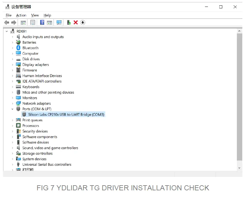
Evaluation Software Usage
YDLIDAR provides Point Cloud Viewer, a point cloud data visualization software for TG real-time scanning. Users can intuitively observe the TG scanning effect chart. GDL real- time point cloud data and real-time scanning frequency are provided on YDLIDAR. At the same time, the version information of TG can be read. Visualization software download link: https://www.ydlidar.cn/Public/upload/download/TOOL.zip
Before using the YDLIDAR software, make sure that the TG USB adapter board serial port driver is installed successfully, and interconnect the TG with the USB port of the PC. Run the evaluation software: LidarViewer.exe, select the corresponding serial port number and model number. You could tick the square box to choose power off protection function. Meanwhile, users could choose language and software type on the top right corner. 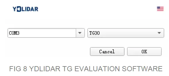
Note: The lidar does not turn on the power off protection function by default. This function needs to send the scan command continuously to make it work normally. If the scanning frequency is stopped, the Lidar will stop scanning.
If the connection is correct, you will see the following screen: 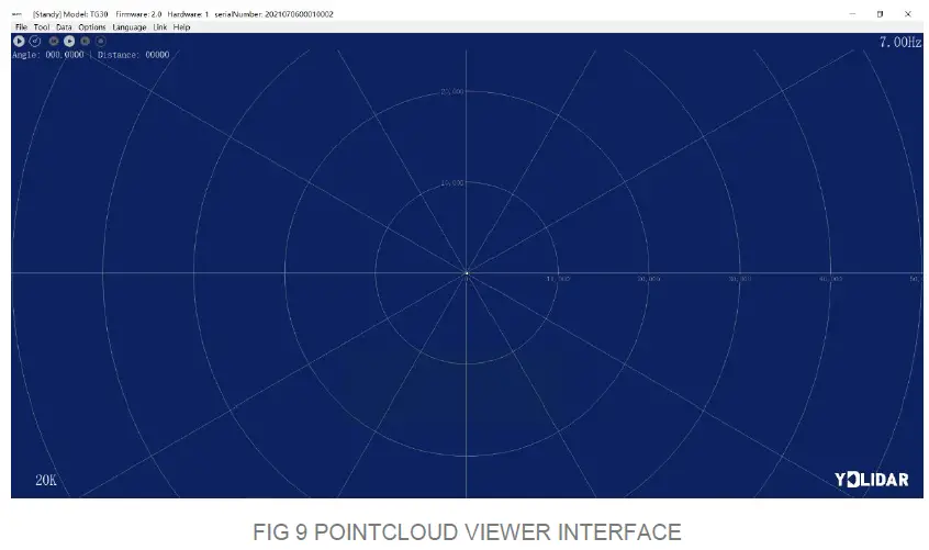
Start Scanning
Click to![]() start scanning and display the environment point cloud. Click
start scanning and display the environment point cloud. Click![]() to stop it. as shown below:
to stop it. as shown below: 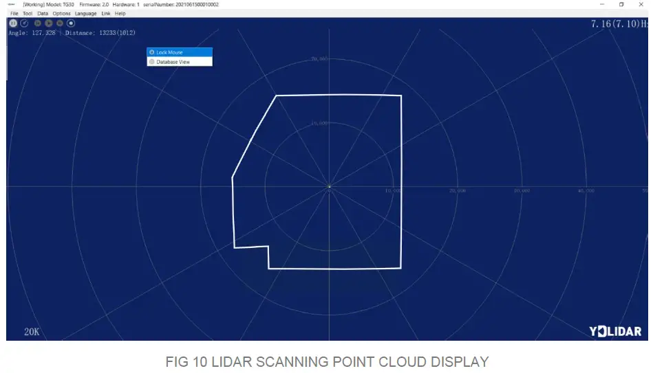
Data Presentation
F(unit: mm) 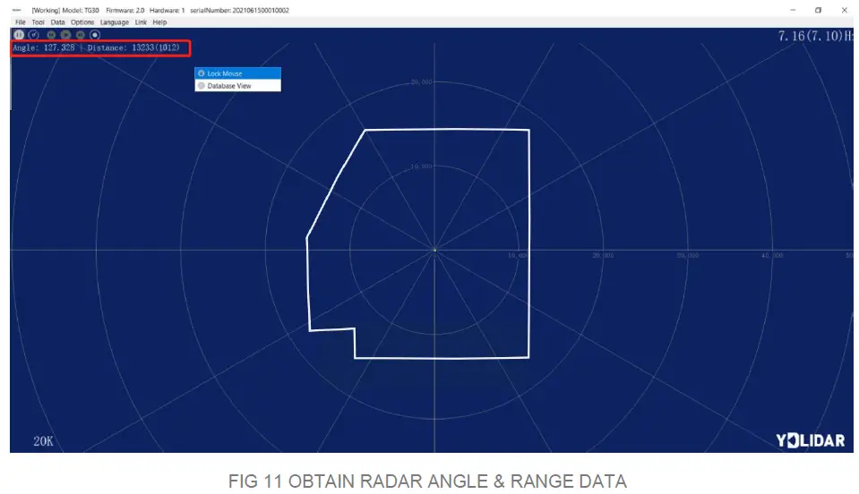
Data Storage
During radar scanning, click [File] in the main menu, select [Export to Excel], and save point cloud data according to the prompts. Then the system will save the point cloud information scanned in a circle in Excel format. 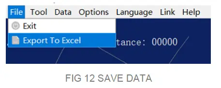 Scan Frequency
 ![]() is used to adjust the scanning frequency (motor speed) of the lidar. Click and drag to adjust according to the demand. When the lidar is in the scanning state, you need to click the scan control again after adjusting the scan frequency.
is used to adjust the scanning frequency (motor speed) of the lidar. Click and drag to adjust according to the demand. When the lidar is in the scanning state, you need to click the scan control again after adjusting the scan frequency. 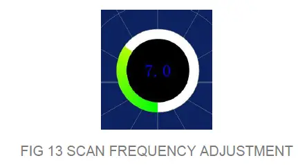
Scan Frequency is used to adjust the scanning frequency (motor speed) of the lidar. Click and drag to adjust according to the demand. When the lidar is in the scanning state, you need to click the scan control again after adjusting the scan frequency
- Turn on the calibration function During radar scanning, click [Tools] in the main menu and select [Zero Adjustment]. These controls
 will be displayed.
 - Adjust angle
Click control to adjust the Angle to the appropriate position.
 - Save configuration
After adjustment, click control , the system will automatically save the calibration parameters, and the calibration will take effect after saving.
Smoothing
Click [Tools] in the main menu, then select [Filtering] to add the lidar data filtering algorithm. 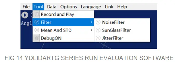
Note: please click [Help] and select [More Information] to learn more about how to use the LidarViewer. (e.g. display mean and standard deviation, playback and recording, debugging, etc.)
LINUX ROS OPERATION
There are many Linux versions,this article only uses Ubuntu 18.04, Melodic version ROS as an example.
SDK driver address:
https://github.com/YDLIDAR/YDLidar-SDK
ROS driver address:
https://github.com/YDLIDAR/ydlidar_ros_driver
Device Connection
Under Linux, the TG and PC interconnect processes are consistent with those under Windows. See Device Connection under Window.
Compile and Install YDLidar-SDK
ydlidar_ros_driver depends on the YDLidar-SDK library. If you have never installed the TDLlidar-SDK library, or it has expired, you must first install the YDLidar-SDK library. If you have the latest version of YDLidar-SDK installed, please skip this step, then go to the next step. 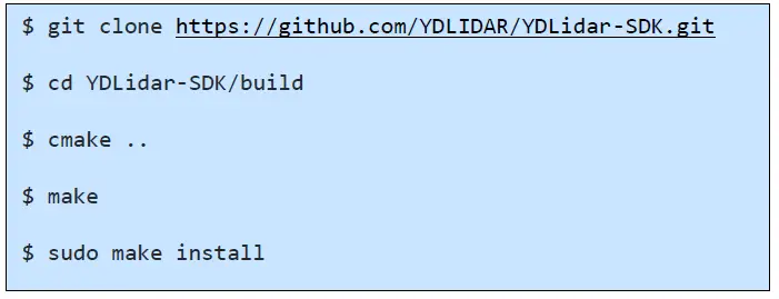
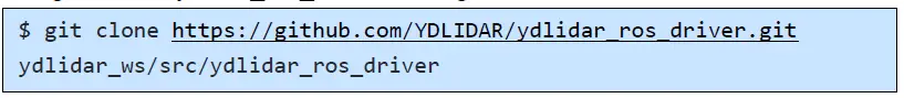
ROS Driver Installation
- Cloning GitHub’s ydlidar_ros_driver Package:

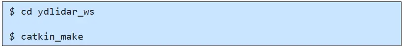
- Build the ydlidar_ros_driver software package:

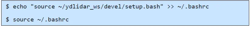
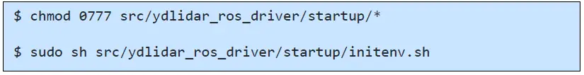
- Package environment Settings:

Note: Add a permanent workspace environment variable. It will be very convenient if ROS environment variables are automatically added to your bash session every time you start a new shell:
- Verify that your package path is set, echo the ROS_PACKAGE_PATH variable.

- You should see something like this: /home/tony/ydlidar_ws/src:/opt/ros/melodic/share Create Serial Port Alias [Optional]


Note: After completing the previous operation, re-insert the LiDAR again.
Run the ydlidar_ros_driver
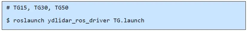
- Run ydlidar_ros_driver with startup file, as shown below:

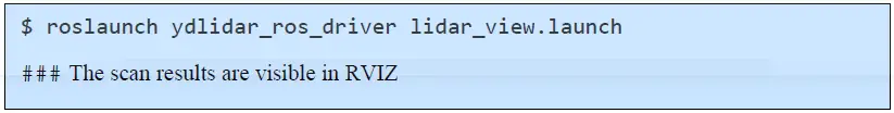
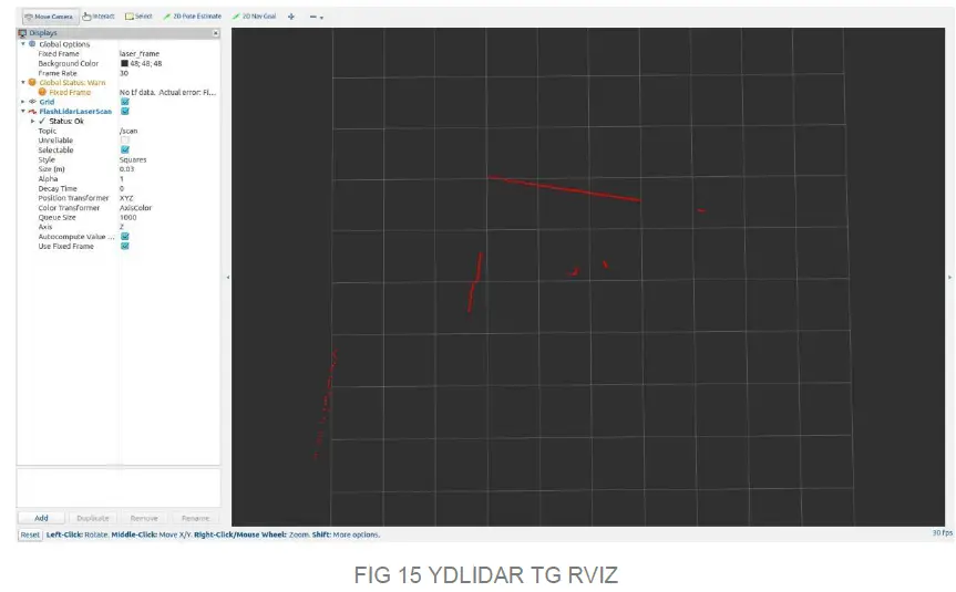
- RVIZ scan result checking

Note: Take G4 as an example by default. If you use other lidars, change the lidar.launch file in lidar_view.launch file to the corresponding **. (If using TG series radar, change to TG. Launch) 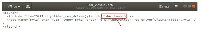
Modify Scan Angle
The scanning data seen by running the launch file is displayed by default with 360- degree data. To modify the display range, you need to modify the configuration parameters in the launch file. The specific operation is as follows:
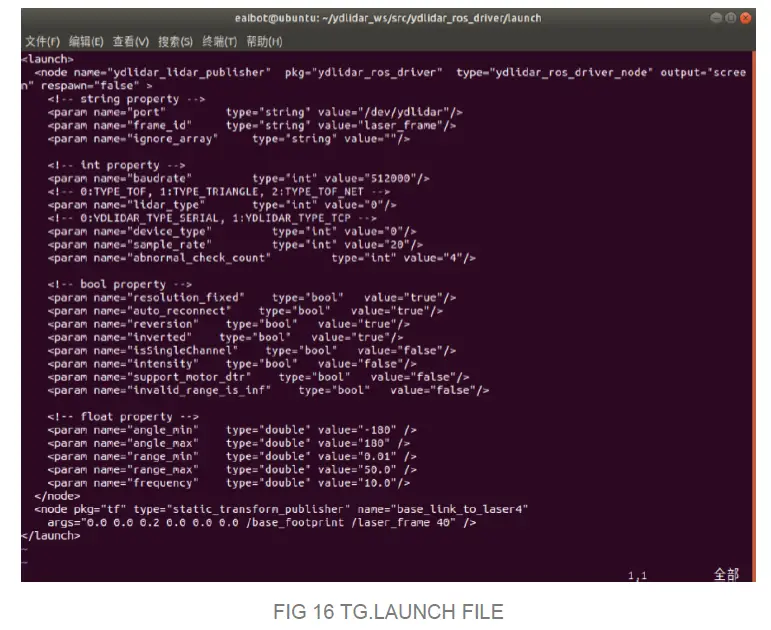
- Go to TG.launch directory and use vim to edit lidar.launch,the contents are as shown in the figure:
$ vim TG.launch Note: For more information about the file contents, please refer to https://github.com/YDLIDAR/ydlidar_ros_driver#configure-ydlidar_ros_driver-internal-parameter
 - The TG lidar coordinates follow the right-hand rule within ROS, with an angle range of [-180, 180]. “angle_min” is the start angle, and “angle_max” is the endangle. The specific scope needs to be modified according to actual use.

 Note: For more information about the file contents, please refer to
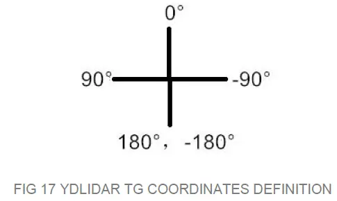
CAUTION
Ambient Temperature
When the working environment temperature of TG is too high or too low, it will affect the accuracy of the distance measuring system. It may also damage the structure of the scanning system and reduce the life of the TG lidar. Avoid use in high temperature (>50 degrees Celsius) and low temperature (<0 degrees Celsius) conditions.
Ambient Lighting
TG use 905nm narrow pulse laser source, optimized optical and electric design enable strong light interference resistance, thus it could meet indoor and outdoor application requirements.
Power Supply
During the development process, since the drive current of the USB interface of each platform or the USB interface of the computer may be too low to drive the TG, the external power supply of the +5V to the TG needs to be provided through the USB_PWR interface of the USB interface board. It is not recommended to use mobile phone power bank because the voltage ripple of power bank is too large.
REVISE
| DATE | VERSION | CONTENT |
| 2019-05-28 | 1.0 | Composing a first draft |
| 2020-01-15 | 1.1 | Client description and information modification |
| 2020-06-09 | 1.2 | Client function description and ROS driver modification |
| 2021-08-02 | 1.3 | Adapt LidarViewer client, update SDK and ROS tutorial |
References
 CP210x USB 至 UART 桥 VCP 驱动器 - 芯科科技
-
Setup.sh
 GitHub - YDLIDAR/ydlidar_ros_driver: ydlidar driver package under ros
-
GitHub - YDLIDAR/ydlidar_ros_driver: ydlidar driver package under ros
-
GitHub - YDLIDAR/ydlidar_ros_driver: ydlidar driver package under ros
-
GitHub - YDLIDAR/YDLidar-SDK: Driver for receiving YD LiDAR data and more...
-
GitHub - YDLIDAR/YDLidar-SDK: Driver for receiving YD LiDAR data and more...
 ydlidar.com/dowfile.html?id=97


