
 MOUSER ELECTRONICS TFmini-i LiDAR Distance Sensor
 Attentions
 Attentions
About this Document
- This Manual provides information necessary for the use of this product.
- Please read this Manual carefully before using this product and make sure that you have fully understood its contents.
1.2 Installation and maintenance
- This product can only be maintained by qualified professionals and only the original spare parts can be used to ensure its performance and safety.
- The working temperature of the product is -20°C~60°C; please do not use it beyond this temperature range, so as to avoid risks.
- The storage temperature of the product is -30°C~75°C; please do not store it beyond this temperature range, so as to avoid risks.
- Do not open its enclosure for assembly or maintenance beyond this Manual; otherwise, it will affect the product performance.
- Do not twist the cable forcefully, so as to avoid damage to product.
- The product can’t be aimed directly to the sun or another TFmini-i, so as to avoid damage the detector by strong light. If there is such an application, please contact our technician.
Conditions with Potential Product Failure
- When the product transmitter and receiver lens are covered by dirt, there will be a risk of failures. Please keep the lens clean.
- The product will have a risk of failure when immersed completely in water. Do not use it underwater.
- When detecting objects with high reflectivity, such as mirrors and smooth tiles, the product may have a high risk of failures.
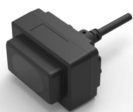
Physical Interface
Wiring
Terminal model: MH1.25-7P-W/B, size of single wire is AWG26, the diameter of single wire is 0.404mm, cross-sectional area is 0.129mm2.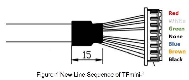
Table 1 Pin functions and connection instructions of TFmini-i
| No. | Color | Pin | Function |
| 1 | Red | VCC | Power supply |
| 2 | White | RS485-B/ CAN_L | RS485-B/CAN bus |
| 3 | Green | RS485-A/ CAN_H | RS485-A/CAN bus |
| 4 | N/A | N/A | N/A |
| 5 | Blue | UART_RX | UART receive(debug) |
| 6 | Brown | UART_TX | UART transport(debug) |
| 7 | Black | GND | Ground |
Note: The hardware of RS485 and CAN is different; Do not mix UART cable with RS485 or CAN bus, otherwise it will cause damage of MCU.
Electrical Characteristics
TFmini-i has overvoltage and polarity protection.
Table 2 Main electrical parameters
| Parameter | Typical value |
| Supply voltage | 7V~30V |
| Peak current | 100mA |
| Average current | ≤65mA@12V |
| Average power consumption | ≤0.8W@12V |
| Overvoltage protection | 30V |
| Polarity protection | 40V |
Hardware and communication protocol
There are two communication interfaces available. The hardware of RS485 and CAN is different. The interface can not be switched by command.
Protocol of RS485
Modbus is the default setting. The parameters is shown as below. The default value of baudrate and slave ID is 115200 and 0x01.
Table 3 Communication protocol of TFmini-i-485
| Item | Parameter |
| Communication interface | RS485 |
| Baud rate | 115200 |
| Data bit | 8 |
| Stop bit | 1 |
| Parity | None |
Parameter configuration and description of Modbus
Baudrate of TFmini-i supports 9600、14400、19200、38400、43000、57600、76800、115200、 128000、230400、256000. Based on reliability considerations, it is not recommended to use a baud rate above 115200 for communication
When Modbus protocol is enabled, the Modbus reading distance command format:
| Address field | Function code | Register address | Number of registers | CRC_low | CRC_high | ||
| 01(default) | 03 | 00 | 00 | 00 | 01 | xx | xx |
The data frame returned by TFmini-i is as follows:
| Address field | Function code | Data length | Dist_high | Dist_low | CRC_low | CRC_high |
| 01(default) | 03 | 02 | xx | xx | xx | xx |
Parameter configuration:
| Category | Function | Instruction | Response | Description |
| UART instructions | Enable Modbus | 5A 05 15 01 75 | 5A 05 15 01 75 | Save settings and restart to take effect. |
| Save settings | 5A 04 11 6F | 5A 05 11 00 70 | ||
| Modbus instructions | DH and DL are 8 high-order |
| CH and CL are 8 high-order | ||||
| and low-order bits of CRC. | ||||
| DH and DL are 8 high-order | ||||
| and low-order bits of | ||||
| Read distance and | 01 03 00 00 00 02 C4 | 01 03 04 DH DL SH SL | Distance; | |
| signal strength | 0B | CL CH | SH and SL are 8 high-order and | |
| low-order bits of signal | ||||
| Strength. | ||||
| Read software | 01 03 00 06 00 02 24 0A | 01 03 04 00 VM VS VC | VM,VS,VC are the major, minor | |
| version | CL CH | and revised version number. | ||
| BH1,BH2,BL1,BL2 are high, | ||||
| secondary high, secondary low | ||||
| 01 06 00 83 BH1 BH2 | 01 06 00 83 BH1 BH2 CL | and low bytes of baud rate. | ||
| Set Baud rate | CL CH 01 06 00 84 BL1 BL2 CL | CH 01 06 00 84 BL1 BL2 CL | For example, set baud rate to 9600,BH1=00 BH2=00 CL=78 | |
| CH | CH | CH=22, | ||
| BL1=25 BL2=80 CL=D2 | ||||
| CH=D3 | ||||
| IH,IL are high and low bytes of | ||||
| Set Slave ID | 01 06 00 85 IH IL CL CH | 01 06 00 84 IH IL CL CH | ID. Set ID to 2,IH=00 IL=02 | |
| CL=19 CH=E2 | ||||
| FH,FL are high and low bytes of | ||||
| Set output rate | 01 06 00 86 FH FL CL CH | 01 06 00 86 FH FL CL CH | frame rate. Set frame rate to 100,FH=00 | |
| FL=64 CL=69 CH=C8 | ||||
| H,LL are high and low bytes of | ||||
| Set low-power consumption mode | 01 06 00 88 LH LL CL CH | 01 06 00 88 LH LL CL CH | low power sampling rate. Set it to 5HZ low-power consumption mode, LH=00 | |
| LL=05 CL=C9 CH=E3 | ||||
| Save settings | 01 06 00 80 00 00 88 22 | 01 06 00 80 00 00 88 22 | Save settings and restart to | |
| take effect | ||||
| Restore factory | 01 06 00 89 00 00 58 20 | 01 06 00 89 00 00 58 20 | ||
| setting | ||||
| Disable Modbus | 01 06 00 82 00 01 E8 22 | 01 06 00 82 00 01 E8 22 | Save settings and restart to | |
| take effect |
Note: Only RTU mode is supported for communication in UART link.
Function code of TFmini-i Modbus
| Function code | Description |
| 03 | Read register |
| 06 | Write register |
Register address description
- All register addresses are hexadecimal and register values are 16bit;
- After setting parameter, save and restart to take effect;
Register address list using function code: 0x03(read only)
| Register address | Definition | Description |
| 00 00 | Dist | Distance, unit: cm |
| 00 01 | Strength | Signal strength |
| 00 03 | High16bit of timestamp | 2 high-order bits of timestamp represent relative time of radar start up, unit: ms |
| 00 04 | Low16bit of timestamp | 2 low-order bits of timestamp represent relative time of radar start up, unit: ms |
| 00 06 | High16bit of software version | 00 + major version number |
| 00 07 | Low16bit of software version | Minor version number + revised version number |
Register address list using function code: 0x06(write only)
| Register address | Definition | Description |
| 00 80 | Save settings | Write any value to save settings |
| 00 81 | Power off/Restart | Register value: 0-Power off(unavailable currently) 1-Restart; |
| 00 82 | Disable Modbus | Register value: 1-Disable Modbus Others-Error reply |
| 00 83 | Baud rate High | Set baud rate. Restart to take effect |
| 00 84 | Baud rate Low | Set baud rate. Restart to take effect |
| 00 85 | Slave ID | Set TFmini-i’s ID. Restart to take effect(default 0x01) |
| 00 86 | fps | Set fps. Restart to take effect(default 100hz) |
|
00 87 |
Working mode | Set working mode. Restart to take effect after saving Register value: 0- Continuously detection mode(default) 1-Triggering mode Others-Error reply |
|
00 88 |
Low-power consumption mode | Set low-power consumption mode,Restart to take effect after saving Register value: 0-Disable(default) >0 and≤10-Enable(the value is inside sampling frequent) |
| 00 89 | Restore default | Write any value. Restart to take effect after saving |
Examples
- Enable Modbus protocoL
- 5A 05 15 01 75 // Enable Modbus
- 5A 04 11 6F // Save settings Entry Modbus model and entry Modbus instructions after restarting
- Disable Modbus protocoL
- 01 06 00 82 00 01 E8 22// Default address 01, disable Modbus
- // Default address 01, save setting 01 06 00 80 00 00 88 22 Restart and exit Modbus.
Protocol of CAN
The data protocol of CAN is shown in
Table 4. Each data frame consists of 8 bytes and the data contains the distance(unit: cm), signal strength and timestamp(unit: ms) information.
Table 4 Data protocol of TFmini-i-CAN
| Data byte | Definition | Description |
| Byte0 | DIST_L | DIST low 8-bits |
| Byte1 | DIST_H | DIST high 8-bits |
| Byte2 | Strength_L | Signal strength low 8-bits |
| Byte3 | Strength_H | Signal strength high 8-bits |
| Byte4 | Timestamp | Low8bit of timestamp |
| Byte5 | Timestamp | Secondary-low8bit of timestamp |
| Byte6 | Timestamp | Secondary-high8bit of timestamp |
| Byte7 | Timestamp | High8bit of timestamp |
Parameter configuration and description of CAN
The default baudrate is 250kbps, the default type is standard frame, default receive and send id is 0x00000003.
The format of instruction is shown as below:
| Byte | 0 | 1 | 2 | 3 | 4 | 5-8 | 9-12 | 13 |
| Description | 0x5A | 0x0E | 0x51 | Type | Baudrate | Recv_id | Send_id | Check_sum |
| Default | 0 | 8 | 0x00000003 | 0x00000003 |
Type: 0(Standard Frame), 1(Extended Frame);
Received: LiDAR receive ID, Little Endian; Send_id: LiDAR send ID, Little Endian
The relation between Baudrate(unit: kbps) and Byte4 is shown as below:
| Byte4 | 0 | 1 | 2 | 3 | 4 | 5 | 6 | 7 | 8 | 9 | 10 | 11 | 12 | 13 | 14 | 15 | 16 |
| Baudrate | 1000 | 900 | 800 | 666 | 600 | 500 | 400 | 300 | 250 | 225 | 200 | 160 | 150 | 144 | 125 | 120 | 100 |
- Examples of configuration
- Example1: Standard frame, Baud rate 500kbps, receive ID=0x0010, send ID=0x0020 Command: 5A 0E 51 00 05 10 00 00 00 20 00 00 00 EE
- Example2: Extended Frame, Baud rate 250kbps, receive ID=0x0000AABB, send ID=0x0000CCDD
- Command: 5A 0E 51 01 08 BB AA 00 00 DD CC 00 00 D0
- CAN Terminating Resistor Configuration Instructions
Enable 120Ω Terminating Resistor: 5A 05 60 01 C0
Disable(Default) 120Ω Terminating Resistor: 5A 05 60 00 BF - Others
- Other configuration instructions are the same as UART instructions of standard products, such as saving settings(5A 04 11 6F), resetting(5A 04 02 60) and so on. “Save setting” instruction must be sent after setting parameters, otherwise the parameter doesn’t take effect after restarting.
- When the command is longer than 8 bytes, it needs to be distributed into multiple CAN data frames. And interval between every data frame can’t be longer than 20ms.\
FAQ
- Can the FOV (spot) of TFmini-i be increased or decreased?
A1: Generally, this is a customized demand. You need to contact our sale colleague for further details. FOV is determined at the beginning of product design. Determination of FOV is also related to the optical system and the product structure. Therefore, it cannot be easily changed and needs to be customized. - Can I change the frequency of data output?
A2: Yes, customization of parameter configuration is supported in TFmini-i. You may consult our sales colleague or technical support for further details. Other common questions please refer to SJ-PM-TFmini-S A01 Product Manual on our website.


