Benewake TFmini-i LiDAR Distance Sensors
Foreword
Dear users:
Thanks for choosing Benewake products, and it’s our pleasure to help you to solve any technical question. For the purpose of offering a better operation experience to you, we hereby write this manual for an easier and simpler operation of our product, hoping to better solve the common problems you maybe meet. This operation manual covers the product operation introduction and common problem solutions, but it is really hard to cover all the problems you maybe meet. So, if you have any further questions or problems, please feel free to consult our technical support service ([email protected]). We will do our best to solve any problem related to the product. If you have any other good advice or suggestions, welcome to visit our official website and offer us your feedback there (http://en.benewake.com/support), and we are looking forwards to your participation. We are Benewake who dedicated to making the best “Robotic Eyes” worldwide!
Attentions
About this Document
- This Manual provides information necessary for the use of this product.
- Please read this Manual carefully before using this product and make sure that you have fully understood its contents.
Installation and maintenance
- This product can only be maintained by qualified professionals and only the original spare parts can be used to ensure its performance and safety.
- The working temperature of the product is -20°C~60°C; please do not use it beyond this temperature range, so as to avoid risks.
- The storage temperature of the product is -30°C~75°C; please do not store it beyond this temperature range, so as to avoid risks.
- Do not open its enclosure for assembly or maintenance beyond this Manual; otherwise, it will affect the product performance.
- Do not twist the cable forcefully, so as to avoid damage to the product.
- The product can’t be aimed directly to the sun or another TFmini-i, so as to avoid damage the detector by strong light. If there is such an application, please contact our technician.
Conditions with Potential Product Failure
- When the product transmitter and receiver lens are covered by dirt, there will be a risk of failures. Please keep the lens clean.
- The product will have a risk of failure when immersed completely in water. Do not use it underwater.
- When detecting objects with high reflectivities, such as mirrors and smooth tiles, the product may have a high risk of failure.
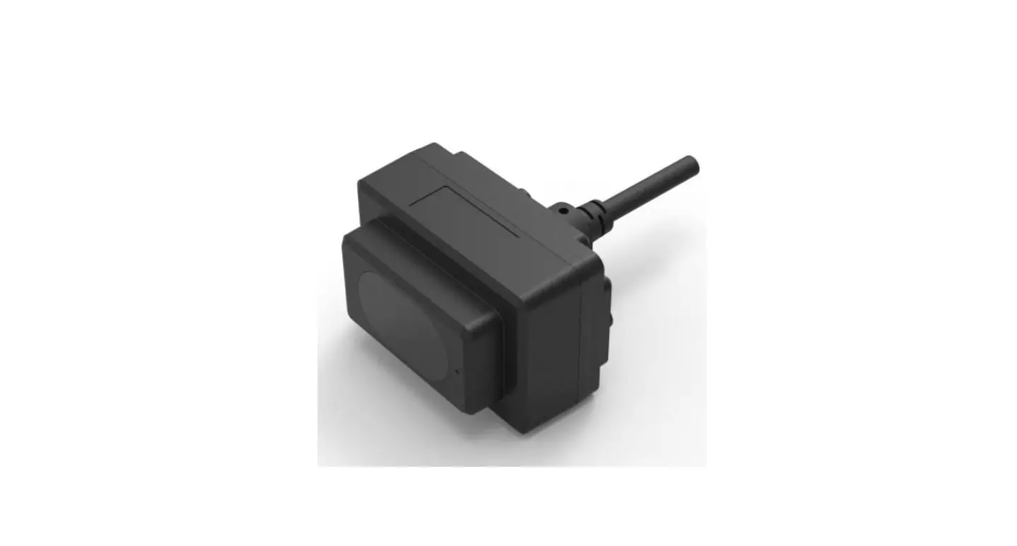
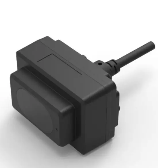
Physical Interface
Wiring
Terminal model: MH1.25-7P-W/B, size of single wire is AWG26, the diameter of single wire is 0.404mm, and cross-sectional area is 0.129mm2.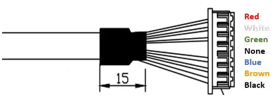
| No. | Color | Pin | Function |
| 1 | Red | VCC | Power supply |
| 2 | White | RS485-B/ CAN_L | RS485-B/CAN bus |
| 3 | Green | RS485-A/ CAN_H | RS485-A/CAN bus |
| 4 | N/A | N/A | N/A |
| 5 | Blue | UART_RX | UART receive(debug) |
| 6 | Brown | UART_TX | UART transport(debug) |
| 7 | Black | GND | Ground |
Note: The hardware of RS485 and CAN is different; Do not mix UART cable with RS485 or CAN bus, otherwise it will cause damage of MCU.
Electrical Characteristics
TFmini-i has overvoltage and polarity protection.
| Parameter | Typical value |
| Supply voltage | 7V~30V |
| Peak current | 100mA |
| Average current | ≤65mA@12V |
| Average power consumption | ≤0.8W@12V |
| Overvoltage protection | 30V |
| Polarity protection | 40V |
Hardware and communication protocol
There are two communication interfaces available. The hardware of RS485 and CAN is different. The interface can not be switched by command.
Protocol of RS485
Modbus is the default setting. The parameters is shown as below. The default value of baudrate and slave ID is 115200 and 0x01.
| Item | Parameter |
| Communication interface | RS485 |
| Baud rate | 115200 |
| Data bit | 8 |
| Stop bit | 1 |
| Parity | None |
Parameter configuration and description of Modbus
Baudrate of TFmini-i supports 9600、14400、19200、38400、43000、57600、76800、115200、 128000、230400、256000. Based on reliability considerations, it is not recommended to use a baud rate above 115200 for communication When Modbus protocol is enabled, the Modbus reading distance command format:
| Address field | Function code | Register address | Number of registers | CRC_low | CRC_high | ||
| 01(default) | 03 | 00 | 00 | 00 | 01 | xx | xx |
The data frame returned by TFmini-i is as follows:
| Address field | Function code | Data length | Dist_high | Dist_low | CRC_low | CRC_high |
| 01(default) | 03 | 02 | xx | xx | xx | xx |
Parameter configuration:
| Category | Function | Instruction | Response | Description |
| UART instructions | Enable Modbus | 5A 05 15 01 75 | 5A 05 15 01 75 | Save settings and restart to take effect. |
| Save settings | 5A 04 11 6F | 5A 05 11 00 70 | ||
| Modbus instructions | DH and DL are 8 high-order |
| CH and CL are 8 high-order | ||||
| and low-order bits of CRC. | ||||
| DH and DL are 8 high-order | ||||
| and low-order bits of | ||||
| Read distance and | 01 03 00 00 00 02 C4 | 01 03 04 DH DL SH SL | Distance; | |
| signal strength | 0B | CL CH | SH and SL are 8 high-order and | |
| low-order bits of signal | ||||
| Strength. | ||||
| Read software | 01 03 00 06 00 02 24 0A | 01 03 04 00 VM VS VC | VM,VS,VC are the major, minor | |
| version | CL CH | and revised version number. | ||
| BH1,BH2,BL1,BL2 are high, | ||||
| secondary high, secondary low | ||||
| 01 06 00 83 BH1 BH2 | 01 06 00 83 BH1 BH2 CL | and low bytes of baud rate. | ||
| Set Baud rate | CL CH 01 06 00 84 BL1 BL2 CL | CH 01 06 00 84 BL1 BL2 CL | For example, set baud rate to 9600,BH1=00 BH2=00 CL=78 | |
| CH | CH | CH=22, | ||
| BL1=25 BL2=80 CL=D2 | ||||
| CH=D3 | ||||
| IH,IL are high and low bytes of | ||||
| Set Slave ID | 01 06 00 85 IH IL CL CH | 01 06 00 84 IH IL CL CH | ID. Set ID to 2,IH=00 IL=02 | |
| CL=19 CH=E2 | ||||
| FH,FL are high and low bytes of | ||||
| Set output rate | 01 06 00 86 FH FL CL CH | 01 06 00 86 FH FL CL CH | frame rate. Set frame rate to 100,FH=00 | |
| FL=64 CL=69 CH=C8 | ||||
| H,LL are high and low bytes of | ||||
| Set low-power consumption mode | 01 06 00 88 LH LL CL CH | 01 06 00 88 LH LL CL CH | low power sampling rate. Set it to 5HZ low-power consumption mode, LH=00 | |
| LL=05 CL=C9 CH=E3 | ||||
| Save settings | 01 06 00 80 00 00 88 22 | 01 06 00 80 00 00 88 22 | Save settings and restart to | |
| take effect | ||||
| Restore factory | 01 06 00 89 00 00 58 20 | 01 06 00 89 00 00 58 20 | ||
| setting | ||||
| Disable Modbus | 01 06 00 82 00 01 E8 22 | 01 06 00 82 00 01 E8 22 | Save settings and restart to | |
| take effect |
Note: Only RTU mode is supported for communication in UART link.
Function code of TFmini-i Modbus
| Function code | Description |
| 03 | Read register |
| 06 | Write register |
Register address description
- All register addresses are hexadecimal and register values are 16bit;
- After setting parameter, save and restart to take effect;
Register address list using function code: 0x03(read only)
| Register address | Definition | Description |
| 00 00 | Dist | Distance, unit: cm |
| 00 01 | Strength | Signal strength |
| 00 03 | High16bit of timestamp | 2 high-order bits of timestamp represent relative time of radar start up, unit: ms |
| 00 04 | Low16bit of timestamp | 2 low-order bits of timestamp represent relative time of radar start up, unit: ms |
| 00 06 | High16bit of software version | 00 + major version number |
| 00 07 | Low16bit of software version | Minor version number + revised version number |
Register address list using function code: 0x06(write only)
| Register address | Definition | Description |
| 00 80 | Save settings | Write any value to save settings |
| 00 81 | Power off/Restart | Register value: 0-Power off(unavailable currently) 1-Restart; |
| 00 82 | Disable Modbus | Register value: 1-Disable Modbus Others-Error reply |
| 00 83 | Baud rate High | Set baud rate. Restart to take effect |
| 00 84 | Baud rate Low | Set baud rate. Restart to take effect |
| 00 85 | Slave ID | Set TFmini-i’s ID. Restart to take effect(default 0x01) |
| 00 86 | fps | Set fps. Restart to take effect(default 100hz) |
|
00 87 |
Working mode | Set working mode. Restart to take effect after saving Register value: 0- Continuously detection mode(default) 1-Triggering mode Others-Error reply |
|
00 88 |
Low-power consumption mode | Set low-power consumption mode,Restart to take effect after saving Register value: 0-Disable(default) >0 and≤10-Enable(the value is inside sampling frequent) |
| 00 89 | Restore default | Write any value. Restart to take effect after saving |
Examples:
- Enable Modbus protocol:
- 5A 05 15 01 75 // Enable Modbus
- 5A 04 11 6F // Save settings
- Disable Modbus protocol:
- 01 06 00 82 00 01 E8 22 // Default address 01, disable Modbus
- 01 06 00 80 00 00 88 22 // Default address 01, save setting
Protocol of CAN
The data protocol of CAN is shown in Table 4. Each data frame consists of 8 bytes and the data contains the distance(unit: cm), signal strength and timestamp(unit: ms) information.
| Data byte | Definition | Description |
| Byte0 | DIST_L | DIST low 8-bits |
| Byte1 | DIST_H | DIST high 8-bits |
| Byte2 | Strength_L | Signal strength low 8-bits |
| Byte3 | Strength_H | Signal strength high 8-bits |
| Byte4 | Timestamp | Low8bit of timestamp |
| Byte5 | Timestamp | Secondary-low8bit of timestamp |
| Byte6 | Timestamp | Secondary-high8bit of timestamp |
| Byte7 | Timestamp | High8bit of timestamp |
Parameter configuration and description of CAN
The default baudrate is 250kbps, the default type is standard frame, default receive and send id is 0x00000003.
The format of instruction is shown as below:
| Byte | 0 | 1 | 2 | 3 | 4 | 5-8 | 9-12 | 13 |
| Description | 0x5A | 0x0E | 0x51 | Type | Baudrate | Recv_id | Send_id | Check_sum |
| Default | 0 | 8 | 0x00000003 | 0x00000003 |
Type: 0(Standard Frame), 1(Extended Frame);
Recv_id: LiDAR receive ID, Little Endian; Send_id: LiDAR send ID, Little Endian
The relation between Baudrate(unit: kbps) and Byte4 is shown as below:
| Byte4 | 0 | 1 | 2 | 3 | 4 | 5 | 6 | 7 | 8 | 9 | 10 | 11 | 12 | 13 | 14 | 15 | 16 |
| Baudrate | 1000 | 900 | 800 | 666 | 600 | 500 | 400 | 300 | 250 | 225 | 200 | 160 | 150 | 144 | 125 | 120 | 100 |
- Examples of configuration
Example1: Standard frame, Baud rate 500kbps, receive ID=0x0010, send ID=0x0020 Command: 5A 0E 51 00 05 10 00 00 00 20 00 00 00 EE
Example2: Extended Frame, Baud rate 250kbps, receive ID=0x0000AABB,
send ID=0x0000CCDD
Command: 5A 0E 51 01 08 BB AA 00 00 DD CC 00 00 D0 - CAN Terminating Resistor Configuration Instructions
Enable 120Ω Terminating Resistor: 5A 05 60 01 C0
Disable(Default) 120Ω Terminating Resistor: 5A 05 60 00 BF - Others
- Other configuration instructions are the same as UART instructions of standard products, such as saving settings(5A 04 11 6F), resetting(5A 04 02 60) and so on. “Save setting” instruction must be sent after setting parameters, otherwise the parameter doesn’t take effect after restarting.
- When the command is longer than 8 bytes, it needs to be distributed into multiple CAN data frames. And the interval between every data frame can’t be longer than 20ms.
FAQ
- Q1: Can the FOV (spot) of TFmini-i be increased or decreased?
A1: Generally, this is a customized demand. You need to contact our sales colleague for further details. FOV is determined at the beginning of product design. Determination of FOV is also related to the optical system and the product structure. Therefore, it cannot be easily changed and needs to be customized. - Q2: Can I change the frequency of data output?
A2: Yes, customization of parameter configuration is supported in TFmini-i. You may consult our sales colleague or technical support for further details. Other common questions please refer to SJ-PM-TFmini-S A01 Product Manual on our website.
Headquarters:
400-880-9610
Technical support:
[email protected] [email protected]
Specified Product
Product model: TFmini-i
Product name: TFmini-i LiDAR
Manufacturer
Company name: Benewake (Beijing) Co., Ltd. Address: NO.28 Xinxi Road, Haidian District, Beijing, PRC
Copyright
The Copyright of this document is protected. All the rights involved herein belong to Benewake (Beijing) Co., Ltd. Any copy activity of this document, no matter in whole or in part, should be in conformity of the Copyright Law. The actives of modification, omission or translation of this document are not allowed unless written permission from Benewake (Beijing) Co., Ltd. All rights reserved © Benewake (Beijing) Co., Ltd.


