doorKNOX VDP304 Door Entry Monitors Instruction Manual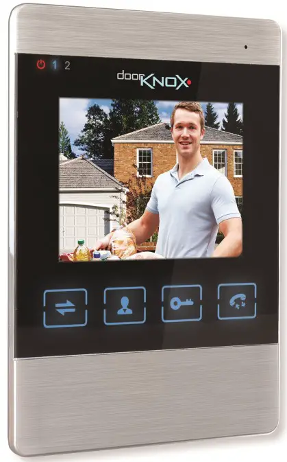
Introduction
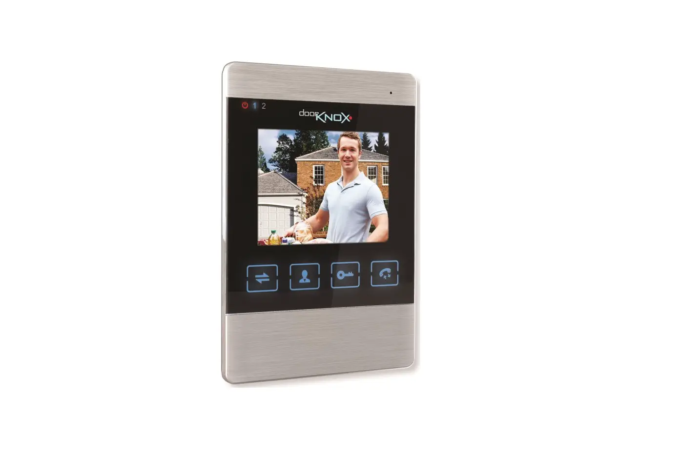
The VDP304 has a stylish brushed aluminium & gloss black finish. The quality build the DoorKnox is ideal for domestic, retail and commercial projects.
The menu interface has an updated modern design, showing coloured icons, for easy use of the menu.*
Our touch button monitor provides control of the door entry camera and is available in a 4″ size.
Two door cameras and two door locks can be connected to the main monitor.
The menu structure in the VDP304 does not match the latest VDP207 and VDP210 monitors, but they can be used in conjunction with each other.
DoorKnox Monitors from serial numbers VDP207 (HCA01001) & VDP210 (HCB00401) can be used along side the VDP304.
Key Features
- Up to 4 monitors on a system. 1 Main Monitor plus 3 Auxiliary Monitors.
- Camera to Monitor Intercom
- Monitor to Monitor Intercom
- 12 built ringtones
- Customise ringtone MP3
- Motion detection
- Ring at camera
- Automated Message & Video Mail Recording
- Local Unlock
- Standby Screen Saver Customisation
- Media Player – Music, Video & Pictures
User Information
- Do not expose to moisture or high humidity conditions. This product is rated for internal use only.
- Take care when transporting, storing and installing the monitor
- Always use and conform to current standards to install and use these. The signal cables should be kept way from high voltage equipment. Damage to units by lightning or mains voltage surges is not covered under the product warranty.(BS EN 62676-1-1) (BS EN 62676-4) (BS8418)
- There are no user serviceable parts in the monitor and opening or attempting to repair the product will void the warranty.
- Do not touch the connections with wet hands.
- Wipe dirt away with a damp micro-fibrecloth.
- Do not install or use the monitor if the cables, casing, or the power supply is damaged.
Connections and Wiring
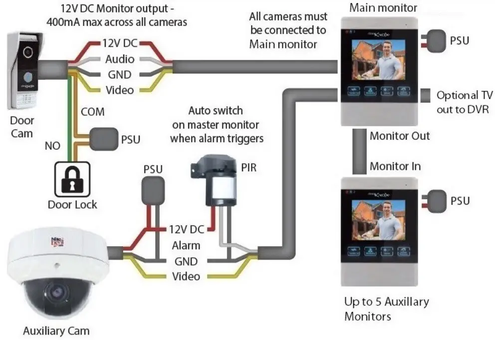
To make life easier all monitors feature the exact same connection layout as shown below: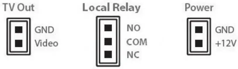
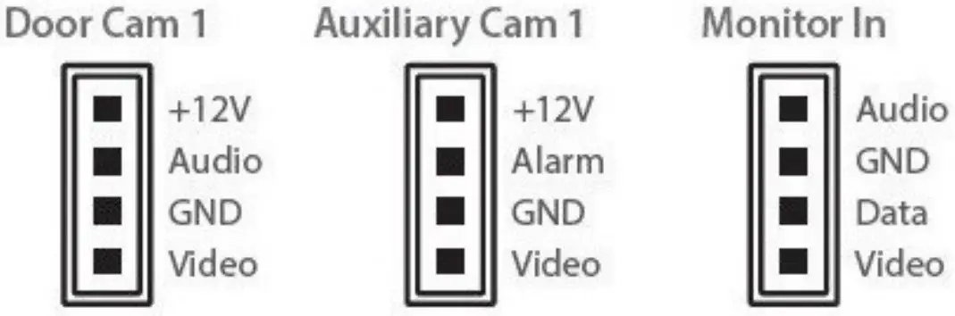
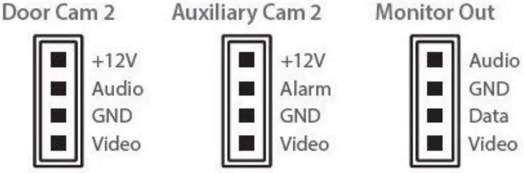
Cameras
All of the DoorKnox cameras have connection cables terminated into the same 7 colour coordinated wires. 4 wires are used to connect to the monitor and then 2 of the 3 remaining wires are used to connect to an electronic door lock.
The common (COM) wire is always used along with either the normally open (NO) or normally closed (NC) wire depending on the lock type, power for the lock is separate as the Door Lock relay does not provide output.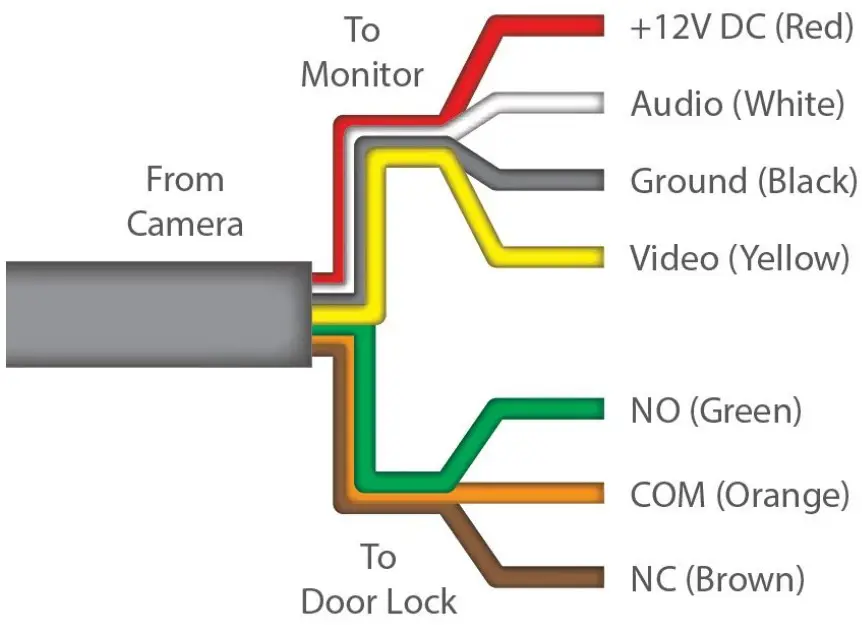
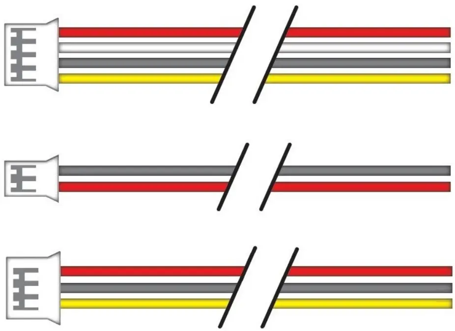
Monitors
Every monitor is supplied with 5x 4 wire y-leads, 1x 2 wire y-lead and 1x 3 wire ylead.
The 4 wire y-leads are terminated into 4 pin plugs which are simply inserted into the sockets on the rear of the monitor. These are used for connecting door cameras, auxiliary cameras and auxiliary monitors, the 4 wires are colour co-ordinated to match the 4 wires from the door camera.
The 2 wire y-lead is terminated with a 2 pin plug and is used as the TV out for connecting the door monitor to a TV monitor or DVR.
The 3 wire y-lead is terminated for the local relay plug and is used to unlock a local relay like a door release local to the monitor.
Powering Cameras
Door cameras and auxiliary cameras can be powered in two ways, either locally or via the main monitor.
The DoorKnox monitors can supply a 12V DC output to any of the four cameras but can only supply a maximum of 400mA across all outputs.
To power a camera locally connect the Audio (white) and Video (yellow) to the door monitor, the GND (black) to the PSU and the door monitor and then the 12V DC (red) to the PSU only.
Powering Monitors
Door monitors are supplied with a 12V DC 2A plug-in PSU that terminates into a 2 pin plug which slots into the rear of the monitor.
Cable Runs
The maximum achievable cable run is limited by the voltage drop in the chosen cable and also the quality of the video cable which can cause signal loss and interference.
Resistance differs depending on the cable used and the higher the resistance the more the voltage drops hence the shorter cable run achievable.
ltis recommended to use one of three types of cable, PTZ combo cable sometimes known as RG59+4, CAT5+2 cable or 4 core cable with 0.3mm2 cores.
Below shows the maximum recommended cable run for each cable type. Cable runs exceeding the stated maximum run are at risk of issues caused by voltage drop and non performance of equipment.
Camera to Main Monitor
| ICable Type | Max Cable Run |
| PTZ Combo Cable (RG59+4) | |Up To 150m |
| ICAT5+2 Up To 100m ICAT5+2 Up To 100m | Up To 100m |
| 4 Core Cable (0.3mm2) | Up To 50m |
Main Monitor to Auxiliary Monitors
| Cable Type | Max Cable Run |
| PTZ Combo Cable (RG59+4) | Up To 30m (Per Monitor) |
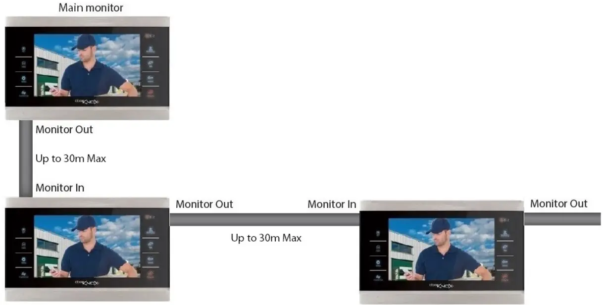
Mounting
Mark the hole positions using the mounting bracket.
Drill the holes and install the wall plugs.
Secure the mounting plate and then slot the monitor onto the bracket, when the monitor clicks it is secured in place.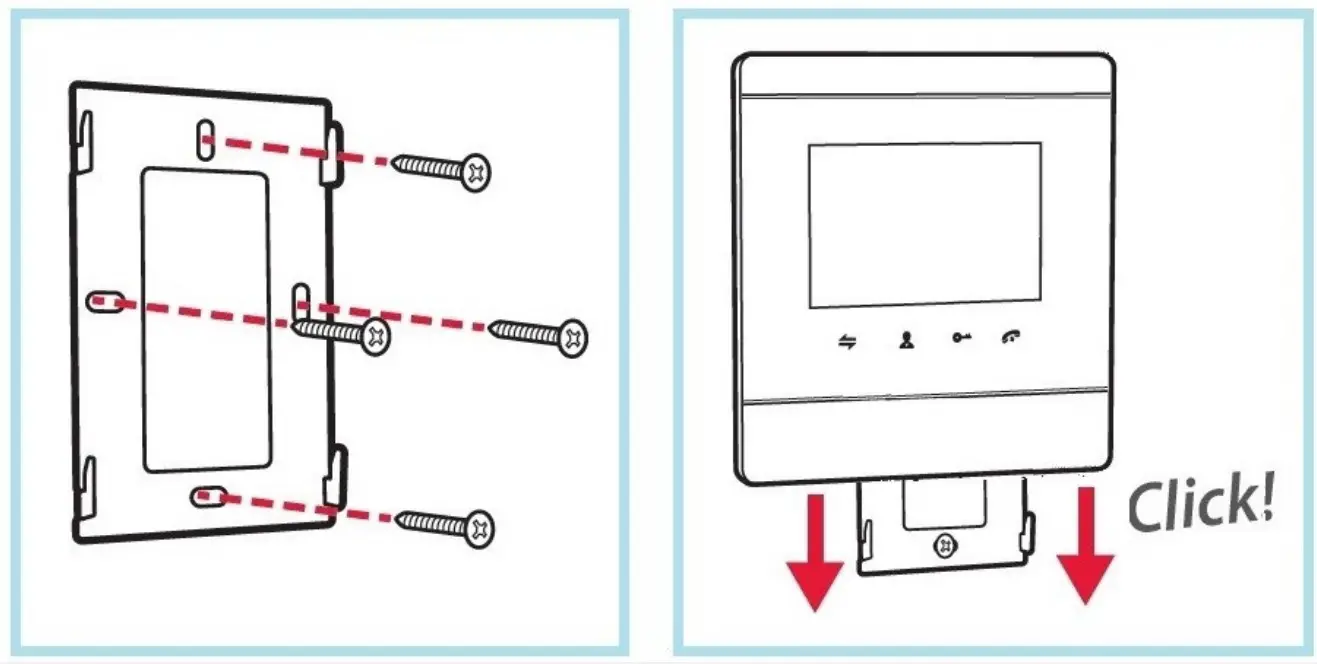
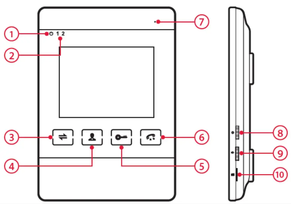
Controls and Features
- Power Indicator
- Indicator shows which camera is being displayed
- Transfer – Send call to other monitor(s) / Intercom
- Monitoring – Switch between camera inputs
- Unlock – Sends command to unlock
- Talk – Answer/ End call / Retum
- Microphone
- Settings – Enter / Up and down
- Volume Control
- Micro SD card slot
Setting button on the side of the monitor –
- Press in to enter the menu.
- Flick up / down to navigate the menu system
- Press again to make selection
Talk (Answer/ hang up) intercom button –
- To go back at any time or to exit the menu use the Talk button.
- Repeatedly pressing this button from any page will take you out of the settings.
- Any settings that you have made will be automatically saved.
Basic Monitor Settings
If only using 1 door camera and 1 monitor then skip setting monitor ID and camera switch.
Setting Monitor ID
Up to 4 DoorKnox monitors can be used; 1 main monitor and up to 3 auxiliary monitors.
The main monitor ID must be set to 1, and the auxiliary monitors ID from 2 up.
- Press the Setting button on the side of the monitor to access the menu.
- Using the Setting button flick up / down to navigate to “Mode” in the menu, then press the Setting button.
- Navigate to “Device ID” then press Setting button, flick up / down to change the ID.
Setting the Time
- Press the Setting button on the side of the monitor to access the menu.
- Using the Setting button flick up / down to navigate to “Time” in the menu, then press the Setting button.
- Flick up / down to navigate the page and then press the Setting button to select the setting, use up / down to change the setting.
Using the Door Entry System
Visitor Calls
When a visitor presses the call button on a door camera the ringtone will be played and their image will be displayed on all door monitors. To answer the call v press the Talk button.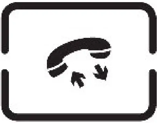
Monitoring Cameras
To monitor any camera press the Monitoring button to cycle through camera inputs.
When monitoring a door camera open two way audio by pressing the Talk button.
Unlock door by pressing the Unlock button.
When monitoring cameras the door monitor will return to standby after 60 seconds of inactivity.
Local Relay / Unlock
The local relay to the monitor can be wired to unlock a door from the monitor using its local relay.
Press and hold Unlock to activate local relay.
Intercom (Monitor to Monitor Audio)
Press the Transfer button to show different monitor extension IDs
Press the Up / Down to select the different monitor
IDs then select using Setting to call another monitor.
To answer the call press the Talk button on the receiving monitor.
To end the call press the Hang Up Button.
| Language | Language | English / ltalian / Lithuanian / Turkish / Dutch / Spanish / Slovakian / Czech / French / Ukrainian / Polish / Russian / Traditional Chinese / Simplified Chinese |
| Time | Clock | On / off |
| Format | YY-MM-DD / DD-MM-YY/ MM-DD-YY | |
| Date | Custom Set | |
| Time | Custom Set | |
| Information | Software Version | AGD-V2.0.25 |
| Release Date | MCU-V2_4 | |
| Reboot | OK (Press) | |
| SD free size | SD free size | |
| Format SD | OK (Press) | |
| Factory reset | OK (Press) | |
| Ring | Mode | Default / User Defined |
| Door 1 | (Default) 15’t / Custom Ring Tone | |
| Door 2 | (Default) 1St/Custom Ring Tone | |
| Motion Detection | Enable / Disable | |
| Volume | Ring Vol 1: | Start Time / End Time / Volume / Duration |
| Ring Vol 2: | Start Time / End Time / Volume / Duration | |
| Ring Vol 3: | Start Time / End Time / Volume / Duration | |
| Button Voice | On / Off | |
| Mode | Device D | 01-06 |
| Door 2 Status | On / Off | |
| Door 1 Unlock Time | 02— 10 (Seconds) | |
| Door 2 Unlock Time | 02— 10 (Seconds) | |
| Record Mode | Video / Snapshot | |
| Motion Detection | Disable /Door 1 /Door2/Cam1/Cam 2 | |
| MD Sensitivity | Medium / Low / High | |
| MD Duration | 60/120/180/240/300/15/30 | |
| Message | Enable / Disable | |
| Alarm | Alarm Record | Video / Snapshot |
| Alarm Record | Video / Snapshot | |
| CAM 1 Sensor Type | NO/NC / Off | |
| CAM 1 | Enable / Disable | |
| CAM 1 Ring Time | 5 (0-20) | |
| CAM 2 Sensor Type | NO/NC / Off | |
| CAM 2 | Enable / Disable | |
| CAM 2 Ring Time | 5 (0-20) | |
| Record | Video | Enter to view files |
| Picture | Enter to view files | |
| Return | ||
| Digital Photo | Digital Switch | Disable / Enable |
| Interval Time | 09 (01-10) | |
| Media | Music | Enter to preview files |
| Movie | Enter to preview files | |
| Movie | Enter to preview files | |
| Photo | Enter to preview files | |
| File | Enter to preview files |
Troubleshooting
Poor Connections – A poor lead connection may cause signal loss or interference so check that each component is firmly plugged in and any joints (soldered or otherwise) have been made well and solid with no shorts or crossed wires.
Lack Of Power – May cause a lack of picture or other intermittent results. Check your equipment works on a short lead to rule out unsuitable cable runs. Ensure that each add-on item such as cameras, PIRs etc. have their own adequate power supply source. Finally try powering the unit locally with a suitably rated power supply unit
(12V DC 2A). See Powering Monitors[ ;1 for help on this.
Long Cable Runs Causing Signal Loss – A long cable run may result in poor or complete signal loss. Firstly check if this is the cause by testing the camera and screen on a short test cable. If the problem disappears then both units are working correctly.
Next check if the correct cable is being used. If your cable is below specification then it will need replacing with a more suitable heavier duty cable. See Connections and Wiring[ 51
All above checks should be carried out in any situation where one unit does not appear to be receiving a signal whether video, audio or data from another unit.
General Maintenance
- Ensure that nothing is obscuring the field of view, position the camera to ensure the subject s in field of view and can be seen clearly.
- Ensure that the Microphone is clear and not obscured at all.
- Routinely clean the monitor to prevent dust build up as this can effect the performance. We recommend a damp non-abrasive microfibre cloth.
- Routinely check the connections for power and data to ensure the connections are secure and solid.
- Check that the monitor is firmly attached to the wall mounting bracket.
- Check playback in the monitor to ensure it is recording & triggering properly on the SD Card
Specifications
| Screen Size | 4 |
| Video Input | CVBS / AHD (2MP) Ready |
| Screen Resolution | 320 (H) x 240 (V) |
| Camera Input | 2x Door Cameras / 2x Auxiliary Cameras |
| Door Monitor Inputs | 1 |
| Door Monitor Outputs | (3 Auxiliary, 4 Total — Daisy chained) |
| TV Monitor Outputs | 1 (720 x 576) |
| SD Card | Micro SD / 2GB — 128GB Class 10 Min (Not Supplied) |
| Power / Consumption | 12V DC / 1200mA (2A PSU Supplied) |
| Build | Plastic (Silver |
| Operating Temperature | -10°C +60° |
| Installation | Intemal Use Surface Moun |
| Intercom Duration | 120s |
| Dimensions | (H) 165 x (W) 245 x (D) 23mm |
Conditions
All specifications are approximate. System Q Ltd reserves the right to change any product specifications or features without notice. Whilst every effort is made to ensure that these instructions are complete and accurate, System Q Ltd cannot be held responsible in any way for any losses, no matter how they arise, from errors or omissions in these instructions, or the performance or non-performance of the equipment that these instructions refer to.
This symbol on the products and/or accompanying documents means that used electronic equipment must not be mixed with general household waste. For treatment, recovery and recycling please return this unit to your trade supplier or local designated WEE/CGO0783SS collection point as defined by your local council.
© Copyright 2020 Door Knox is a registered trademark of System Q Ltd, Chesterfield. Derbyshire. S40 2WB


