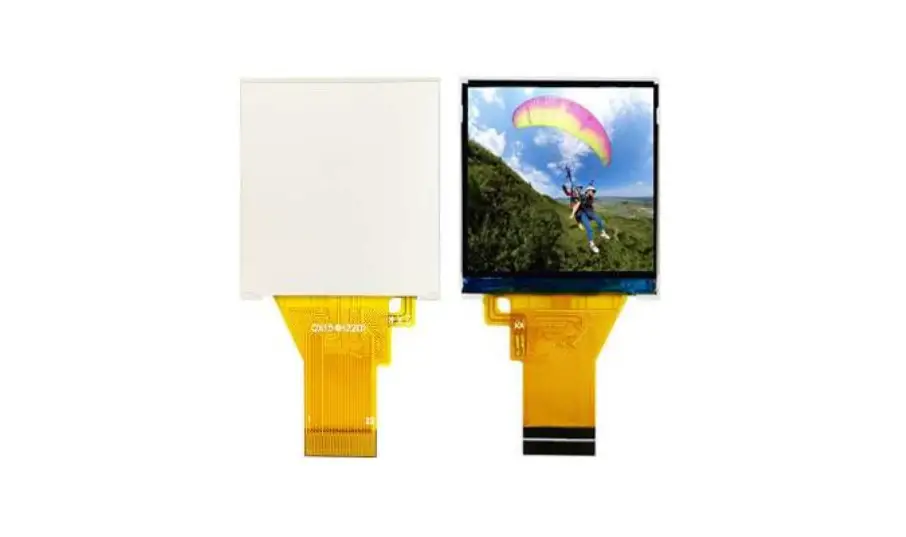
Surenoo STP0154A-240240 Series TFT LCD Panel User Manual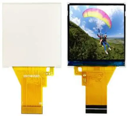
General Specifications
| No. | Item | Specification | Unit | Remark |
| 1 | LCD Size | 1.54” | inch | – |
| 2 | Panel Type | a-si TFT | – | – |
| 3 | Resolution | 240x(RGB)x240 | pixel | – |
| 4 | Display Mode | Normally Black,Transmissive | – | – |
| 5 | Display Number of Colors | 262K | – | – |
| 6 | Viewing Direction | ALL o’clock | – | Note 1 |
| 7 | Contrast Ratio | 300 | – | – |
| 8 | Luminance | 180 | cd/m2 | |
| 9 | Module Size | 31.52(W)x35.1(L)x1.72(T) | mm | Note 1 |
| 12 | Weight | TBD | g | – |
| 13 | Driver IC | ST7789V | – | – |
| 14 | Driver IC RAM Size | 240x16x240 | bit | – |
| 15 | Light Source | 3 White LED in Parallel | – | – |
| 16 | Interface | 8 Bit MCU/4L SPI Interface | – | – |
| 17 | Operating Temperature | -20~70 | ℃ | – |
| 18 | Storage Temperature | -30~80 | ℃ | – |
Note 1: Please refer to the mechanical drawing.
Mechanical Drawing
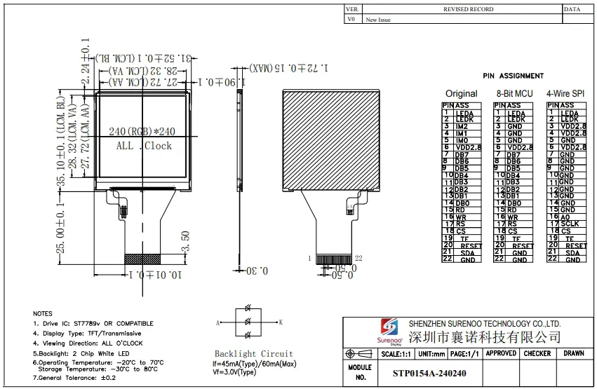
Pin Assignments
| Pin No. | Symbol | I/O | Function | Remark |
| 1 | LEDA | P | LED+ | – |
| 2 | LEDK | P | LED- | – |
| 3 | IM2 | I | – | |
| 4 | IM1 | I | – | |
| 5 | IM0 | I | – | |
| 6 | VCI(2.8V) | P | Power Supply(2.8V) | – |
| 7 | DB7 | I/O | DATA BUS | – |
| 8 | DB6 | – | ||
| 9 | DB5 | – | ||
| 10 | DB4 | – | ||
| 11 | DB3 | – | ||
| 12 | DB2 | |||
| 13 | DB1 | – | ||
| 14 | DB0 | – | ||
| 15 | RD | I | – | |
| 16 | WR | I | – | |
| 17 | RS | I | ||
| 18 | CS | I |
| |
| 19 | TE | O | Tearing effect output pin to synchronies MCU to frame rate, activated by S/W command. | |
| 20 | RESET | I | This signal will reset the device and it must be applied to properly initialize the chip. | |
| 21 | SDA | I/O | serial input/output signal in serial interface mode. | |
| 22 | GND | P | Ground |
Electrical Specifications
Absolute Maximum Rating
| Item | Symbol | Values | Unit | Remark | ||
| Min. | Max. | |||||
| TFT Module | I/O Circuit Supply Voltage | VDD | -0.3 | 4.6 | V | Note 1 |
| Analog/Logic Supply Voltage | VCI | -0.3 | 4.6 | V | Note 1 | |
| Backlight Unit | Current | IB | – | 20 | mA | Note 2 |
| Power Consumption | PBL | – | 60 | mW | Note 2 | |
Note1: Permanent damage to the device may occur if maximum values are exceeded or reverse voltage is applied.
Note2: Without LED driver IC, please refer to 1.54.
Typical Operation Conditions
DC Characteristics
| Item | Symbol | Values | Unit | Remark | ||
| Min. | Typ. | Max. | ||||
| Logic Supply Voltage | VDD | 1.65 | 2.8 | 3.3 | V | Ta=25℃ |
| Analog Supply Voltage | VCI | 2.6 | 2.8 | 3.3 | V | |
| Input High Voltage | VIH | 0.7VDD | – | VDD | V | |
| Input Low Voltage | VIL | 0 | 0.3VDD | V | ||
| Output High Voltage | VOH | 0.8VDD | – | VDD | V | |
| Output Low Voltage | VOL | 0 | – | 0.2VDD | V | |
| Frame Frequency | fFRAME | – | 65 | – | Hz | |
Note: To prevent IC latch up or DC operation in LCD panel, the power on/off sequence should follow the driver IC specification.
Current Consumption
| Item | Symbol | Values | Unit | Remark | |
| Typ. | Max. | ||||
| MCU Interfsce (8080 16-bit parallel Interface) | |||||
| Still Mode | VDD | – | TBD | uA | Note1 |
| VCI | – | TBD | mA | ||
| Sleep Mode | VDD | – | TBD | uA | Note1, Note3 |
| VCI | – | TBD | uA | ||
Note1: Test Condition
Typ:
- VDD=2.8V
- VCI=2.8V
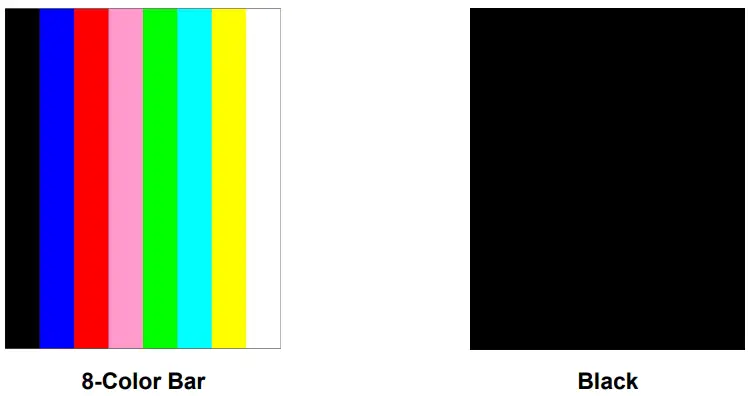
- Display Pattern: 8 Color Bar
- Frame Rate=80Hz at Line Inversion
- Operating Temperature: 25℃
- Typ. current check pattern:
Max
- VDD=3.0V
- VCI=3.3V
- Display: Pattern:All Pixel Black
- Frame Rate=80Hz at Line Inversion
- Operating Temperature: 25℃
- Max. current check pattern:
Display
Note2: In the standby mode, all the internal display operations are suspended including theinternal R-Coscillator.
Note3: In the sleep mode, all the internal display operations are suspended except the internal R-Coscillator.
Backlight Unit
The backlight system is an edge lighting type with 3white LED. (Ta=+25℃)
| Item | Symbol | Values | Unit | Remark | ||
| Min. | Typ. | Max. | ||||
| Current | IB | – | 45 | – | mA | Note 1 |
| Power Consumption | PBL | – | 135 | – | mW | Note 2 |
Note1: 3 LEDs are connected in parallel; each LED’s current consumption is 20mA.
Note2: Where IB= 45mA, PBL = IB x VBL, VBL is backlight forward voltage
Optical Specifications
(Ta=+25℃, VCI=2.8V, VDD=1.8V, IB=46mA)
| Item | Symbol | Condition | Values | Unit | Remark | ||||
| Min. | Typ. | Max. | |||||||
| Viewing Angle Range | Left | θL |
CR≧10 | - | 45 | – | degree | Note 1,2 | |
| Right | θR | - | 45 | – | |||||
| Top | θT | - | 50 | – | |||||
| Bottom | θB | - | 20 | – | |||||
| Response Time | Ton +Toff | Normal θ=Ф=0° | – | 30 | 50 | ms | Note 2,3 | ||
| Contrast Ratio | CR | Normal θ=Ф=0° | 200 | 300 | – | – | Note 2,4 | ||
| Luminance | L | Normal θ=Ф=0° | 160 | 200 | – | cd/m2 | Note 2,5 | ||
| Flicker | – | – | No Visible | – | Note 8 | ||||
| Crosstalk | – | – | No Visible | – | Note 9 | ||||
| Color Chromaticity (CIE1931) | White | Wx | Normal θ=Ф=0° | - | 0.30 | - |
– | Note 2,6 | |
| Wy | - | 0.31 | - | ||||||
| Red | Rx | 0.59 | - | ||||||
| Ry | - | 0.32 | - | ||||||
| Green | Gx | - | 0.31 | - | |||||
| Gy | - | 0.56 | - | ||||||
| Blue | Bx | - | 0.15 | - | |||||
| By | - | 0.08 | - | ||||||
| Color Gamut | NTSC | CIE1931 | – | 58 | – | % | – | ||
| Luminance Uniformity | UL | Normal θ=Ф=0° | - | 80 | – | % | Note 2,7 | ||
Note 1: Definition of viewing angle
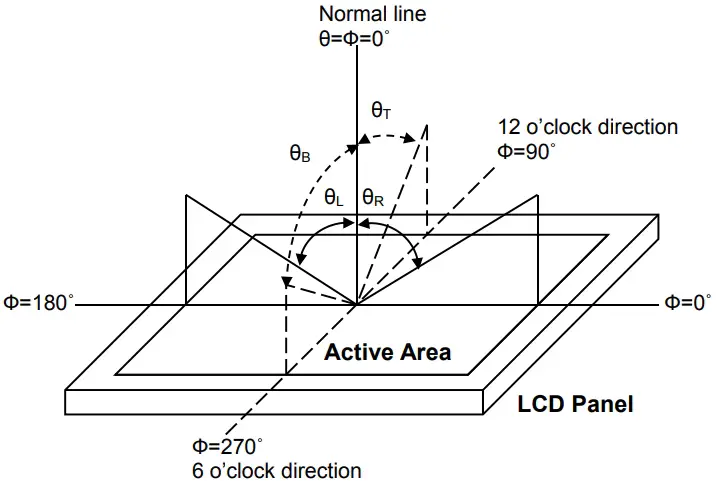
Fig. 1 Definition of viewing angle
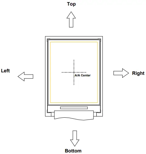
Fig. 2 Definition of viewing angle for display
Note 2: Definition of optical measurement system
The optical characteristics should be measured in a dark room with ambient temperatureTa=+25.Theoptical properties are measured at the center point of the LCD screen after 5 minutes operation. (Equipment:Photo detector TOPCON BM-5A or BM-7 /Field of view: 1˚ /Height: 500mm.)
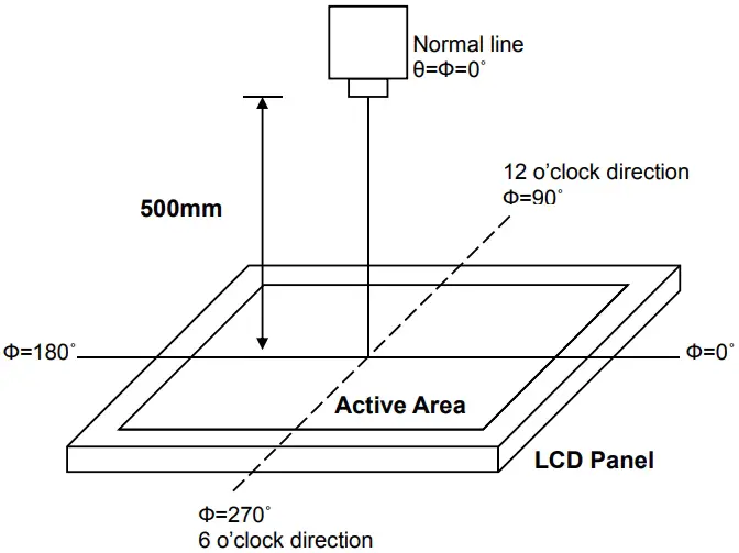
Fig. 3 Optical measurement system setup
Note 3: Definition of response time
The response time is defined as the LCD optical switching time interval between “White” stateand“Black” state. Rise time (Ton) is the time between photo detector output intensity changed from 90%to10%,and fall time (Toff) is the time between photo detector output intensity changed from 10%to 90%.
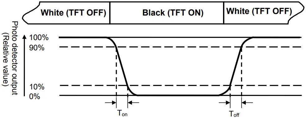
Fig. 4 Definition of response time
Note 4: Definition of contrast ratio
Contrast ratio (CR)
- Luminance measured when LCDon the” White” state
- Luminance measured when LCDon the”Black” state
Note 5: Definition of luminance
Measured at the center area of the panel when LCD panel is driven at “white” state.
Note 6: Definition of color chromaticity (CIE1931)
Color coordinates measured at the center point of LCD when panel is driven at “White”, “Red”, “Green”and “Blue” state respectively.
Note 7: Definition of luminance uniformity
To test for uniformity, the tested area is divided into 3 rows and 3 columns. The measurement spot isplacedat the center of each circle as below.
Luminance Uniformity (UL)
- Lmin
L——-Active area length W—– Active area width
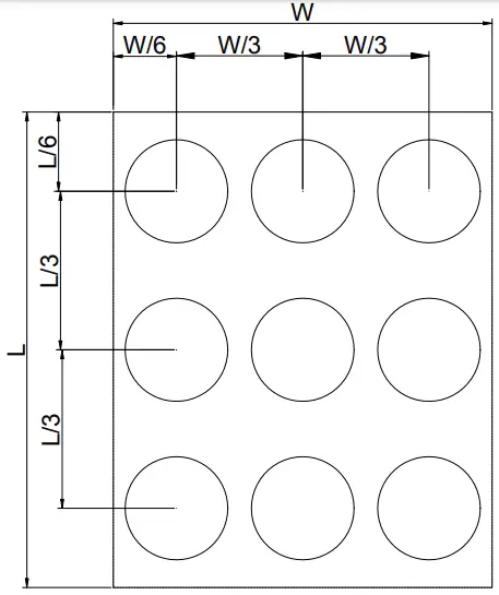
Fig. 5 Definition of luminance uniformity
Lmax : The measured maximum luminance of all measurement position.
Lmin : The measured minimum luminance of all measurement position.
Note 8: Definition of Flicker
Flicker is the pattern usually used to describe the visual sensation produced by a rapidly varying light intensity. There should be no visible flicker in normal direction of the display when the following figure are loaded.
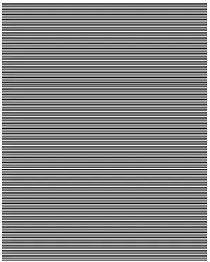
Fig.6 Flicker checker pattern
Note9: Definition of cross talk
There should be no visible in normal direction of the display when the following figures are loaded.
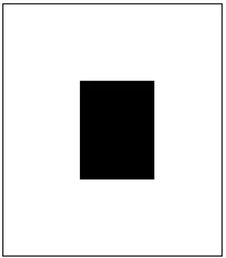
Fig.7 Crosstalk checker pattern
Reliability Test Items
| Test Items | Test Conditions | Remark |
| High Temperature Storage | +80℃±3℃ for 240 hours | – |
| Low Temperature Storage | -30℃±3℃ for 240 hours | – |
| High Temperature Operation | +70℃±3℃ for 240 hours | – |
| Low Temperature Operation | -20℃±3℃ for 240 hours | – |
| High Temperature and Humidity Operation | +60℃±3℃, 90%±3%RH max. for 240 hours | – |
| Thermal Shock | -30℃/0.5h ~ +80℃/0.5h for a total 100 cycles, Start with cold temp and end with high temp | – |
| Vibration Test | Frequency range:10~55Hz Stoke: 1.5mm Sweep: 10Hz~55Hz~10Hz 2 hours for each direction of X. Y. Z. (6 hours for total) | – |
| Mechanical Shock | 100G 6ms,±X, ±Y, ±Z 3 times for each direction | – |
| Package Vibration Test | Random Vibration : 0.015G2/Hz from 5-200Hz, -6dB/Octave from 200-500Hz 1 hour for each direction of X. Y. Z. (3 hours for total) | – |
| Package Drop Test | Height :76cm(Weight≦10kg); 60cm(Weight>10kg) 1 corner, 3 edges, 6 surfaces | – |
| Electro Static Discharge | ± 2KV, Human Body Mode, 100pF/1500Ω | – |
Note1: During the display practical test under normal operation condition, there shall be no change, which may affect display function.
Note2: Before functional check, the test sample requires a 2 hours storage time at room temperature.
Handling Precautions
Safety
The liquid crystal in the LCD is poisonous. DO NOT put it in your mouth. If the liquid crystal touches your skin or clothes, wash it off immediately using soap and water
Handling
- The LCD and touch panel is made of plate glass. DO NOT subject the panel to mechanical shock or to excessive force on its surface.
- Do not handle the product by holding the flexible pattern portion in order to assure the reliability
- Transparency is an important factor for the touch panel. Please wear clear finger sacks, gloves and mask to protect the touch panel from finger print or stain and also hold the portion outside the view area when handling the touch panel.
- Provide a space so that the panel does not come into contact with other components.
- To protect the product from external force, put a covering lens (acrylic board or similar board) and keep an appropriate gap between them.
- Transparent electrodes may be disconnected if the panel is used under environmental conditions where dew condensation occurs.
- Property of semiconductor devices may be affected when they are exposed to light, possibly resulting in IC malfunctions.
- To prevent such IC malfunctions, your design and mounting layout shall bed one in the way that the IC is not exposed to light in actual use.
Static Electricity
- Ground soldering iron tips, tools and testers when they are in operation.
- Ground your body when handling the products.
- Power on the LCD module BEFORE applying the voltage to the input terminals.
- DO NOT apply voltage which exceeds the absolute maximum rating.
- Store the products in an anti-electrostatic bag or container.
Storage
- Store the products in a dark place at +25℃±10℃ with low humidity (65%RHor less).
- DO NOT store the products in an atmosphere containing organic solvents or corrosive gas.
Cleaning
- DO NOT wipe the touch panel with dry cloth, as it may cause scratch.
- Wipe off the stain on the product by using soft cloth moistened with ethanol. DO Not allow ethanol to get in between the upper film and the bottom glass. It may cause peeling issue or defective operation. Do not use any organic solvent or
detergent other than ethanol.


