Contents hide
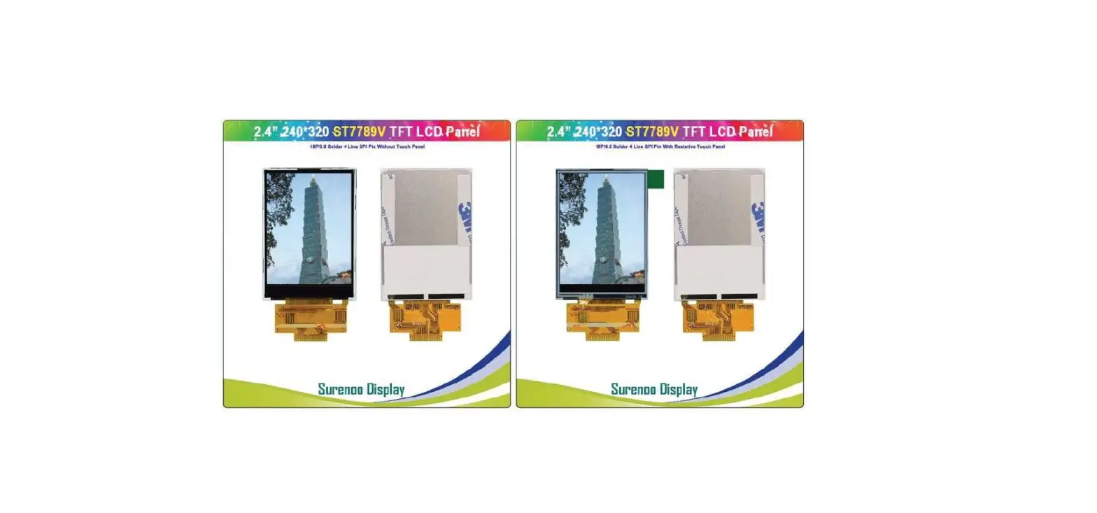
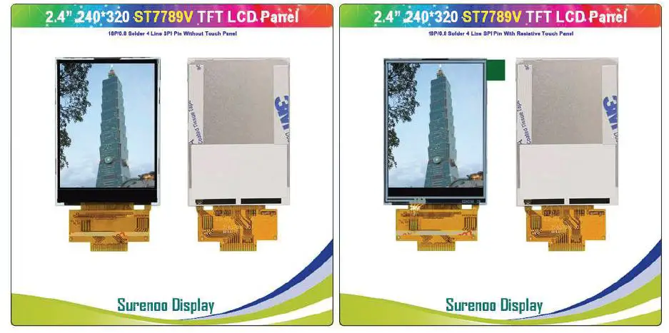
 Surenoo STP0240A2-240320 Series TFT LCD Panel
General Description
| MODEL NO | STP0240A2-240320 (YT240S010) |
| Display Mode | Transmissive |
| Display Format | Graphic 240RGB*320 Dot-matrix 240xRGBx320 |
| Input Data | 4 Line-SPI interface 4 |
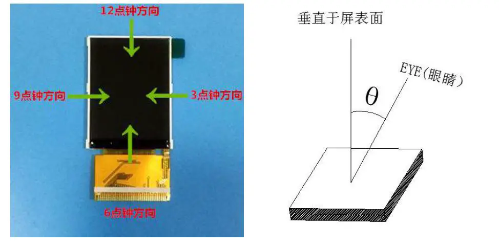
| Viewing Direction | 12 o’clock 12 |
| Drive | ST7789V |
Mechanical Specification
| Item | Specifications | Unit |
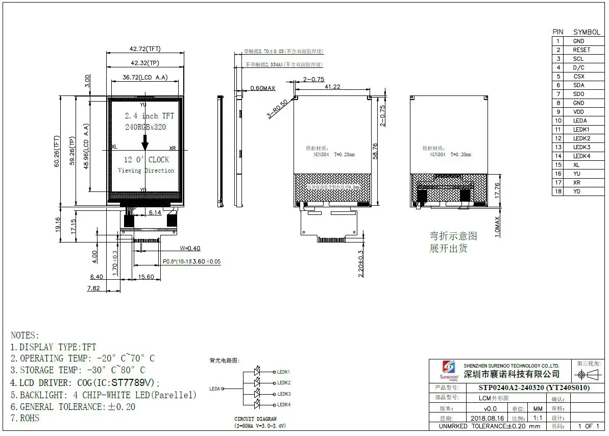
| Dimensional outline | 42.72(W)*60.26(H)*2.55(T)(NTP) 42.72(W)*60.26(H)*3.75(T)(RTP) (FPC not include) | mm |
| Resolution | 240RGB*320 | dots |
| LCD Active area | 36.72(W)*48.96 (H) | mm |
| Pixel size | 0.153(W)*0.153(H) | mm |
Mechanical Dimension
Electrical Maximum Ratings
| Item | Symbol | Min | Max | Unit | Note |
| Supply voltage(VDDI) | V | 1.8 | 3.3 | V | – |
| Supply voltage(VDD) | V | 2.8 | 3.3 | V | – |
| Operating temperatur | TOPR | -20 | 70 | ℃ | – |
| Storage temperature | TSTR | -30 | 80 | ℃ | – |
Brightness characteristic&Power dissipation
| Item | Symbol | Min | Typical | Max | Unit |
| LED module Forward voltage | VLED | 2.9 | 3.1 | 3.3 | V |
| LED module current | ILED | – | 60 | – | mA |
| LCD Surface Luminance | LS | 250 | 300 | – | Cd/m2 |
| LCM Surface brightness uniform | LD | 80 | – | – | % |
| LCD power dissipation | PLCD | – | 0.22 | – | W |
Module Function Description
| PIN No. | Symbol | Description | Notes |
| 1 | GND | Ground | – |
| 2 | RESET | -This signal will reset the device and it must be applied to properly initialize the chip. -Signal is active low. | – |
| 3 | SCL | -This pin is used to be serial interface clock. | – |
| 4 | D/C | – Display data/command selection pin in 4-line serial interface. | – |
| 5 | CSX | -Chip selection pin Low enable. High disable. | – |
| 6 | SDA | SPI interface input pin. -The data is latched on the rising edge of the SCL signal. -If not used, please fix this pin at VDDI or DGND level. | – |
| 7 | SDO | -SPI interface output pin. -The data is output on the falling edge of the SCL signal. -If not used, let this pin open. | – |
| 8 | GND | Ground | – |
| 9 | VDD | Power Supply for Analog, Digital System and Booster Circuit. | – |
| 10 | LEDA | Anode of Backlight (2.9V-3.3V Typical:3.1V) | – |
| 11 | LEDK1 | Cathode of Backlight | – |
| 12 | LEDK2 | Cathode of Backlight | – |
| 13 | LEDK3 | Cathode of Backlight | – |
| 14 | LEDK4 | Cathode of Backlight | – |
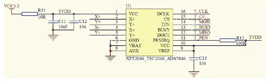
| 15 | XL | Touch panel Logical foot | – |
| 16 | YU | Touch panel Logical foot | – |
| 17 | XR | Touch panel Logical foot | – |
| 18 | YD | Touch panel Logical foot | – |
STP0240A2 4
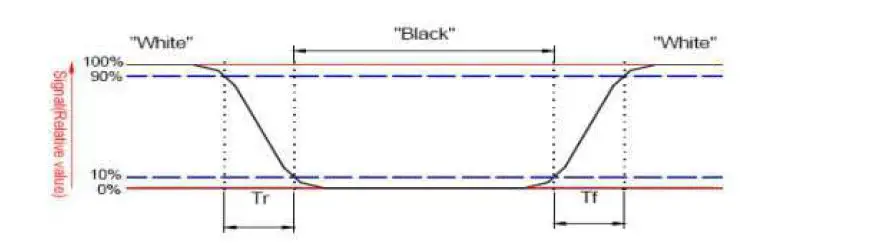
Response time&Contrast ratio
| Item | Symbol | Condition | Remark | Unit | ||
| Min. | Typ. | Max. | ||||
| Response time | Tr+Tf | θ=0° | – | 25 | 40 | ms |
| Contrast ratio | CR | θ=0° | 350 | 500 | – | – |
Viewing Angle
| Item | Symbol | Condition | Remark | Unit | ||
| Min. | Typ. | Max. | ||||
|
Viewing angle | Top 12 | CR≥10 10 | 40 | 50 | – |
Deg.
|
| Bottom 6 | CR≥10 10 | 55 | 65 | – | ||
| Left 9 | CR≥10 10 | 55 | 65 | – | ||
| Right 3 | CR≥10 10 | 55 | 65 | – | ||
Reliability Trial
| NO. | ITEM | CONDITION | CRITERION |
| 1 | High Temperature Non-Operating Test | 80℃*120Hrs | No Defect Of Operational Function In Room Temperature Are Allowable |
| 2 | Low Temperature Non-Operating Test | -30℃*120Hrs | |
| 3 | High Temperature/Humidity Non Operating Test | 60℃*90%RH*120Hrs | |
| 4 | High Temperature Operating Test | 70℃*72Hrs | |
| 5 | Low Temperature Operating Test | -20℃*72Hrs | |
| 6 | Thermal Shock Test | -20 ℃ (30Min) Q70 ℃ (30Min) *10CYCLES |
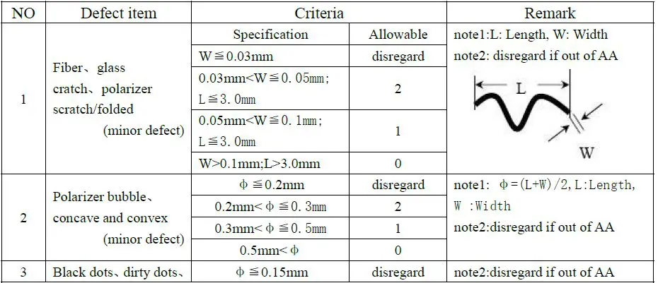
Inspection standards
Glass defect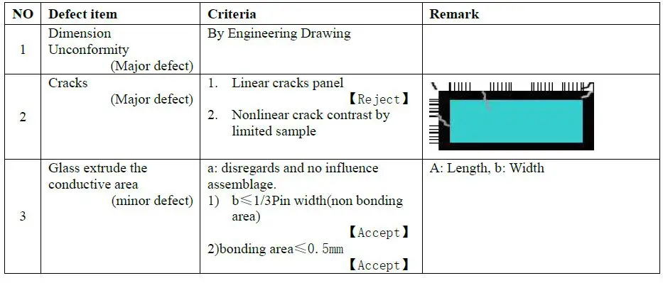
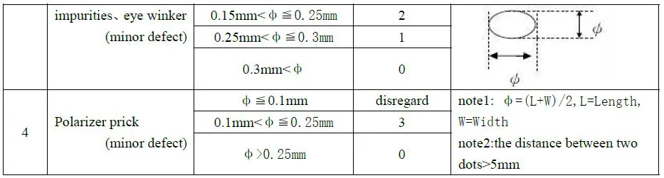
 LCD appearance defect(View area)
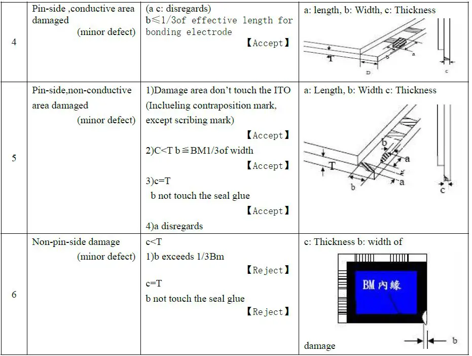