
![]() 150W Constant Power Mode LED Driver
150W Constant Power Mode LED Driver
XLG-150 series
 http://www.meanwell.com.cn/Upload/PDF/LED_EN.pdf
![]()
![]()
Features
- Widenputange00~305VC(lass)
- Fullowerutputt0~100%onstantowerodeperation
- MetalaseithP67,uitableorutdoorpplication
- SurgerotectionithKV/4KV10KV/6KVptional)
- 3nimmingunctionDimoffndsolationesign)
- IndiaEESL)ersionithnputveroltagerotectioncan
urvivenputoltagetressf40Vacor8ours - Protectionunctions:VP/SCP/OCP/OTP
- Lifeime50,000rs.ndearsarranty
Applications
- Skyscraperighting
- Streetighting
- Floodlightighting
- Stageighting
- Fishingighting
- Horticultureighting
- Lighting
- DMXpowersupply
- TypeLorsenlass,ivision
Description
XLG-150 series is a 150W LED AC/DC driver featuring the constant power mode.XLG-150 operates from 100-305VAC and offers models with different rated currents ranging between 700mA and 12500mA. Thanks to the high efficiency of up to 93%, with the fanless design, the entire series is able to operate for -40 C -+90 C case temperature under free air convection. The design of metal housing and IP67 ingress protection level allows this series to fit both indoor and outdoor applications. Moreover, the innovative environment-adaptive capability allows this series to reliably light on the LEDs for all kinds of application environments in almost any spot that may install LED luminaires in the world. XLG-150 series comply with the latest version of IEC61347/GB7000.1-2015 and UL8750 international safety regulations. The output and dimming circuit are also completely in accordance with the new regulations with isolation to ensure the safety of both the user and luminaire system during installation.
Modelncoding
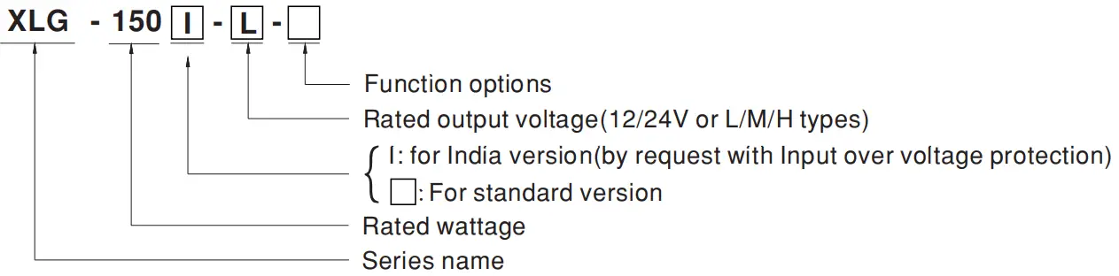
| Type | Function | Note |
| Blank | lo and Vo fixed.(For harsh environments) | By request |
| A | lo adjustable via built-in potentiometer | In Stock |
| AB | lo adjustable via built-in potentiometer + 3 in 1 dimming function (0-10Vdc, 10V PWM signal and resistance) | In Stock |
Note:.12Vnd4VodelsithoutheABype
2.IndiaersioneedsOQorroduction,leaseonsultEANWELLoretail
SPECIFICATION
MODEL | XLG-150 -12- | XLG-150 -24- | |||
| OUTPUT | DC VOLTAGE | 12V | 24V | ||
| CONSTANT CURRENT REGION Note.2 | 8.4~ 12V | 16.8~ 24V | |||
| RATED CURRENT | 12.5A | 6.25A | |||
| RATED POWER | 150W | 150W | |||
| RIPPLE & NOISE (max.) Note.3 | 150mVp-p | 240mVp-p | |||
| CURRENT ADJ. RANGE | Adjustable for A-Type only (via the built-in potentiometer) | ||||
| 6.5~ 12.5A | 3.2~ 6.25A | ||||
| VOLTAGE TOLERANCE Note.4 | ±3.0% | ±2.0% | |||
| LINE REGULATION | ±0.5% | ±0.5% | |||
| LOAD REGULATION | ±2% | ±1% | |||
| SETUP, RISE TIME Note.6 | 500ms, 100ms/230VAC, 1200ms, 100ms/115VAC | ||||
| HOLD UP TIME (Typ.) | 10ms/ 230VAC 10ms/ 115VAC | ||||
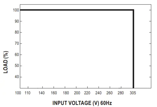
| INPUT | VOLTAGE RANGE Note.5 | 100 ~ 305VAC 142 ~ 431VDC (Please refer to the “STATIC CHARACTERISTIC” section) | |||
| FREQUENCY RANGE | 47 ~ 63Hz | ||||
| POWER FACTOR | PF≧0.97/115VAC, PF≧0.95/230VAC, PF≧0.92/277VAC@full load | ||||
| TOTAL HARMONIC DISTORTION | THD< 10%(@load≧50%/115VC,230VAC; @load≧75%/277VAC) | ||||
| EFFICIENCY (Typ.) | 91.5% | 93% | |||
| AC CURRENT | 1.8A / 115VAC 1.0A / 230VAC 0.8A/277VAC | ||||
| INRUSH CURRENT(Typ.) | COLD START 50A(twidth=500μs measured at 50% Speak) at 230VAC; Per NEMA 410 | ||||
| MAX. No. of PSUs on 16A CIRCUIT BREAKER | 4 units (circuit breaker of type B) / 8 units (circuit breaker of type C) at 230VAC | ||||
| LEAKAGE CURRENT | <0.75mA / 277VAC | ||||
| NO LOAD POWER CONSUMPTION | No load power consumption <0.5W(for standard version) | ||||
| PROTECTION | OVER CURRENT | 95 ~ 108% | |||
| Hiccup mode or constant current limiting recovers automatically after the fault condition is removed | |||||
| SHORT CIRCUIT | Hiccup mode or constant current limiting recovers automatically after the fault condition is removed | ||||
| OVERVOLTAGE | 13.5 ~ 18V | 27 ~ 34V | |||
| Shut down output voltage, and re-power on to recover | |||||
| INPUT OVER VOLTAGE Note.7 | 320 ~ 390VAC (Shut down output voltage when the input voltage exceeds protection voltage, recovers automatically after fault condition is removed) | ||||
| Can survive input voltage stress of 440Vac for 48 hours @ tc 75℃ max | |||||
| OVER TEMPERATURE | Shut down output voltage, and re-power on to recover | ||||
| ENVIRONMENT | WORKING TEMP. | Tcase=-40 ~ +90℃ (Please refer to “ OUTPUT LOAD vs TEMPERATURE” section) | |||
| MAX. CASE TEMP. | Tcase=+90℃ | ||||
| WORKING HUMIDITY | 20 ~ 95% RH non-condensing | ||||
| STORAGE TEMP., HUMIDITY | -40 ~ +90℃, 10 ~ 95% RH | ||||
| TEMP.COEFFICIENT | ±0.06%/℃ (0 ~ 60℃) | ||||
| VIBRATION | 10 ~ 500Hz, 5G 12min./1cycle, the period for 72min. each along the X, Y, and Z axes | ||||
| SAFETY & EMC | SAFETY STANDARDS Note.7 | UL8750(type”HL”), UL879,CSA C22.2 No. 250.13-12; ENEC BS EN/EN61347-1, BS EN/EN61347-2-13 independent, BS EN/EN62384; GB19510.1,GB19510.14;EAC TP TC 004; J61347-1(H29), J61347-2-13(H29),KC61347-1,KC61347-2-13,IS15885(Part2/Sec13) (for XLG-150I type only); NOM-058-SCFI-2017(except for Blank type); IP67 approved | |||
| WITHSTAND VOLTAGE | I/P-O/P:3.75KVAC I/P-FG:2KVAC O/P-FG:1.5KVAC | ||||
| ISOLATION RESISTANCE | I/P-O/P, I/P-FG, O/P-FG:100M Ohms / 500VDC / 25℃/ 70% RH | ||||
| EMC EMISSION | Parameter | Standard | Test Level/Note | ||
| Conducted | BSEN/EN55015(CISPR15) ,GB/T17743 | —– | |||
| Radiated | BSEN/EN55015(CISPR15) ,GB/T17743 | —– | |||
| Harmonic Current | BS EN/EN61000-3-2 ,GB/T17625.1 | Class C @load≥50% | |||
| Voltage Flicker | BS EN/EN61000-3-3 | —– | |||
| EMC IMMUNITY | BS EN/EN61547 | ||||
| Parameter | Standard | Test Level/Note | |||
| ESD | BS EN/EN61000-4-2 | Level 3, 8KV air ; Level 2, 4KV contact | |||
| Radiated | BS EN/EN61000-4-3 | Level 2 | |||
| EFT/Burst | BS EN/EN61000-4-4 | Level 3 | |||
| Surge | BS EN/EN61000-4-5 | 4KV/Line-Line 6KV/Line-Earth(6K/10K option) | |||
| Conducted | BS EN/EN61000-4-6 | Level 2 | |||
| Magnetic Field | BS EN/EN61000-4-8 | Level 4 | |||
| Voltage Dips and Interruptions | BS EN/EN61000-4-11 | >95% dip 0.5 periods, 30% dip 25 periods,>95% interruptions 250 periods | |||
| OTHERS | MTBF | 712.17K hrs min. Telcordia SR-332 (Bellcore) ; 213.3Khrs min. MIL-HDBK-217F (25℃) | |||
| DIMENSION | 180*63*35.5mm (L*W*H) | ||||
| PACKING | 0.8Kg;16pcs / 13.4Kg /0.67CUFT | ||||
| NOTE | 1. All parameters NOT specially mentioned are measured at 230VAC input, rated current, and 25℃ of ambient temperature. 2. Please refer to “DRIVING METHODS OF LED MODULE”. 3. Ripple & noise are measured at 20MHz of bandwidth by using a 12″ twisted pair-wire terminated with a 0.1uf & 47uf parallel capacitor. 4. Tolerance: includes set up tolerance, line regulation, and load regulation. 5. De-rating may be needed under low input voltages. Please refer to the “STATIC CHARACTERISTIC” sections for details. 6. Length of set up time is measured at first cold start. Turning ON/OFF the driver may lead to an increase in the set-up time. 7. Input over-voltage only for XLG-150 I series, and I series without UL/CSA certificate. 8. The driver is considered a component that will be operated in combination with the final equipment. Since EMC performance will be affected by the complete installation, the final equipment manufacturers must re-qualify EMC Directive on the complete installation again. 9. The ambient temperature derating of 3.5℃/1000m with fanless models and of 5℃/1000m with fan models for operating altitudes higher than 2000m(6500ft). 10. Please refer to the warranty statement on MEAN WELL’s website at http://www.meanwell.com 11. This series meets the typical life expectancy of >50,000 hours of operation when Tcase, particularly tc point (or TMP, per DLC), is about 75℃ or less. 12. Products sourced from the Americas regions may not have the CCC/PSE/BIS/KC logo. Please contact your MEAN WELL sales for more information. 13. For any application note and IP waterproof function installation caution, please refer to our user manual before using. https://www.meanwell.com/Upload/PDF/LED_EN.pdf 14. To fulfill the requirements of the latest ErP regulation for lighting fixtures, this LED driver can only be used behind a switch without being permanently connected to the mains. 15. If you need the NOM (Mexico) certificate, Please contact the MEAN WELL sales representative for details. ※ Product Liability Disclaimer: For detailed information, please refer to https://www.meanwell.com/serviceDisclaimer.aspx File Name: XLG-150-SPEC 2021-11-26 | ||||
| MODEL | XLG-150 -L- | XLG-150 | -M- | XLG-150 | -H- | ||||
| OUTPUT | RATED CURRENT | 700mA | 1400mA | 2800mA | |||||
| RATED POWER | 150W | 150W | 150W | ||||||
| CONSTANT CURRENT REGION | 120 ~214V | 60 ~ 107V | 27 ~ 56V | ||||||
| FULL POWER CURRENT RANGE | 700~1050mA | 1400~2100mA | 2680~4170mA | ||||||
| OPEN CIRCUIT VOLTAGE (max.) | 225V | 115V | 60V | ||||||
| CURRENT ADJ. RANGE | Adjustable for A/AB-Type only (via the built-in potentiometer) | ||||||||
| 350~1050mA | 700~2100mA | 1400~4170mA | |||||||
| CURRENT RIPPLE | 4.0%(@ full load) | 3.0%(@ full load) | 3.0%(@ full load) | ||||||
| CURRENT TOLERANCE | ±5% | ||||||||
| SET UP TIME | 500ms/230VAC, 1200ms/115VAC | ||||||||
| INPUT | VOLTAGE RANGE | Note.5 | 100 ~ 305VAC 142VDC ~ 431VDC(Please refer to “STATIC CHARACTERISTIC” and “ DRIVING METHODS OF LED MODULE” sections) | ||||||
| FREQUENCY RANGE | 47 ~ 63Hz | ||||||||
| POWER FACTOR (Typ.) | PF≧0.97 / 115VAC, PF≧0.95 / 230VAC, PF≧0.92 / 277VAC at full load(Please refer to “Power Factor Characteristic” section) | ||||||||
| TOTAL HARMONIC DISTORTION | THD< 10% (@ load≧50% at 115VAC/230VAC ,@load≧75% at 277VAC) Please refer to “TOTAL HARMONIC DISTORTION (THD)” section | ||||||||
| EFFICIENCY (Typ.) | 93% | 92.5% | 92% | ||||||
| AC CURRENT (Typ.) | 1.8A / 115VAC 1.0A / 230VAC 0.8A/277VAC | ||||||||
| INRUSH CURRENT(Typ.) | COLD START50A(twidth=500μs measured at 50% Speak) at 230VAC; Per NEMA 410 | ||||||||
| MAX. NO. of PSUs on 16A CIRCUIT BREAKER | 4 units (circuit breaker of type B) / 8 units(circuit breaker of type C) at 230VAC | ||||||||
| LEAKAGE CURRENT | <0.75mA / 277VAC | ||||||||
| STANDBY POWER CONSUMPTION | Note.14 | Standby power consumption <0.5W for AB-Type(Dimming OFF)(for standard version) | |||||||
| PROTECTION | SHORT CIRCUIT | Hiccup mode or Constant current limiting recovers automatically after the fault condition is removed | |||||||
| OVERVOLTAGE | 230 ~ 265V | 128~ 150V | 61 ~ 85V | ||||||
| Shut down output voltage, re-power on to recovery | |||||||||
| INPUT OVER VOLTAGE Note.7 | 320 ~ 390VAC (Shut down output voltage when the input voltage exceeds protection voltage, recovers automatically after fault condition is removed) | ||||||||
| Can survive input voltage stress of 440Vac for 48 hours @ tc 75℃ max | |||||||||
| OVER TEMPERATURE | Shut down output voltage, and re-power on to recover | ||||||||
| ENVIRONMENT | WORKING TEMP. | Tcase=-40 ~ +90℃(Please refer to “OUTPUT LOAD vs TEMPERATURE” section) | |||||||
| MAX. CASE TEMP. | Tcase=+90℃ | ||||||||
| WORKING HUMIDITY | 20 ~ 95% RH non-condensing | ||||||||
| STORAGE TEMP., HUMIDITY | -40 ~ +80℃, 10 ~ 95% RH non-condensing | ||||||||
| TEMP. COEFFICIENT | ±0.06%/℃ (0 ~ 60℃) | ||||||||
| VIBRATION | 10 ~ 500Hz, 5G 12min./1cycle, the period for 72min. each along the X, Y, and Z axes | ||||||||
| SAFETY & EMC | SAFETY STANDARDS Note.7 | UL8750(type”HL”), CSA C22.2 No. 250.13-12; ENEC BS EN/EN61347-1, BS EN/EN61347-2-13 independent, BS EN/EN62384; GB19510.1,GB19510.14;EAC TP TC 004;J61347-1(H29), J61347-2-13(H29),KC61347-1,KC61347-2-13, IS15885(Part2/Sec13) (for XLG-150I type only); NOM-058-SCFI-2017(except for Blank type); IP67 approved | |||||||
| WITHSTAND VOLTAGE | I/P-O/P:3.75KVAC I/P-FG:2KVAC O/P-FG:1.5KVAC | ||||||||
| ISOLATION RESISTANCE | I/P-O/P, I/P-FG, O/P-FG:100M Ohms / 500VDC / 25℃/ 70% RH | ||||||||
| EMC EMISSION | Parameter | Standard | Test Level/Note | ||||||
| Conducted | BSEN/EN55015(CISPR15) ,GB/T17743 | —– | |||||||
| Radiated | BSEN/EN55015(CISPR15) ,GB/T17743 | —– | |||||||
| Harmonic Current | BS EN/EN61000-3-2 ,GB/T17625.1 | Class C @load≥50% | |||||||
| Voltage Flicker | BS EN/EN61000-3-3 | —– | |||||||
| EMC IMMUNITY | BS EN/EN61547 | ||||||||
| Parameter | Standard | Test Level/Note | |||||||
| ESD | BS EN/EN61000-4-2 | Level 3, 8KV air ; Level 2, 4KV contact | |||||||
| Radiated | BS EN/EN61000-4-3 | Level 2 | |||||||
| EFT/Burst | BS EN/EN61000-4-4 | Level 3 | |||||||
| Surge | BS EN/EN61000-4-5 | 4KV/Line-Line 6KV/Line-Earth(6K/10K option) | |||||||
| Conducted | BS EN/EN61000-4-6 | Level 2 | |||||||
| Magnetic Field | BS EN/EN61000-4-8 | Level 4 | |||||||
| Voltage Dips and Interruptions | BS EN/EN61000-4-11 | >95% dip 0.5 periods, 30% dip25periods,>95%interruptions 250 periods | |||||||
| OTHERS | MTBF | 712.17K hrs min. Telcordia SR-332 (Bellcore) ; | 213.3Khrs min. | MIL-HDBK-217F (25℃) | |||||
| LIFETIME Note.4 | 50000 hrs min. | ||||||||
| DIMENSION | 180*63*35.5mm (L*W*H) | ||||||||
| PACKING | 0.8Kg;16pcs/13.4Kg/0.67CUFT | ||||||||
| NOTE | 1. All parameters NOT specially mentioned are measured at 230VAC input, rated current, and 25℃ of ambient temperature. 2. Please refer to “DRIVING METHODS OF LED MODULE”. 3. Ripple & noise are measured at 20MHz of bandwidth by using a 12″ twisted pair-wire terminated with a 0.1uf & 47uf parallel capacitor. 4. Tolerance: includes set up tolerance, line regulation, and load regulation. 5. De-rating may be needed under low input voltages. Please refer to the “STATIC CHARACTERISTIC” sections for details. 6. Length of set up time is measured at first cold start. Turning ON/OFF the driver may lead to an increase in the set-up time. 7. Input over-voltage only for XLG-150 I series, and I series without UL/CSA certificate. 8. The driver is considered a component that will be operated in combination with the final equipment. Since EMC performance will be affected by the complete installation, the final equipment manufacturers must re-qualify EMC Directive on the complete installation again. 9. The ambient temperature derating of 3.5℃/1000m with fanless models and of 5℃/1000m with fan models for operating altitudes higher than 2000m(6500ft). 10. Please refer to the warranty statement on MEAN WELL’s website at http://www.meanwell.com 11. This series meets the typical life expectancy of >50,000 hours of operation when Tcase, particularly tc point (or TMP, per DLC), is about 75℃ or less. 12. Products sourced from the Americas regions may not have the CCC/PSE/BIS/KC logo. Please contact your MEAN WELL sales for more information. 13. For any application note and IP waterproof function installation caution, please refer to our user manual before using. https://www.meanwell.com/Upload/PDF/LED_EN.pdf 14. To fulfill the requirements of the latest ErP regulation for lighting fixtures, this LED driver can only be used behind a switch without being permanently connected to the mains. 15. If you need the NOM (Mexico) certificate, Please contact the MEAN WELL sales representative for details. ※ Product Liability Disclaimer: For detailed information, please refer to https://www.meanwell.com/serviceDisclaimer.aspx File Name: XLG-150-SPEC 2021-11-26 | ||||||||
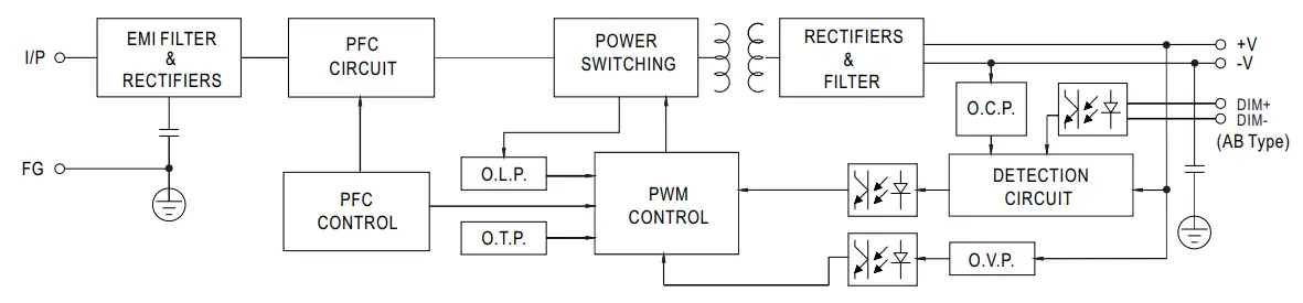
BLOCK DIAGRAM
PFC fosc: 50~120KHz
PWM for: 60~130KHz
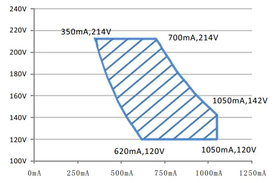
DRIVING METHODS OF LED MODULE
※ I-V Operating Area
XLG-150-L
![]() Recommend Performance Region
Recommend Performance Region
XLG-150-H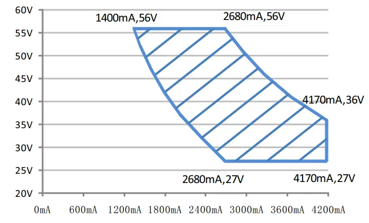
![]() Recommend Performance Region
Recommend Performance Region
XLG-150-M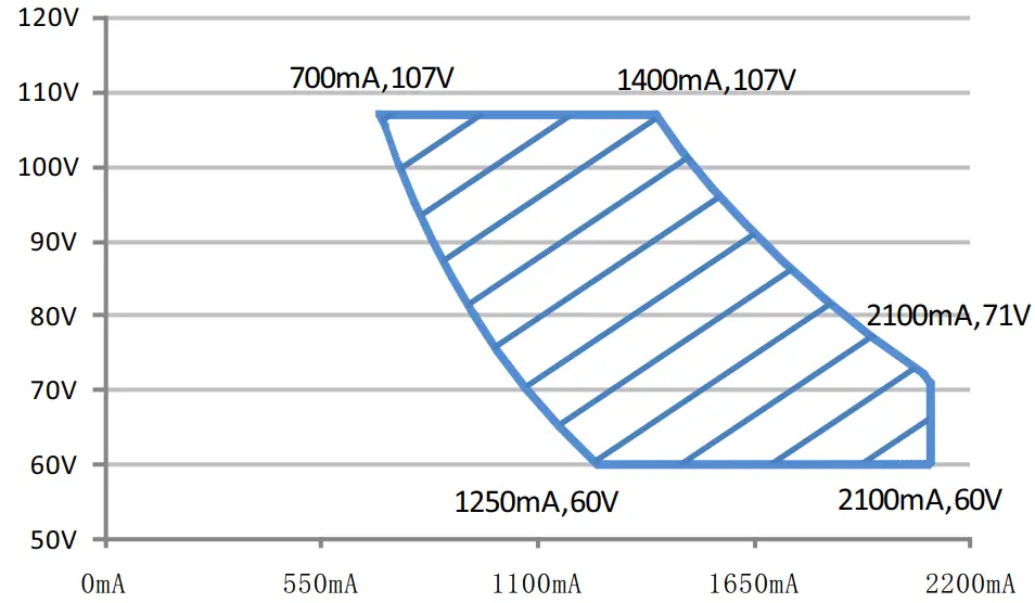
![]() Recommend Performance Region
Recommend Performance Region
XLG-150-12,24
※ This series is able to work in either Constant Current mode (a direct drive way) or Constant Voltage mode (usually through additional DC/DC driver) to drive the LEDs.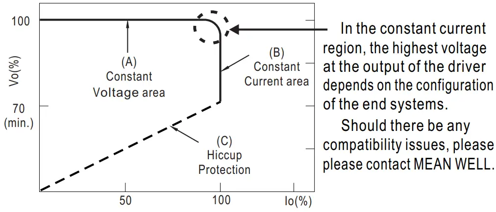 Typical output current normalized by rated current (%)
In the constant current region, the highest voltage at the output of the driver depends on the configuration of the end systems. Should there be any
compatibility issues, please please contact MEAN WELL.
DIMMING OPERATION
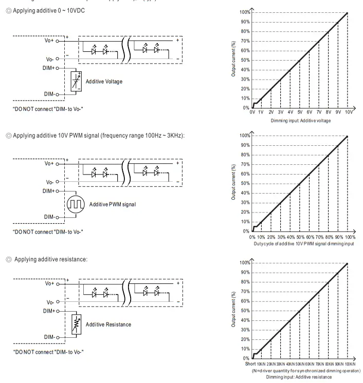
※ 3 in 1 dimming function (for AB-Type)
- Output constant current level can be adjusted by applying one of the three methodologies between DIM+ and DIM-:
0 ~ 10VDC, or 10V PWM signal or resistance. - Direct connecting to LEDs is suggested. It is not suitable to be used with additional drivers.
- Dimming source current from power supply: 100 A (typ.)μ
Note :
- Min. dimming level is about 8% and the output current is not defined when 0%< Iout<8%.
- The output current could drop down to 0% when the dimming input is about 0kΩ or 0Vdc, or 10V PWM signal with 0% duty cycle.
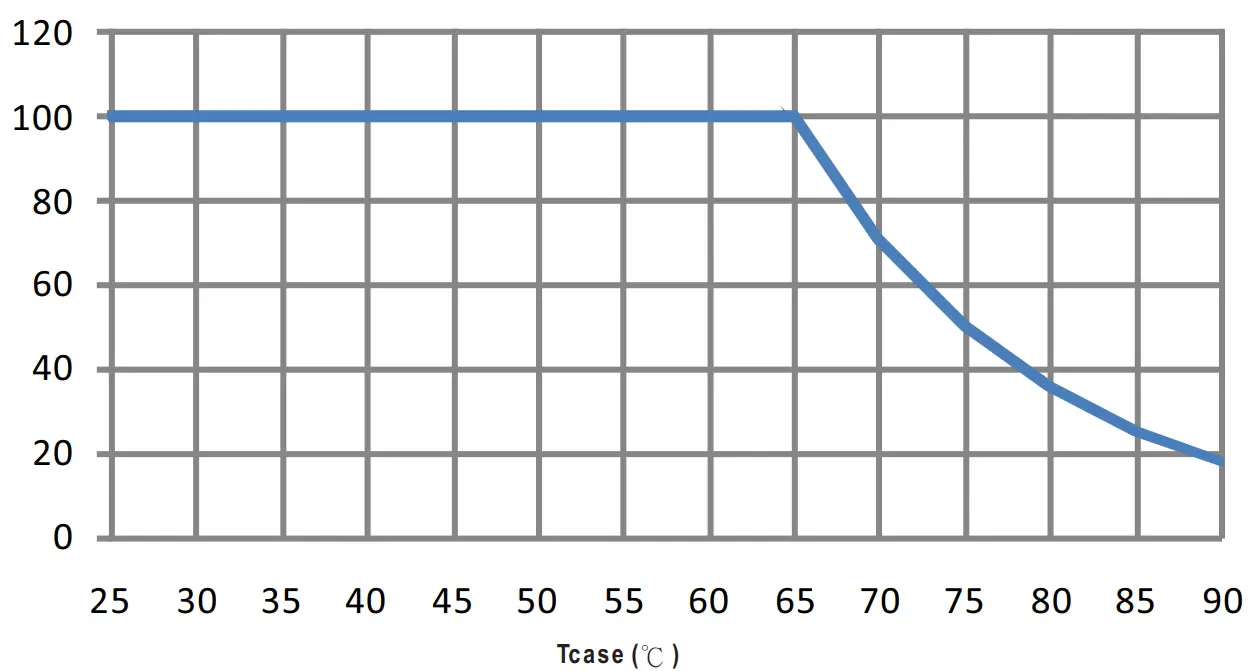
OUTPUT LOAD vs TEMPERATURE
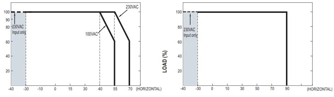 AMBIENT TEMPERATURE RA C• Tcse •c
If XLG-150 operates in Constant Current mode with the rated
current the maximum workable Ta is 55℃ (Typ. 230VAC) or 40℃ (Typ.100Below 110VAC@ -30℃may retry to 2nd setup
STATIC CHARACTERISTIC
TOTAL HARMONIC DISTORTION (THD)
XLG-150-L Model, Tcase at 75℃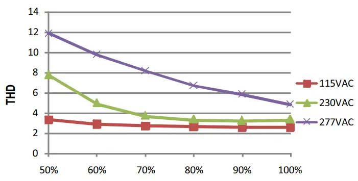
OWER FACTOR (PF) CHARACTERISTIC
Tcase at 75℃
Constant Current Mode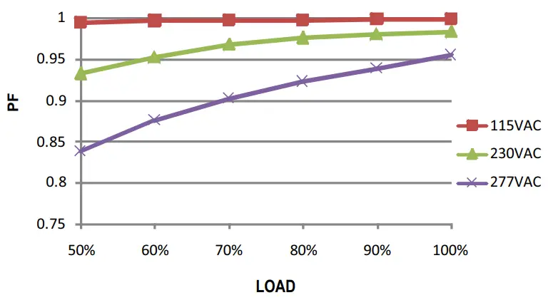
EFFICIENCY vs LOAD
XLG-150 series possess superior working efficiency that up to 93% can be reached in field applications.
XLG-150-L Model, Tcase at 75 ℃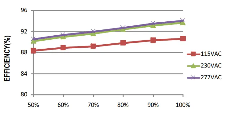
LIFE TIME
MECHANICAL SPECIFICATION
※ Blank-Type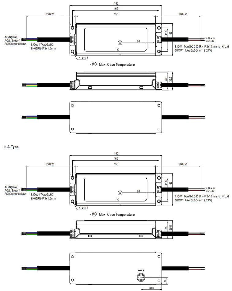
※ AB-Type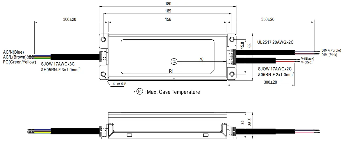
INSTALLATION MANUAL
Please refer to http://www.meanwell.comimanual.html


