![]() XLG-100 100W Constant
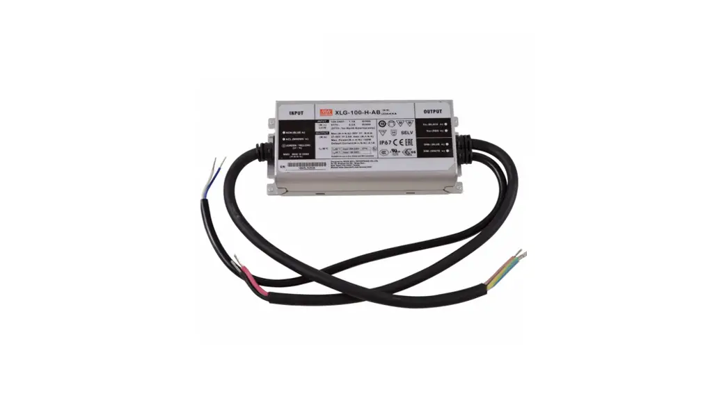
XLG-100 100W Constant
Power Mode LED Driver
Instruction Manual


 http://www.meanwell.com.cn/Upload/PDF/LED_EN.pdf
Features
- Wide input range 100-305VAC( Class I )
- Full power output at 70-100% Constant power mode operation
- Metal case with IP67, suitable for outdoor application
- LVLE(H type),Class 2(24V)power unit
- Surge protection with 6KV/4KV (10KV/6KV optional)
- 3 in 1 dimming function (Dim to off and Isolation design)
- India (EESL) version with Input Over Voltage Protection can survive input voltage stress of 440Vac for 48 hours
- Protection functions: OVP/SCP/OCP/OTP
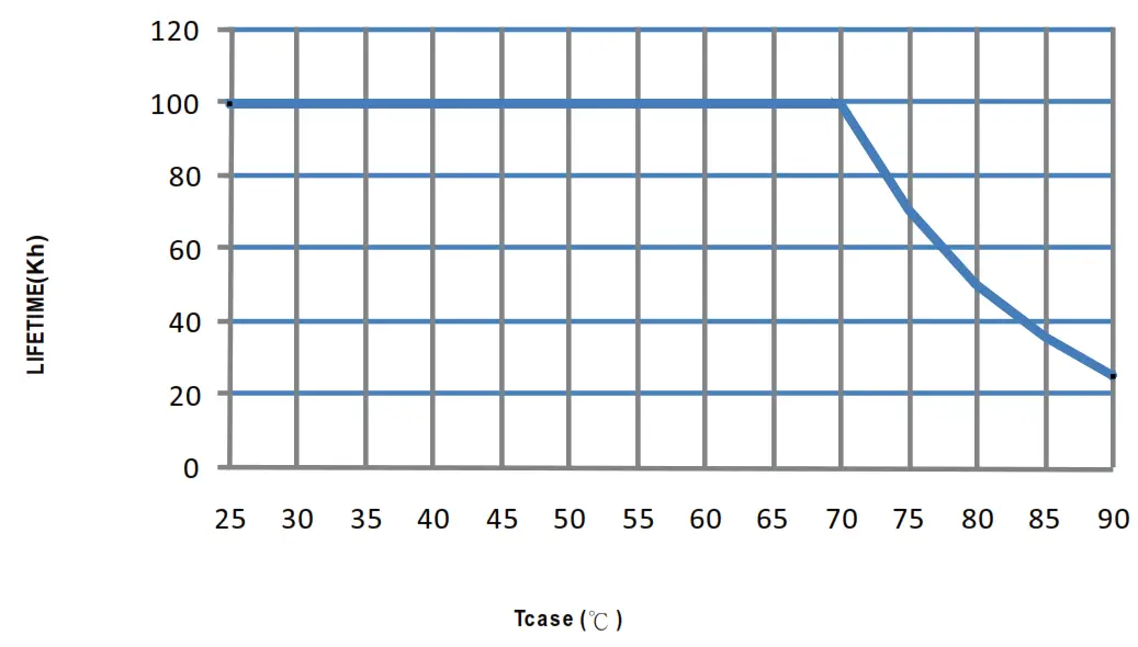
- Life time >50,000 hrs. and 5 years warranty
Applications
- Skyscraper lighting
- Street lighting
- Floodlight Lighting
- Stage lighting
- Fishing lighting
- Horticulture lighting
- Bay lighting
- DMX power supply
- Type HL for use in class I , Division 2
GTIN CODE
MW Search. https://www.meanwell.com/serviceGTIN.aspx
Description
XLG-100 series is a 100W LED AC/DC driver featuring the constant power mode.XLG-100 operates from 100-305VAC and offers models with different rated current ranging between 700mA and 8000mA. Thanks to the high efficiency up to 92%, with the fanless design, the entire series is able to operate for – 40t -+90 C case temperature under free air convection. The design of metal housing and IP67 ingress protection level allows this series to fit both indoor and outdoor applications. Moreover the innovative environment-adaptive capability allows this series to reliably light on the LEDs for all kinds of application environments in almost any spots that may install LED luminaires in the world. XLG-100 series comply with the latest version of IEC61347/GB7000.1-2015 and UL8750 international safety regulations. The output and dimming circuit are also completely in accordance with the new regulations with isolation to ensure the safety of both user and luminaire system during installation.
Model Encoding
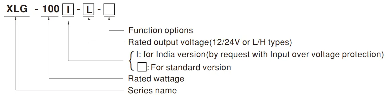
| Type | Function | Note |
| Blank | lo and Vo fixed. (For harsh environment) | By request |
| A | lo adjustable via built-in potentiometer | In Stock |
| AB | lo adjustable via built-in potentiometer +3 in 1 dimming function (0-10Vdc, 10V PWM signal and resistance) | In Stock |
Note:
- 12V and 24V models without the AB type
- India version needs MOO for production, please consult MEANWELL for detail
SPECIFICATION
| MODEL | XLG-100 | XLG-100 | |||
| OUTPUT | DC VOLTAGE | 12V | 24V | ||
| CONSTANT CURRENT REGIONNoin | 8.4- 12V | 16.8-24V | |||
| RATED CURRENT (Default) | 8A | 4A | |||
| RATED P OWER | 96W | 96W | |||
| RIPPLE & NOISE (max.) Nete,3 | 150mVp-p | 240mVp-p | |||
| CURRENT AD./ RANGE | Adjustable fora-bye wily (via the Dui ki n polen &mole() | ||||
| 4 ∼ 8A | 2∼4A | ||||
| VOLTAGE TOLERANCE Ner•A | ±3.0% | ±2.0% | |||
| LINE REGULATION | 31.% | ±0.5% | |||
| LOAD REGULATION | 22% | ±1% | |||
| SETUP, RISE TIME Notch | 500ms. 100msa30VAC. 1200ms. 100(11015VAC | ||||
| HOLDUP TIME flyp.) | 12ms/ 230VAC 12ms/ 115VAC | ||||
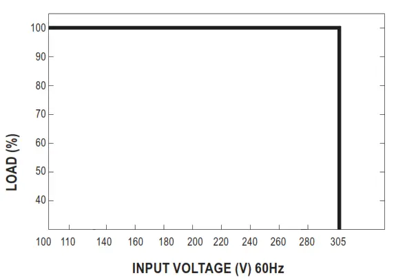
| INPUT | VOLTAGE RANGE NoteS | 100 – 305VAC 142 – 431VDC (Please refer teSTAT IC CHARACTERISTIC’ section) | |||
| FREQUENCY RANGE | 47 – 63Hz | ||||
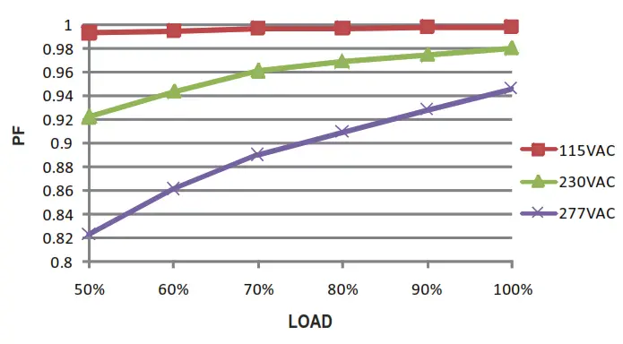
| POWER FACTOR | PF r 027/115VAC. PF .70.95/230VAC. PF -0.92/277VAC(gfull load | ||||
| TOTAL HAMMING DISTORTION | THD<10%(*loadk50%/115VC,230VAC; @loadk75%/277VAC) | ||||
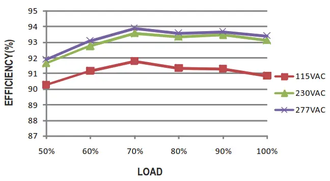
| EFFICIENCY gyp.) | 92% 192% | ||||
| AC CURRENT | 1.1A/ 115VAC 0.5A/230VAC 042A/277VAC | ||||
| INRUSH CU RR ENT(Typ.) | COLD START 50A(tradth=3001s measured at 50% !peak) at 230VAC, Per NEIAA410 | ||||
| MAX. No. of PSUs on I6A CIRCUIT BREAKER | Bonita (circuit breaker of type El) 114 units (circuil breaker of type C) at 230VAC | ||||
| LEAKAGE CURRENT | <0.75mA/ 277VAC | ||||
| NO LOAD POWER CONSUMPTION | No load power consumption <O.5W(for standard version) | ||||
| PROTECTION | OVER CURRENT | 95- 108% | |||
| Hiccup modes Constant a Trent lining, recoversautomatically after bull condition is removed | |||||
| SHORT CIRCUIT | iiccup node or Constant current WON, recovers automatise ty after fault condibon is removed | ||||
| OVERVOLTAGE | 13S -18V | 1 27 – 34V | |||
| SW lean output voltage, re-power o n to recover | |||||
| INPUT OVER VOLTAGE Nor/ | 320 – 390VAC (Shut dawn cued voltege when the input voltage exceals proticlonvoltegtrecerers adomalcale alter tuft condlion is rewired) | ||||
| Can survive input voltage stress of 440Vac for 48 hours @ to 75 C max | |||||
| OVER TEMPERATURE | Shut down output voltage. re lower on to recover | ||||
| ENVIRONMENT | WORKING TEMP. | Tcaser.40 – +90°C (Please refer b’ OUTPUT LOAD vs TEMPERATURE” section) | |||
| MAX. CASE TEMP. | Tcase=+90°C | ||||
| WORKING HUMIDITY | 20 – 95% RH nomcondenang | ||||
| STORAGE TEMP., HUMIDITY | -40- +90°C, 10 – 95% RH | ||||
| TEMP. COEFFICIENT | 30.03%/°C (0 – 60 ‘L.’ I | ||||
| VIBRATION | 10 – 50014,5G 12ritinitcyde, period br 72min. each along X, Y,Z axes | ||||
| EMC SAFETY & | SAFETY STANDARDS Note? | ‘ 111.8750(epelle). UL879. CSA C222 No. 250.13-12: E NEC BS EN/EN61347-1. BS E NE N61347-2-13 independent BS E NE N62381: GB 19510.1, G819510.14:EAC TP TC 004:J61347-1/1129h JS 1 347-2-13(Q9)XC61347-1.KC61347-2-13. 1515885(Part2/Sec13)(fer XIG-1001twe cnly),NOM-058-SCFI.2017(except fa Blank trek I P67 approved | |||
| WITHSTAND VOLTAGE | I/P-0/P:3.75KVAC VP -FG:2KVAC OP -FG:I .5KVAC | ||||
| ISOLATION RESISTANCE | I/P-0/P. I/P-FG . OR -F G:100101011 ms / 500VDC/ 25 C / 70% RH | ||||
| EMC EMISSION | Parameter | Standard | Test Level/Note | ||
| Concluded | 8 S EN/EN55015(CISPRI5) GB/T17743 | —- | |||
| Radiated | BS EN/EN55015(CISPR15) .GB/T17743 | —- | |||
| Harmon ic Cu rrent | 8S EN/EN61000-3 -2 .03/T17625.1 | Class Ca load z50% | |||
| Voltage Filler | BS EN/EMS 10004 -3 | —- | |||
| EMC IMMUNITY | BS E IWEN 61 547 | ||||
| Parameter | Standard | Test LevellNde | |||
| ESD | 8S EN/ EN61000-4 -2 | Level 3. LEV air : Level 2. ‘KV coned | |||
| Radiated | BS EN/EN61000-4 -3 | Level 3 | |||
| EFT/Burst | EIS EN/EN61000-4 -4 | Level 1 | |||
| Surge | BS EN/EN61000-4 -5 | 4KVAile-line 6111Aire-Earet6K/10( Mon) | |||
| Conducted | BS EN/EN61000-4 -6 | Level 3 | |||
| Magnetic Reid | BS EN/EN61000-4 -8 | Level 4 | |||
| Voltage Dps and Interruptions | BS EN/EN61000-4 -11 | >95% dip 0.5 paiorn. 30% by 25 pedals. >95% inleruptims 250 pet& | |||
| OTHERS | MTBF | 2782.6K hrs me. Tekordia SR-332(6.1cm): 276.4Khrs min. ML-H0EIK-217F (25 I: I | |||
| DIMENSION | 140’63 *32rrrn (l.*W*H) | ||||
| PACKING | 0.58Kg:24pcs 115Kg 10,85CUFT | ||||
| NOTE | 1. Al parametersNOT weedily menlionwl we measured al 230VAC Wed rated currenl and 25 cot erten’ lemma:axe. 2. Please rear WI:MK/NGMETHODSOF LED MO DU LE-. 3. Ripple & mese are measured at 20MHzof ban:ISMby useig a 12′ hinged pae-vire terrrinaisdwie a 0.1uf & 47uf parasol capacitor. 4. Tolgerance :includessetup tolgetance,kne regulation and load regulation. 5. De-raling may be needed under lowinpueolages. Please reef to”STATICCHARAC1ERISTIC’seclions lordetait. 6. Lenge ol setup lime Is measured at lirstcold start Turning ONOFF the &Mx may bad b increase ol tie set Lea time. 7. 1rpiAvoltege ore, brX LG-100Iseries, and I soignee-low ULCSA cedficate. 8. The &Maris considered as a ocniponenehatwill be ceeraled in combination witi fiviegdpment Since EMC perlomonoe will be &laded by the complele installation. the final egLipment manulaclurers must requakty EMC Diodes on the °armlet. instalalion again. 9. The amtieneemperalure deraing of 3.5 c /1000m Win lariessmodees and of 5 c/1000m wie Ian medals br operating *rude higher than 2000m(6500f1). 10. Please reed° tie warranl y slatementon MEAN WELL’swetede al http://www.meanwell.com 11. This swiss meets the twecal lie expeclancyol >50.000 hours old:tramwhen Tcase.panicularty 0 pcint (or IMP. per DLC). Is abou1130 Ca less. 12. Prcduds sourced from te Americas regions may not have to PSECCC.iBISIKC Igo. Please contact your MEAN WELL sales br more information. 13. For any appecat tan Me widIP weer woof function 1-sedation caution, please referour user maritalbefore using. https://www.meanwell.com/Upload/PDF/LED_EN.pdf 14. To lulireqUentintol tie latest ErP regulation or lighting lidure. this LED dthercan one be used behind a sr/thy/lout permanenty oonnected b the mains. 15. 1f you need to NOM (Mexico) cerlikcale. Please contact ME AN WELL sales representwire brdetees * Product Liability Discerner : Fa delaied inlormalon. please releto https://www.meanwell.com/serviceDisclaimer.aspx | ||||
SPECIFICATION
| MODEL | XLG-100❑-L- ❑ | XLG-100❑-H- ❑ | |||||
| OUTPUT | RATED CURRENT (Default) | 700mA | 2100mA | ||||
| RATED POWER | 100W | 100W | |||||
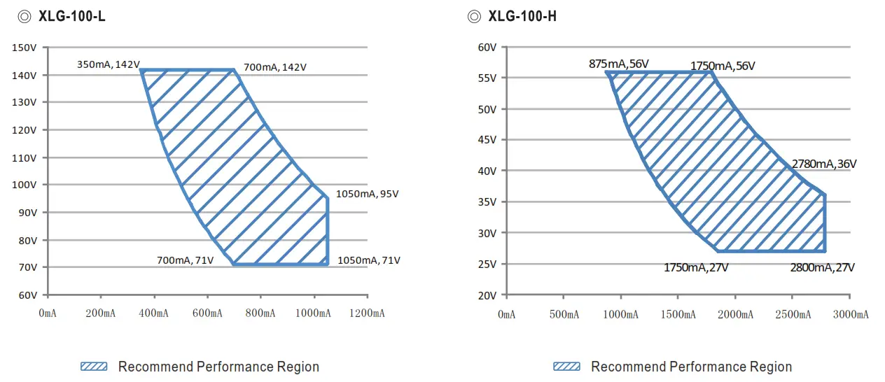
| CONSTANT CURRENT REGION | 71 – 142V | 27∼56V | |||||
| FULL POWER CURRENT RANGE | 700-1050mA | 1750∼2780mA | |||||
| OPEN CIRCUIT VOLTAGE (max.) | 149V | 60V | |||||
| CURRENT ADJ. RANGE | 350-1050mA | 875∼2780mA | |||||
| CURRENT RIPPLE | 3.0%(©ra led current) | ||||||
| CURRENT TOLERANCE | ±5% | ||||||
| SET UP TIME | 500ms/230VAC, 1200ms/115VAC | ||||||
| INPUT | VOLTAGE RANGE Notes | 100∼305VAC 142VDC – 431VDC (Please refer to “STATIC CHARACTERISTIC ang ‘ DRIVING METHODS OF LED MO DU LE”section) | |||||
| FREQUENCY RANGE | 47 – 63Rz | ||||||
| POWER FACTOR T ( yp.) | PF≥0.97 / 115VAC, PF ≥ 0.95 /230VAC, PF≥ 0.92 /277VAC at ful load (Please refer to-Power Factor Characteristic’ section) | ||||||
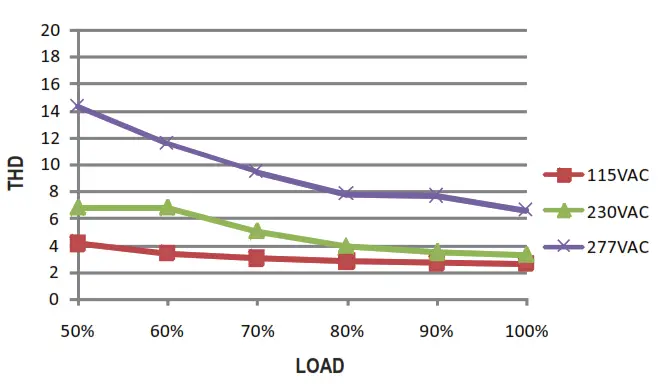
| TOTAL HARMONIC DISTORTION | THD< 10% (@ lode≥50% at 115VAC/230VAC ,@lode≥ 75% at 277VAC) Please refer to”TOTAL HARMONIC DISTORTION (THD)” section | ||||||
| EFFICIENCY (Typ.) | 93.% | 191% | |||||
| AC CURRENT (Typ.) | 1.1A/ 115VAC 0.5A/ 230VAC 0.42A /277VAC | ||||||
| INRUSH CU R RENT(Typ.) | COLD START 50A(hwah=303pis measured at 50% Ipea) at 230VAC: Per NEMA 410 | ||||||
| MAX. NO. of PSUs on 16A CIRCUIT BREAKER | 8 unit(cicuit breaker of type B)/ 14 units(circuit breaker of type C) at 230VAC | ||||||
| LEAKAGE CURRENT | <0.75mA/277VAC | ||||||
| STANDBY POWER CONSUMPTION | Standby power consumption <0.5W for AB-Type(Dimminp OFF)(for standard version) | ||||||
| OVER POWER 105 -150% | |||||||
| Hiccup mode, recovers automatical y after fault condition is removed | |||||||
| SHORT CIRCUIT | Hiccup mode or Constant current imiting, recoversautomaticaly after fault condition is removed | ||||||
| PROTECTION | OVER VOLTAGE | 160 -220V 166 – 90V | |||||
| Shut down output vol tag e, re-power on to recover | |||||||
| INPUT OVER VOLTAGE Note.? | 320- 390VAC (Shut down ouPut voltage when the kWvoltage exceeds aotctbnvoltage, recovers autanaticaly after la tit ccod fa) is removed) | ||||||
| Can survive input voltage stress of 440Vac for 48 hours (Qtc 75°C max | |||||||
| OVER TEMPERATURE | Shut down output voltag e, re-power on to recover | ||||||
| WORKING TEMP. | Tcase=-40 – +90t (Please refer to ‘OUTPUT LOAD vsTEMPERATURE-section) | ||||||
| MAX. CASE TEMP. | Tcase=+90°C | ||||||
| WORKING HUMIDITY | 20 -95% RH non-condensing | ||||||
| ElINROIMENT | STORAGE TEMP., HUMIDITY | -40 ∼ +80°C, 10 – 95% RH non-condensing | |||||
| TEMP. COEFFICIENT | ±0.03%/°C (0 ∼60°C) | ||||||
| VIBRATION | 10 -500Hz, 56 12min.11cyde, period for 72min. each along X, Y, Z axes | ||||||
| SAFETY STANDARDS Note.7 | UL8750(type”HLD, CSA C22.2 No.250.13-12; ENEC BS EN/EN61347-1, BS EN/EN61347-2-13 independent, BS EN/EN62384; GB19510.1 , GB19510.14; EAC TP TC 004;J61347-1(H29), J61347-2-13(H29),KC61347-1,KC61347-2-13, IS15885(Part2Sec13)(for XLG-1001 type only)NOM-058-SCF1-2017(except fa Blank type); IP67 approved | ||||||
| SAFETY & | WITHSTAND VOLTAGE | I/P-0/P:3.75KVAC I/ P-F G:2KVAC 0/P-FG:1.5KVAC | |||||
| ISOLATION RESISTANCE | I/P-O/P, I/P-FG, 0/P-FG: 100M Ohms/ 500VDC / 25C/ 70% RH | ||||||
| EMC | EMC EMISSION | Parameter | Sta ndard | Test Level/Note | |||
| Conducted | BS EN/EN55015(CISPR15) ,GB1T17743 | ||||||
| Radiated | BS EN/EN55015(CISPR15) ,GB/T17743 | ||||||
| Harmonic Current | BS EN/EN61000-3-2 ,GBIT17625.1 | Class C•loada50% | |||||
| Voltage Flicker | BS EN/EN61000-3-3 | ||||||
| E MC IMMUNITY | BS EN/EN61547 | ||||||
| Parameter | Standard | Test Level/Note | |||||
| ES D | BS EN/EN61000-4-2 | Level 3, 810( air ; Level 2, 410/ caitact | |||||
| Radiated | BS EN/ EN61000-4-3 | Level 3 | |||||
| EFT/Burst | BS EN/EN61000.4-4 | Level 3 | |||||
| Surge | BS EN/EN61000.4-5 | 4 KV/Lint> Line 6KV/Lint>Earth(6K/10K optim) | |||||
| Conducted | BS EN/EN61000.4-6 | Level 3 | |||||
| Magnetic Field | BS EN/EN61000-4-8 | Level 4 | |||||
| Voltage Dips and Interruptions | BS EN/EN61000.4-11 | >95% dp 05 periods. 30% dp 25 periods, >95% inbarruptions 250 periods | |||||
| MT BF | 2782.6K hrs min. Teloordia SR-332 (Bellcore); 276.4Khrs min. MIL-HDBK-217F (25C ) | ||||||
| OTHERS | DIMENSION | 140’6312mm (L’W*1-1) | |||||
| PACKING | 0.58Kg;24pcs /15Kg /0.85CUFT | ||||||
| NOTE | 1. All parameters NOT specialty mentioned are mangrred at 230VAC input rated current and 25 c of ambient temperature. 2. Please refer to ‘DRIVING METHODS OF LED MODULE’. 3. Ripple& noise are measured at 20MHz of bandwidth by using a 12- twisted pair-wire terminated with a 0.1 uf & 47uf parallel capacitor. 4. Tolerance : includes set up tolerance, line regulation and bad regulation. 5. De-rating may be needed under low input voltages. Please refer to *STATIC CHARACTERISTIC sections for details. 6. Length of set up time is measured at first cold start. Turning ON/OFF the driver may lead to increase of the set up time. 7. Input voltage only for XLG-100 I series, and I series without UL/CSA certificate. 8. The driver is considered as a component that will be operated in combination with final equipment. Since EMC performancewill be affected by the complete installation, the final equipment manufacturers must re-qualify E MC Directive on the complete installation again. 9. The ambient temperature derating of 35 c/1000m with fanless models and of 5 c/1000m with fan models for operating altitude higher than 2000m(650010. 10. Please refer to the warranty statement on MEAN WE Lt.’s webs ile at http://www.meanwell.com 11. This series meets the typical life expectancy of >50,000 hours of operation when Tcase, panicularty 0 point (or TMP, per DLC), is about 80 C or less. 12. Products sourced from the Americas regions may not have the P SE/Gee/BS/KC logo. Please contact your MEAN WELL sales for more information. 13. For any application note and IPwater proof function installation caution, please refer our user manual before using. https://www.meanwell.com/Upload/PDF/LED_EN.pdf14. To fulfill requirements of the latest ErP regulation for lighting fixture, this LED driver can only be used behind a switch without permanently connected to the mains. 15. If you need the NOM (Mexico) certificate, Please contact MEAN WELL sales representative for details. * Product Liability Disclaimer : For detailed informaton, please refer to https://www.meanwell.com/serviceDisclaimer.aspx | ||||||
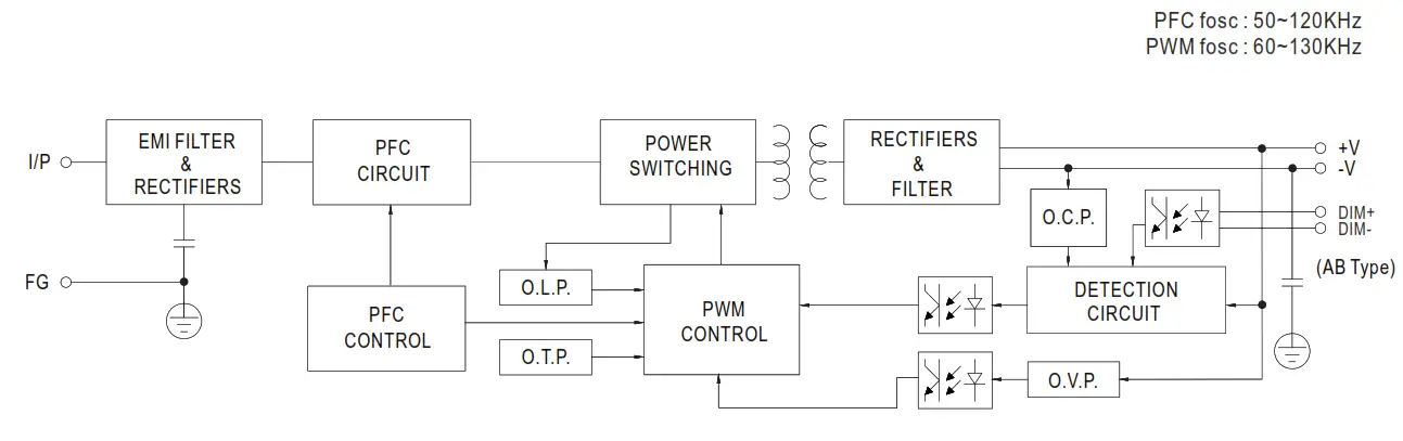
BLOCK DIAGRAM
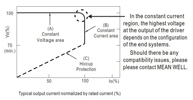
DRIVING METHODS OF LED MODULE
※ -I V Operating Area
LXG-100-12,24
※ This series is able to work in either Constant Current mode (a direct drive way) or Constant Voltage mode (usually through additional DC/DC driver) to drive the LEDs.
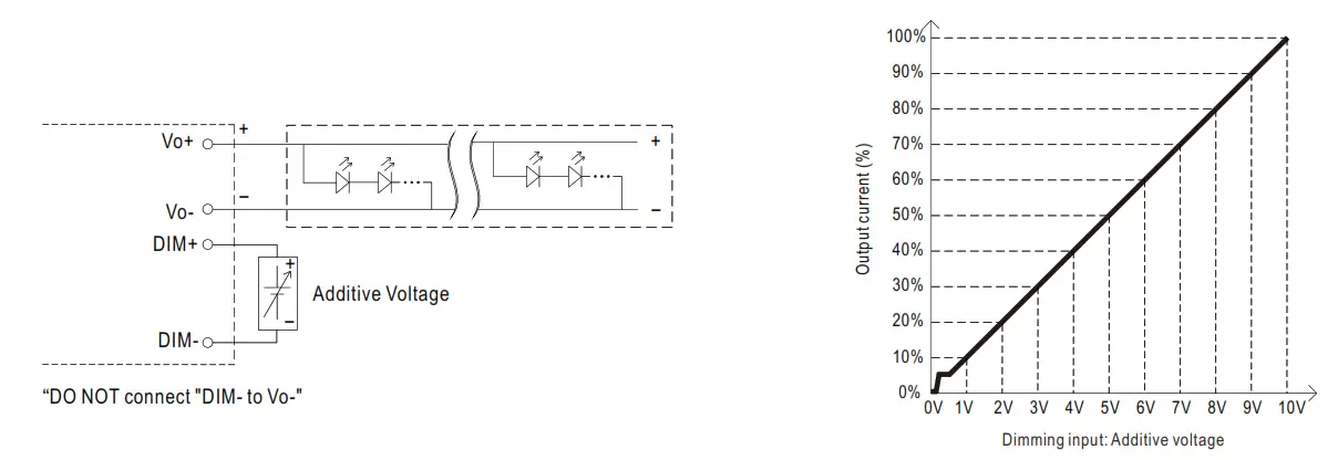
DIMMING OPERATION
※ 3 in 1 dimming function (for AB-Type)
- Output constant current level can be adjusted by applying one of the three methodologies between DIM+ and DIM-: 0 ~ 10VDC, or 10V PWM signal or resistance.
- Direct connecting to LEDs is suggested. It is not suitable to be used with additional drivers.
- Dimming source current from power supply: 100 μA (typ.)
APPlying additive 0∼10VDC
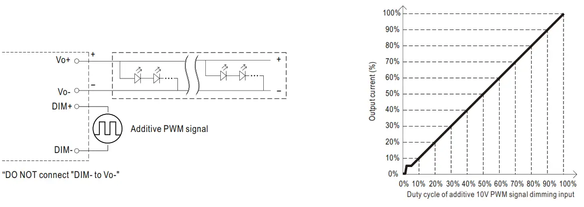
©Applying additive 10V PWM signal (frequency range 100Hz ∼3KHz):
 © Applying additive resistance:
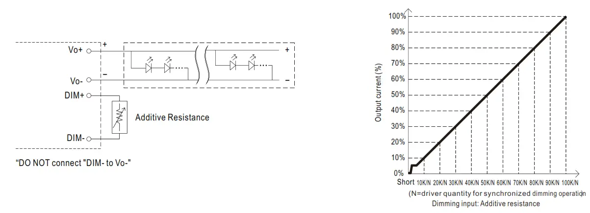
Note :
- Min. dimming level is about 8% and the output current is not defined when 0%< Iout<8%.
- The output current could drop down to 0% when dimming input is about 0kΩ or 0Vdc, or 10V PWM signal with 0% duty cycle.
OUTPUT LOAD vs TEMPERATURE
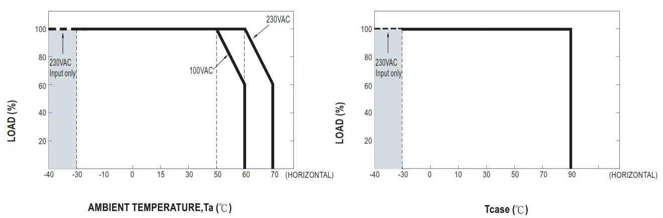
If XLG-100 operates in Constant Current mode with the rated current the maximum workable Ta is 60 ℃(Typ. 230VAC) or 50℃ (Typ.100VAC)
Below 110VAC@ -30℃ may retry to 2nd setup
STATIC CHARACTERISTIC
TOTAL HARMONIC DISTORTION (THD)
※XLG-100-L Model, Tcase at 75 C
POWER FACTOR (PF) CHARACTERISTIC
※Tcase at 75°C
Constant Current Mode
EFFICIENCY vs LOAD
XLG-100 series possess superior working efficiency that up to 92.5% can be reached in field applications.
※ XLG-100-L Model, Tcase at 75 ℃
LIFE TIME
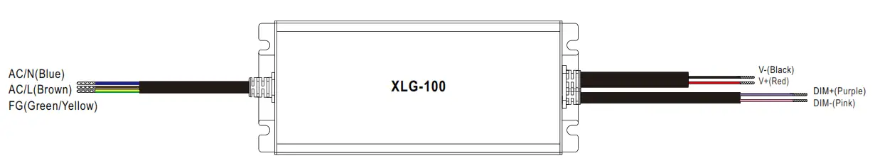
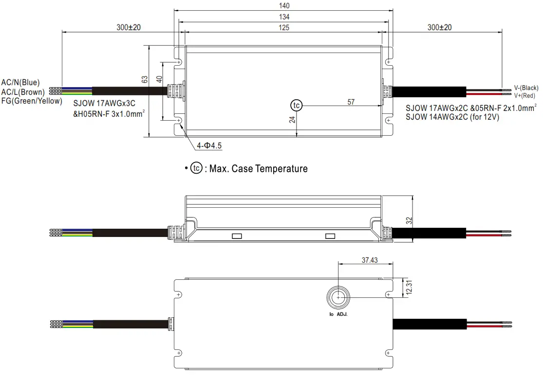
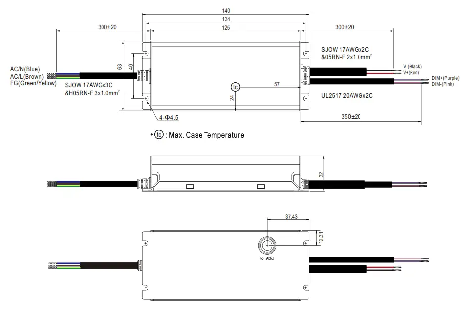
MECHANICAL SPECIFICATION
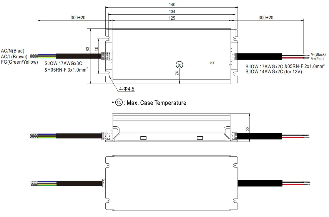
※ A-Type
※ AB-Type
INSTALLATION MANUAL
Please refer to : http://www.meanwell.com/manual.html


