 650W Constant Power Mode LED Driver
HVGC-650 series
User’s Manual
![]()
![]()
■ Features
- Wide input range 180 ~ 528VAC
- Constant power mode output
- Metal housing with Class I design
- Surge protection with 8KV/4KV
- Built-in active PFC function
- IP67 design for indoor or outdoor installations
- Function options. output adjustable via potentiometer; 3 in 1 dimming (dim-to-off); Smart timer dimming
- Auxiliary DC output optional
- Typical lifetime>50000 hours
- 5 years warranty
■ Applications
- Harbor lighting
- LED high-bay lighting
- Parking lot lighting
- LED fishing lamp
- Horticulture lighting
- Stadium lighting
- Type “HL” for use in Class I , Division 2 hazardous (Classified) location.
■ GTIN CODE
MW Search: https://www.meanwell.com/serviceGTIN.aspx
■ Description
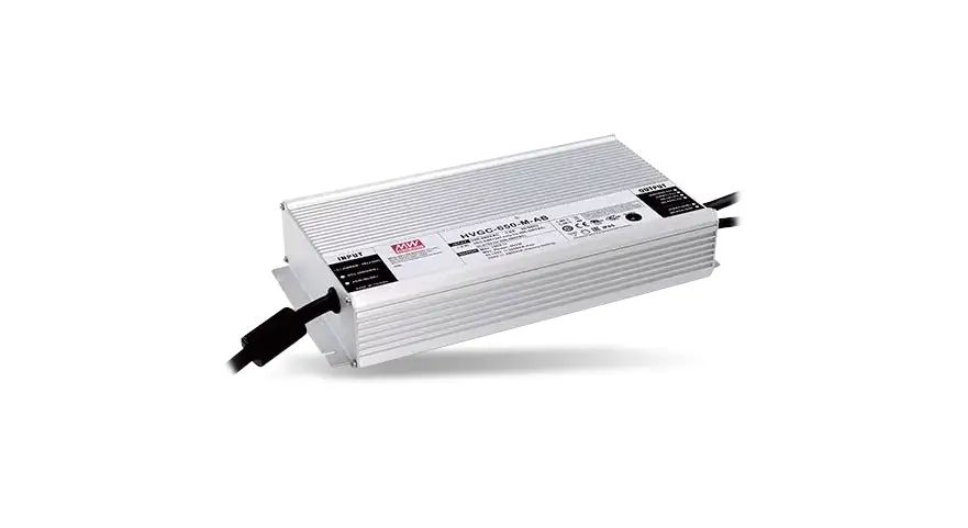
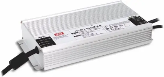
HVGC-650 series is a 650W LED AC/DC driver featuring the constant power mode with wide output voltage range. HVGC-650 operates from 180~528VAC and offers models with different rated current ranging between 2800mA and 14000mA. Thanks to the high efficiency up to 95.5%, with the fanless design, all models are able to operate for -40°C~+85°C case temperature under free air convection. The design of metal housing and IP67 ingress protection level allows this series to fit both indoor and outdoor applications, such as horticulture lighting and stadium light HVGC-650 is equipped with various function options, such as dimming methodologies, so as to provide the optimal design flexibility for LED lighting system.
■ Model Encoding
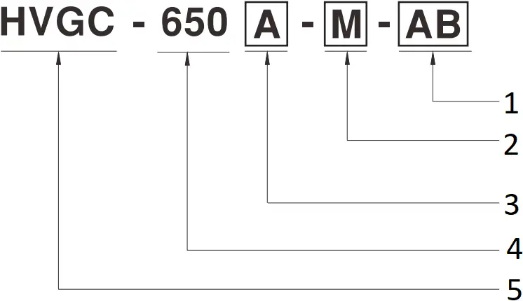
- Function options
- Rated output current(2800/4200/5600/11200mA)
- {A : Auxiliary DC output(12V@200mA)(by request)
 : None
 - Rated wattage
- Series name
Type | IP Level | Function | Note |
AB | IP67 | Standard constant power output with 3 in 1 dimming function (0~10Vdc, 10V PWM signal and resistance) and built-in potentiometer. | In Stock |
D2 | IP67 | Built-in Smart timer dimming and programmable function. | By request |
Dx | IP67 | Built-in Smart timer dimming function by user request. | By request |
DA | IP67 | DALI control technology with lo Adjustable via built-in potentiometer. | By request |
SPECIFICATION
| MODEL | HVGC-650 | HVGC-650 | HVGC-650 | HVGC-650 | |
| OUTPUT | RATED CURRENT | 2800mA | 4200mA | 5600mA | 11200mA |
| RATED POWER | 649.6W | 651W | 649.6W | 649.6W | |
| CONSTANT CURRENT REGION Note.2 | 92.8 ~ 232V | 62 ~ 155V | 46.4 ~ 116V | 24 ~ 58V | |
| FULL POWER CURRENT RANGE | 2800~3500mA | 4200~5250mA | 5600~7000mA | 11200~14000mA | |
| OPEN CIRCUIT VOLTAGE (max.) | 240V | 160V | 120V | 70V | |
| CURRENT ADJ. RANGE | 1400~3500mA | 2100~5250mA | 2800~7000mA | 5600~14000mA | |
| CURRENT RIPPLE | 5.0% max. @rated current | ||||
| CURRENT TOLERANCE | ±5% | ||||
| AUXILIARY POWER | Nominal 12V (Tolerance: ±10%, R&N:150mVp-p)@200mA for HVGC-650A only | ||||
| SET UP TIME Note.4 | 500ms/230VAC, 347VAC, 480VAC | ||||
| INPUT | VOLTAGE RANGE Note.3 | 180 ~ 528VAC 254VDC ~ 747VDC (Please refer to “STATIC CHARACTERISTIC” section) | |||
| FREQUENCY RANGE | 47 ~ 63Hz | ||||
| POWER FACTOR (Typ.) | PF≧0.98 / 230VAC, PF≧0.98 / 277VAC, PF≧0.97 / 347VAC, PF≧0.96 / 400VAC, PF≧0.95 / 480VAC at full load (Please refer to “Power Factor Characteristic” section) | ||||
| TOTAL HARMONIC DISTORTION | THD< 20% (@ load≧50% at 230VAC/277VAC/347VAC/400VAC/480VAC input (Please refer to “TOTAL HARMONIC DISTORTION (THD)” section) | ||||
| EFFICIENCY (Typ.) | 95% | 95% | 95% | 95.5% | |
| AC CURRENT (Typ.) | 2.1A / 347VAC 1.5A / 480VAC | ||||
| INRUSH CURRENT(Typ.) | COLD START 40A(twidth=1250 s measured at 50% Ipeak) at 480VAC; Per NEMA 410 | ||||
| MAX. NO. of PSUs on 16A CIRCUIT BREAKER | 2 unit(circuit breaker of type B) / 4 units(circuit breaker of type C) at 480VAC | ||||
| LEAKAGE CURRENT | <0.75mA / 480VAC | ||||
| PROTECTION | SHORT CIRCUIT | Constant current limiting, recovers automatically after fault condition is removed | |||
| OVER VOLTAGE | 240 ~ 259V | 158 ~ 178V | 118 ~ 136V | 62 ~ 78V | |
| Shut down output voltage, re-power on to recovery | |||||
| OVER TEMPERATURE | Shut down output voltage, re-power on to recovery | ||||
| ENVIRONMENT | WORKING TEMP. | Tcase=-40 ~ +85℃(Please refer to “OUTPUT LOAD vs TEMPERATURE” section) | |||
| MAX. CASE TEMP. | Tcase=+85℃ | ||||
| WORKING HUMIDITY | 20 ~ 95% RH non-condensing | ||||
| STORAGE TEMP., HUMIDITY | -40 ~ +80℃, 10 ~ 95% RH non-condensing | ||||
| TEMP. COEFFICIENT | ±0.03%/℃ (0 ~ 55℃) | ||||
| VIBRATION | 10 ~ 500Hz, 5G 12min./1cycle, period for 72min. each along X, Y, Z axes | ||||
| SAFETY & EMC | SAFETY STANDARDS | UL8750 (type”HL”), CSA C22.2 No. 250.13-12, ENEC BS EN/EN613471-2-16, BS EN/EN60384, IP67, EAC TP TC 004 approved | |||
| WITHSTAND VOLTAGE | I/P-O/P:4.2KVAC I/P-FG:2.1KVAC O/P-FG:1.5KVAC | ||||
| ISOLATION RESISTANCE | I/P-O/P, I/P-FG, O/P-FG:100M Ohms / 500VDC / 25℃/ 70% RH | ||||
| EMC EMISSION | Compliance to BS EN/EN55015, BS EN/EN61000-3-2 Class C (@ load≧50%); BS EN/EN61000-3-3, FCC Part 15 class B, EAC TP TC 020 | ||||
| EMC IMMUNITY | Compliance to BS EN/EN61000-4-2,3,4,5,6,8,11, BS EN/EN61547, light industry level (surge immunity Line-Earth 8KV, Line-Line 4KV), EAC TP TC 020 | ||||
| OTHERS | MTBF | 728.1K hrs min. Telcordia SR-332(Bellcore) ; 60.2K hrs min. MIL-HDBK-217F (25℃) | |||
| DIMENSION | 280*144*48.5mm (L*W*H) | ||||
| PACKING | 3.9Kg;4pcs/16.6Kg/0.98CUFT | ||||
| NOTE |
※ Product Liability Disclaimer : For detailed information, please refer to https://www.meanwell.com/serviceDisclaimer.aspx | ||||
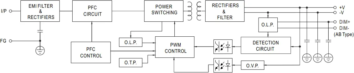
■ BLOCK DIAGRAM
■ DRIVING METHODS OF LED MODULE
※ I-V Operating Area
![]() HVGC-650-L
HVGC-650-L
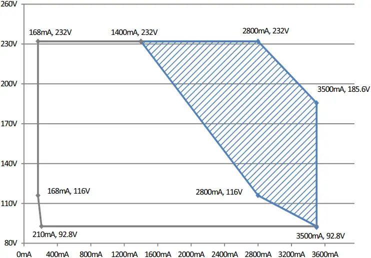
![]() Recommended High Performance Region
Recommended High Performance Region ![]() Allowed Operational Region
Allowed Operational Region
![]() HVGC-650-M
HVGC-650-M
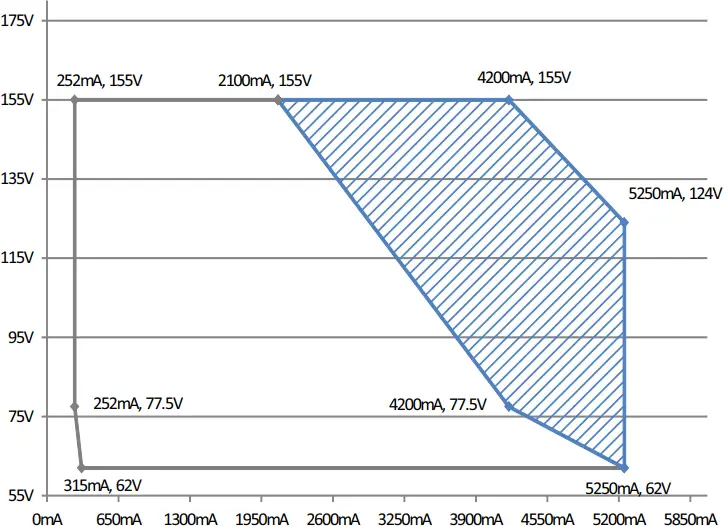
![]() Recommended High Performance Region
Recommended High Performance Region ![]() Allowed Operational Region
Allowed Operational Region
![]() HVGC-650-H
HVGC-650-H
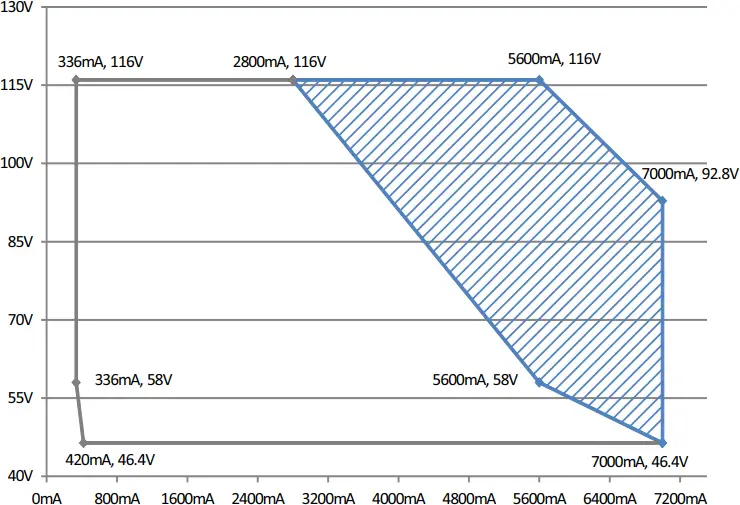
![]() Recommended High Performance Region
Recommended High Performance Region ![]() Allowed Operational Region
Allowed Operational Region
![]() HVGC-650-U
HVGC-650-U
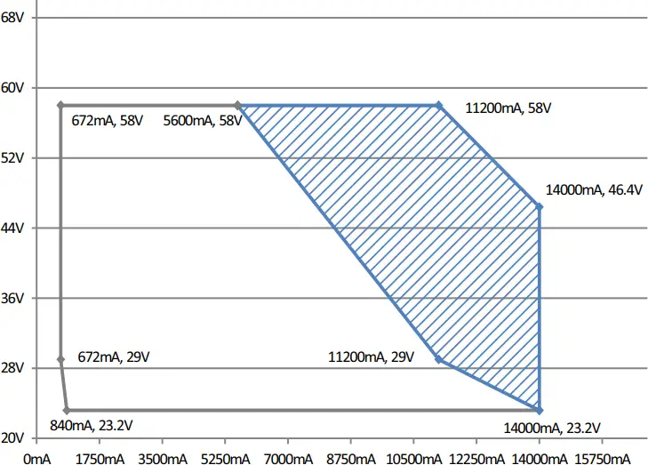
![]() Recommended High Performance Region
Recommended High Performance Region ![]() Allowed Operational Region
Allowed Operational Region
■ DIMMING OPERATION
- FG
 (Green/Yellow)
AC/L(Brown)
AC/N(Blue) - Vo+(Red)
Vo+(Red)
Vo-(Black)
Vo-(Black) - DIM+(Blue)*
DIM-(White)**
* DIM+ for AB-Type
PROG+ for D2-Type
DA+ for DA-Type
* *DIM- for AB-Type
PROG- for D2-Type
DA- for DA-Type
※ 3 in 1 dimming function (for Blank-Type)
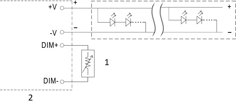
- Output constant current level can be adjusted by applying one of the three methodologies between DIM+ and DIM-:
0 ~ 10VDC, or 10V PWM signal or resistance. - Direct connecting to LEDs is suggested. It is not suitable with additional drivers. to be used
- Dimming source current from power supply: 100μA (typ.)
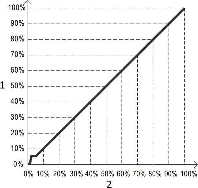
![]() Applying additive 0 ~ 10VDC
Applying additive 0 ~ 10VDC
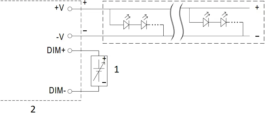
- Additive Voltage
- “DO NOT connect “DIM- to -V”
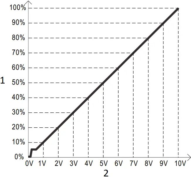
- Output current (%)
- Dimming input: Additive voltage
![]() Applying additive 10V PWM signal (frequency range 100Hz ~ 3KHz):
Applying additive 10V PWM signal (frequency range 100Hz ~ 3KHz):
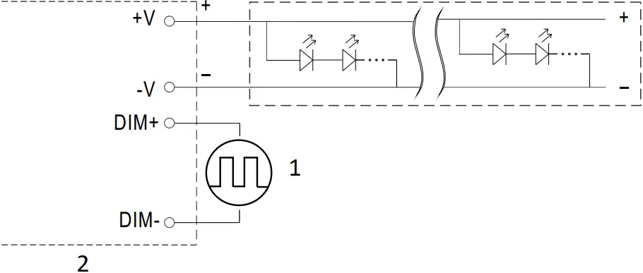
- Additive PWM signal
- “DO NOT connect “DIM- to -V”
- Output current (%)
- Duty cycle of additive 10V PWM signal dimming input
![]() Applying additive resistance:
Applying additive resistance:
- Additive PWM signal
- “DO NOT connect “DIM- to -V”
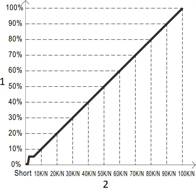
- Output current (%)
- (N=driver quantity for synchronized dimming operation)
Dimming input: Additive resistance
Note :
- Min. dimming level is about 6% and the output current is not defined when 0%< Iout<6%.
- The output current could drop down to 0% when dimming input is about 0kΩ or 0Vdc, or 10V PWM signal with 0% duty cycle.
※ Smart timer dimming function (for Dxx-Type by User definition)
MEAN WELL Smart timer dimming primarily provides the adaptive proportion dimming profile for the output constant current level to perform up to 14 consecutive hours. 3 dimming profiles hereunder are defined accounting for the most frequently seen applications. If other options may be needed, please contact MEAN WELL for details.
Ex : ![]() D01-Type: the profile recommended for residential lighting
D01-Type: the profile recommended for residential lighting
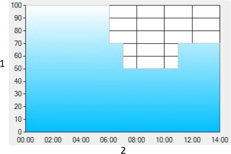
- Dimming Level(%)
- Operating Time(HH:MM)
Set up for D01-Type in Smart timer dimming software program:
T1 | T2 | T3 | T4 | |
TIME** | 06:00 | 07:00 | 11:00 | — |
LEVEL** | 100% | 70% | 50% | 70% |
**: TIME matches Operating Time in the diagram whereas LEVEL matches Dimming Level.
Example: If a residential lighting application adopts D01-Type, when turning on the power supply at 6:00pm, for instance:
[1] The power supply will switch to the constant current level at 100% starting from 6:00pm.
[2] The power supply will switch to the constant current level at 70% in turn, starting from 0:00am, which is 06:00 after the power supply turns on.
[3] The power supply will switch to the constant current level at 50% in turn, starting from 1:00am, which is 07:00 after the power supply turns on.
[4] The power supply will switch to the constant current level at 70% in turn, starting from 5:00am, which is 11:00 after the power supply turns on.
The constant current level remains till 8:00am, which is 14:00 after the power supply turns on.
Ex: ![]() D02-Type: the profile recommended for street lighting
D02-Type: the profile recommended for street lighting
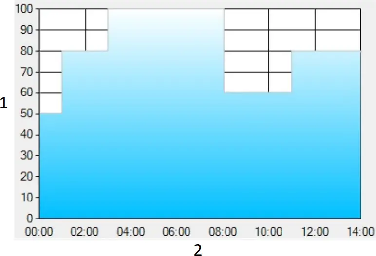
- Dimming Level(%)
- Operating Time(HH:MM)
Set up for D02-Type in Smart timer dimming software program:
T1 | T2 | T3 | T4 | T5 | |
| TIME** | 01:00 | 03:00 | 08:00 | 11:00 | — |
| LEVEL** | 50% | 80% | 100% | 60% | 80% |
**: TIME matches Operating Time in the diagram whereas LEVEL matches Dimming Level.
Example: If a street lighting application adopts D02-Type, when turning on the power supply at 5:00pm, for instance:
[1] The power supply will switch to the constant current level at 50% starting from 5:00pm.
[2] The power supply will switch to the constant current level at 80% in turn, starting from 6:00pm, which is 01:00 after the power supply turns on.
[3] The power supply will switch to the constant current level at 100% in turn, starting from 8:00pm, which is 03:00 after the power supply turns on.
[4] The power supply will switch to the constant current level at 60% in turn, starting from 1:00am, which is 08:00 after the power supply turns on.
[5] The power supply will switch to the constant current level at 80% in turn, starting from 4:00am, which is 11:00 after the power supply turns on. The constant current level remains till 6:30am, which is 14:00 after the power supply turns on.
Ex: ![]() D03-Type: the profile recommended for tunnel lighting
D03-Type: the profile recommended for tunnel lighting
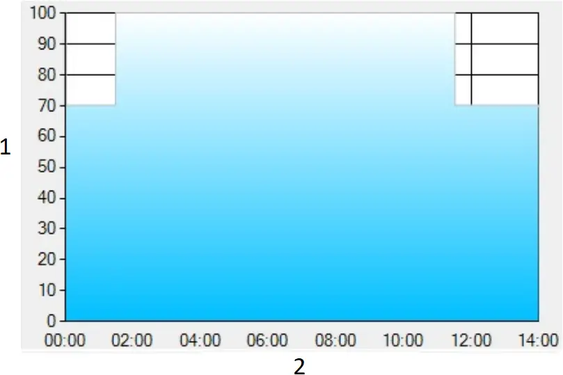
- Dimming Level(%)
- Operating Time(HH:MM)
Set up for D03-Type in Smart timer dimming software program:
T1 | T2 | T3 | T4 | |
| TIME** | 18:00 | 20:00 | 24:00 | 04:00 |
| LEVEL** | 100% | 75% | 50% | 25% |
**: TIME matches Operating Time in the diagram whereas LEVEL matches Dimming Level.
Example: If a tunnel lighting application adopts D03-Type, when turning on the power supply at 4:30pm, for instance:
[1] The power supply will switch to the constant current level at 70% starting from 4:30pm.
[2] The power supply will switch to the constant current level at 100% in turn, starting from 6:00pm, which is 01:30 after the power supply turns on.
[3] The power supply will switch to the constant current level at 70% in turn, starting from 5:00am, which is 11:00 after the power supply turns on.
The constant current level remains till 6:30am, which is 14:00 after the power supply turns on.
※ DALI interface(primary side; for DA-Type)
- Apply DALI signal between DA+ and DA-.
- DALI protocol comprises 16 groups and 64 addresses.
- First step is fixed at 6% of output.
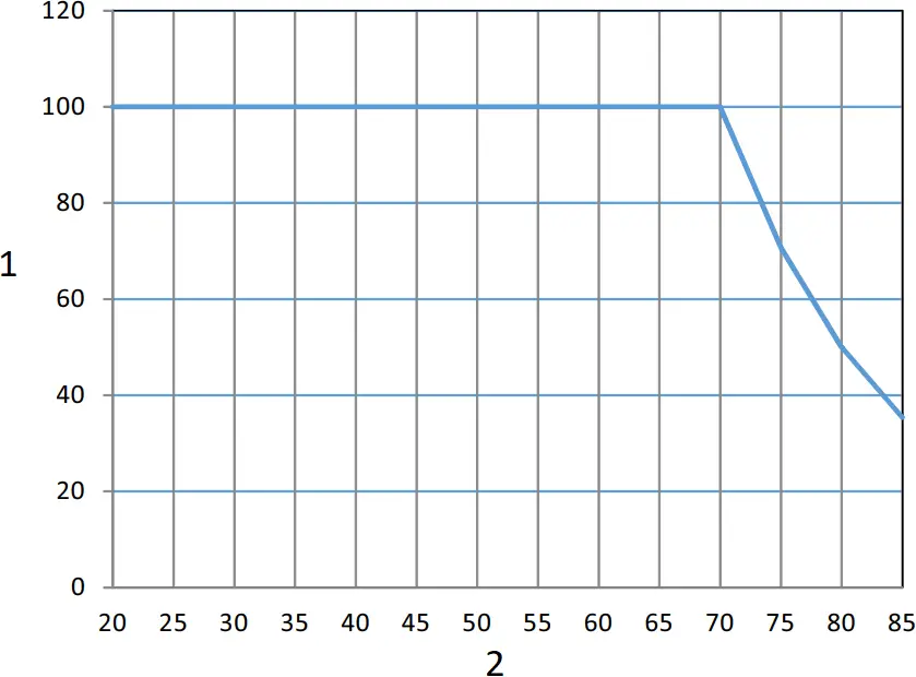
■ OUTPUT LOAD vs TEMPERATURE
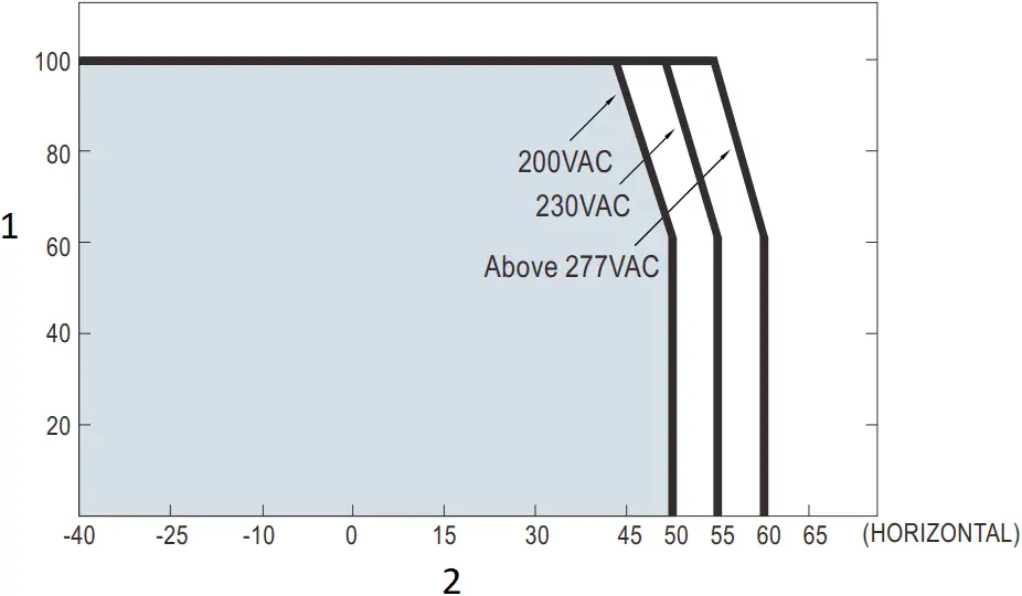
- LOAD (%)
- AMBIENT TEMPERATURE,Ta (°C)
If HVGC-650 operates in Constant Power mode with the rated current, the maximum workable Ta is 50℃(Typ. 230VAC)
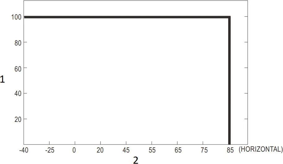
- LOAD (%)
- Tcase (°C)
■ STATIC CHARACTERISTIC
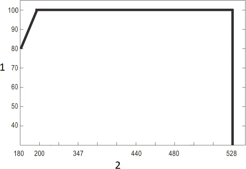
- LOAD (%)
- INPUT VOLTAGE (V) 60Hz
■ POWER FACTOR (PF) CHARACTERISTIC
※ Tcase at 80℃
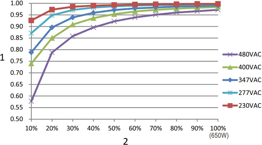
- PF
- LOAD
■ TOTAL HARMONIC DISTORTION (THD)
※ L Model, Tcase at 80℃

- THD(%)
- LOAD
■ EFFICIENCY vs LOAD
HVGC-650 series possess superior working efficiency that up to 95% can be reached in field applications.
※ L Model, Tcase at 80℃
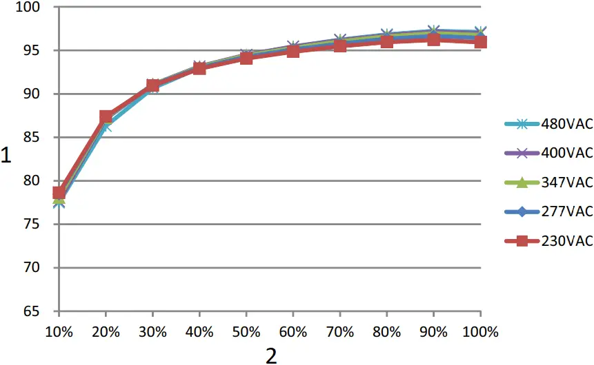
- EFFICIENCY(%)
- LOAD
■ LIFE TIME
- LIFETIME(Kh)
- Tcase (°C)
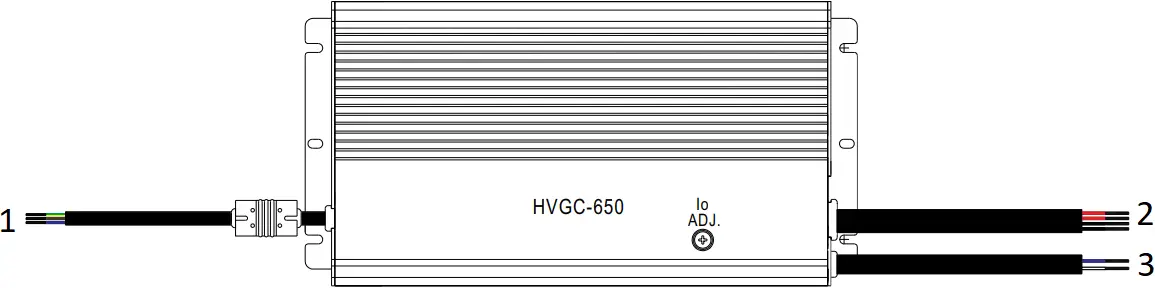
■ MECHANICAL SPECIFICATION
Cable information
Type | Input cable | Output cable | Dimming cable | AUX cable |
AB | SOOW 17AWG 3C / H07RN-F 3G 1.0mm² | U type: SJOW 17AWG 4C / H05RN-F L/M/H type: SJOW 17AWG 2C / H05RN-F | SJOW 17AWG 2C / H05RN-F | SJOW 17AWG 2C / H05RN-F |
D2 | SOOW 17AWG 3C / H07RN-F 3G 1.0mm² | U type: SJOW 17AWG 4C / H05RN-F L/M/H type: SJOW 17AWG 2C / H05RN-F | SJOW 17AWG 2C / H05RN-F | SJOW 17AWG 2C / H05RN-F |
Dx | SOOW 17AWG 3C / H07RN-F 3G 1.0mm² | U type: SJOW 17AWG 4C / H05RN-F L/M/H type: SJOW 17AWG 2C / H05RN-F | —— | SJOW 17AWG 2C / H05RN-F |
DA | SOOW 17AWG 3C / H07RN-F 3G 1.0mm² | U type: SJOW 17AWG 4C / H05RN-F L/M/H type: SJOW 17AWG 2C / H05RN-F | SJOW 17AWG 2C / H05RN-F | SJOW 17AWG 2C / H05RN-F |
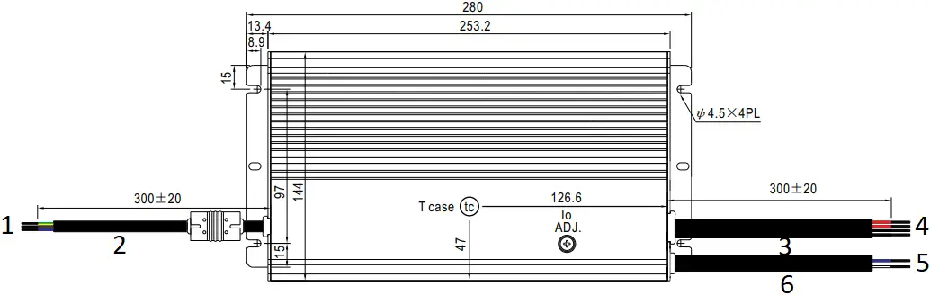
Case No. 228 Unit:mm
※HVGC-650-![]() –
–![]()
![]() = U type
= U type![]() = AB/D2/DA types
= AB/D2/DA types

 : Max. Case Temperature
- FG (Green/Yellow)
AC/L(Brown)
AC/N(Blue) - SOOW 17AWG 3C / H07RN-F 3G 1.0mm²
- SJOW 17AWG 4C / H05RN-F 1.0mm²
- Vo+(Red)
Vo+(Red)
Vo-(Black)
Vo-(Black) - DIM+/PROG+/DA+(Blue)
DIM-/PROG-/DA-(White) - SJOW 17AWG 2C / H05RN-F 1.0mm²
※HVGC-650-![]() –
–![]()
![]() = L/M/H type
= L/M/H type![]() = AB/D2/DA types
= AB/D2/DA types
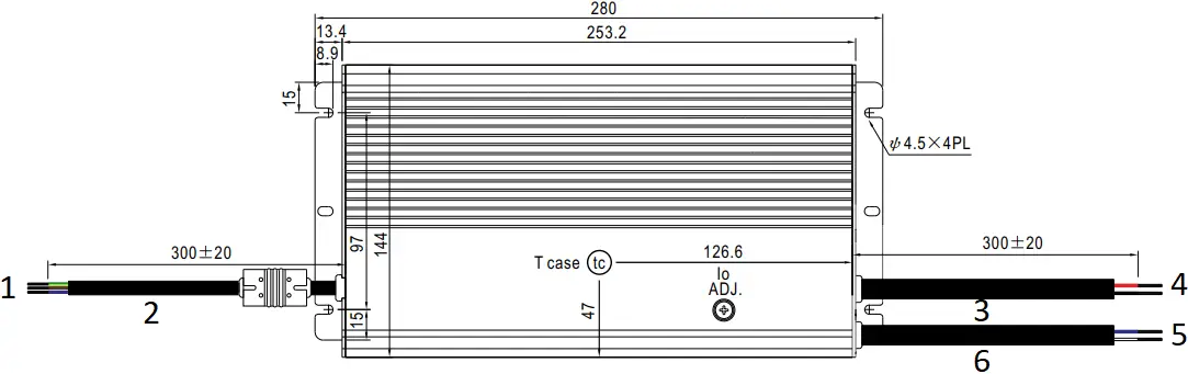

- : Max. Case Temperature
- FG (Green/Yellow)
AC/L(Brown)
AC/N(Blue) - SOOW 17AWG 3C / H07RN-F 3G 1.0mm²
- SJOW 17AWG 2C / H05RN-F 1.0mm²
- Vo+(Red)
Vo-(Black) - DIM+/PROG+/DA+(Blue)
DIM-/PROG-/DA-(White) - SJOW 17AWG 2C / H05RN-F 1.0mm²
Unit:mm
※HVGC-650-![]() –
–![]() with auxiliary power optional
with auxiliary power optional![]() = U type
= U type![]() = AB/D2/DA types
= AB/D2/DA types
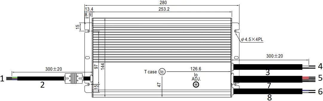

- : Max. Case Temperature
- FG (Green/Yellow)
AC/L(Brown)
AC/N(Blue) - SOOW 17AWG 3C / H07RN-F 3G 1.0mm²
- SJOW 17AWG 2C / H05RN-F 1.0mm²
- AUX+(Gray)
AUX-(Black) - Vo+(Red)
Vo+(Red)
Vo-(Black)
Vo-(Black) - DIM+/PROG+/DA+(Blue)
DIM-/PROG-/DA-(White) - SJOW 17AWG 4C / H05RN-F 1.0mm²
- SJOW 17AWG 2C / H05RN-F 1.0mm²
※HVGC-650-![]() –
–![]() with auxiliary power optional
with auxiliary power optional![]() = L/M/H type
= L/M/H type![]() = AB/D2/DA types
= AB/D2/DA types
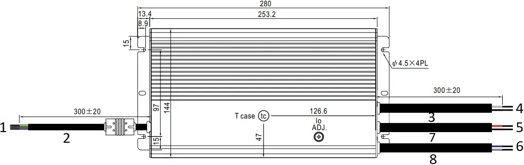

- : Max. Case Temperature
- FG (Green/Yellow)
AC/L(Brown)
AC/N(Blue) - SOOW 17AWG 3C / H07RN-F 3G 1.0mm²
- SJOW 17AWG 2C / H05RN-F 1.0mm²
- AUX+(Gray)
AUX-(Black) - Vo+(Red)
Vo-(Black) - DIM+/PROG+/DA+(Blue)
DIM-/PROG-/DA-(White) - SJOW 17AWG 2C / H05RN-F 1.0mm²
- SJOW 17AWG 2C / H05RN-F 1.0mm²
■ INSTALLATION MANUAL
Please refer to : http://www.meanwell.com/manual.html
File Name:HVGC-650-SPEC 2022-02-21


