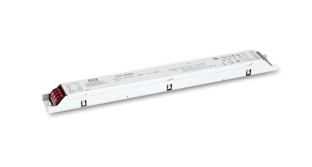
![]() LDC-55 55W Constant Power MODE Linear LED Driver
LDC-55 55W Constant Power MODE Linear LED Driver
User Manual 
![]()
 http://www.meanwell.com.cn/Upload/PDF/LED_EN.pdf
Features
- Constant Power mode output
- Metal housing design
- Full Power at 70~100% max Current
- Built-in active PFC function
- Flicker Free design
- Class 2 power supply
- No load / Standby power consumption <0.5W
- Output current level pre-settable
- Function options: 3 in 1 dimming (dim-to-off); DALI interface, push dimming
- Typical lifetime>50000 hours
- SELV and Isolated
- 5 years warranty
Applications
- LED panel lighting
- Indoor LED lighting
- Linear LED lighting
GTIN CODE
MW Search: https://vww.meanwell.com/serviceGTIN.aspx
Description
LDC-55 series is a55W AC/DC LED driver featuring the Constant Power mode output. LDC-55 operates from 180~295VAC and the output current can be adjusted between 500mA to 1600mA.
Thanks to the efficiency of up to 90%, with the fanless design, the entire series is able to operate for -25C~+80C case temperature under free air convection.LDC-55 is equipped with various function options, such as dimming methodologies, so as to provide the optimal design flexibility for LED lighting systems.
Mi Model Encoding
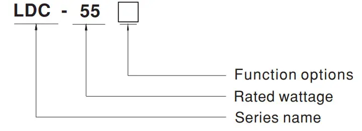
| Type | Function | Note |
| Blank | Non-dimming | In Stock |
| B | 3 in 1 dimming function (0-10Vdc and PWM signal and resistance) | In Stock |
| DA | DALI, push dimming | In Stock |
| DA2 | DALI-2, push dimming | In Stock |
SPECIFICATION
| SPECIFICATION
| ||
| MODEL | LDC-550 | |
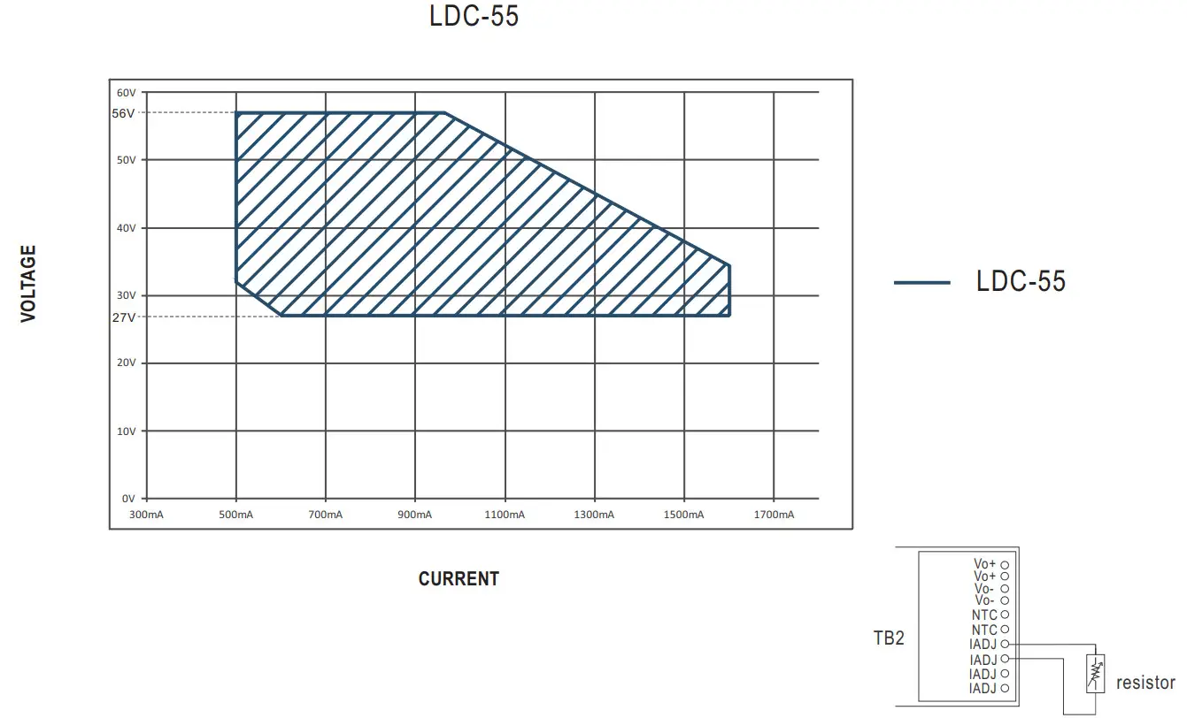
| OUTPUT | OUTPUT CURRENT REGION | 500 – 1600mA(1050mA default) |
| RATED POWER Note.2 | 55W | |
| CONSTANT CURRENT REGION Nod | 27 – 56V | |
| FULL POWER CURRENT RANGE | 980 – 1600mA | |
| OPEN CIRCUITVOLTAGENto | 60V | |
| LOW-FREQUENCY CURRENT RIPPLE | 3.0% max. @rated current | |
| CURRENT TOLERANCE | ±5.0% | |
| SET UP TIME Note.4 | SOO ms/230VAC | |
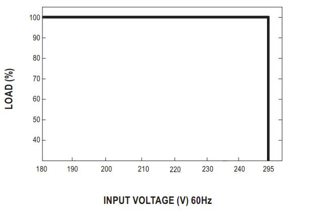
| INPUT | VOLTAGE RANGE Note2 | 180 – 295VAC (Please refer to the “STATIC CHARACTERISTIC” section) |
| FREQUENCY RANGE | 47 – 63Hz | |
| POWER FACTOR (Typ.) | PF:?-.0.95/230VAC@Ioad:?:50%; PF7=:0.9/277VAC@load := 75% (Please refer to “POWER FACTOR (PF) CHARACTERISTIC” section) | |
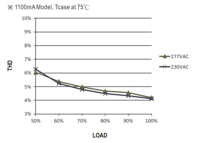
| TOTAL HARMONIC DISTORTION | THD< 10%(@load?.50%/230VAC; @load.475%/277VAC) (Please refer to ‘TOTAL HARMONIC DISTORTION (THD)” section) | |
| EFFICIENCY gyp.) Note.6 | 90%(230VAC@Full load) | |
| AC CURRENT gyp.) | 0.35A/ 230VAC 0.25A/ 277VAC | |
| INRUSH CURRENTgyp.) | COLD START 30A(twidth=300ps measured at 50% Speak)/230VAC; Per NEMA 410 | |
| MAX. No. of PSUs on 16A CIRCUIT BREAKER | 17 units (circuit breaker of type B) / 29 units (circuit breaker of type C) at 230VAC | |
| LEAKAGE CURRENT | <0.75mA / 277VAC | |
| PROTECTION | SHORT CIRCUIT | Hiccup mode or constant current limiting, recovers automatically after the fault condition is removed |
| OVER VOLTAGE | 61 – 80V | |
| Shut down o/p voltage with auto-recovery or re-power on to recovery | ||
| OVER TEMPERATURE | Shut down o/p voltage, with auto-recovery | |
| FUNCTION | DIMMING | Please refer to the “DIMMING OPERATION” section |
| TEMP. COMPENSATION | By external NTC, please refer to the “TEMPERATURE COMPENSATION OPERATION” section | |
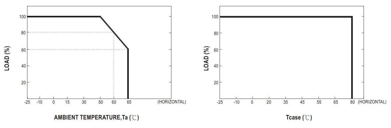
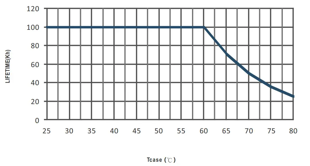
| ENVIRONMENT | WORKING TEMP. | Maser-25 – +80t (Please refer to ‘OUTPUT LOAD vs TEMPERATURE” section) |
| MAX. CASE TEMP. | Tcase.+80 C | |
| WORKING HUMIDITY | 20 – 95% RH non-condensing | |
| STORAGE TEMP., HUMIDITY | -40 – 4-80’C, 10 – 95% RH | |
| TEMP. COEFFICIENT | ±0.03%/°C (0 – 60°C) | |
| VIBRATION | 10 – 500Hz, 2G 10min/1cycle, period for 60min. each along X, Y, Z axes | |
| SAFETY & EMC | SAFETY STANDARDS Notes | UL8750, CSA C22.2 No. 250.13-12; ENEC BS EN/EN61347-1, BS EN/EN61347-2-13, AS/NZS 61347.1, AS/NZS IEC 61347.2.13; BS EN/EN62384; GB19510.14,GB19510.1, EAC TP TC 004, BIS IS15885 approved |
| DALI STANDARDS | Compliance to IEC62386-101.102.207 for DA-Type only | |
| WITHSTAND VOLTAGE | UP-0/P:3.75KVAC UP-FG:2.0KVAC 0/P-FG:1.5KVAC | |
| ISOLATION RESISTANCE | I/P-0/P, UP-FG, 0/P-FG:100M Ohms / 500VDC / 25t/ 70% RH | |
| EMC EMISSION Note.5 | Compliance to BS EN/EN55015,BS EN/EN61000-3-2 Class C (@load•—= 50%) ; BS EN/EN61000-3-3;GB/T17743, GB17625.1,EAC TP TC 020 | |
| EMC IMMUNITY | Compliance to BS EN/EN61000-4-2,3,4,5,6,8,11; BS EN/EN61547, light industry level (surge immunity:Line-Earth: 2KV,Line-Line:1KV),EAC TP TC 020 | |
| OTHERS | MTBF | 2521K hrs min. Telcordia SR-332 (Bellcore) 226.1Khrs min. MIL-HDBK-217F (25°C) |
| DIMENSION | 320*30*21mm (LAW*H) | |
| PACKING | 0.255Kg;48pcs/13.24Kg/0.92CUFT | |
| NOTE | 1. All parameters NOT specially mentioned are measured at 230VAC input, rated current, and 25°C of ambient temperature. 2. Please refer to ” OUTPUT CURRENT SETTING ”. 3. De-rating may be needed under low input voltages. Please refer to the “STATIC CHARACTERISTIC” sections for details. 4. Length of setup time is measured at first cold start. Turning ON/OFF the power supply may lead to an increase of the setup time. 5. The driver is considered as a component that will be operated in combination with final equipment. Since EMC performance will be affected by the complete installation, the final equipment manufacturers must re-qualify EMC Directive on the complete installation again. 6. The DA-type power supply is less efficient than the typical efficiency in specification by 2%. 7. This series meets the typical life expectancy of >50000 hours of operation when Tcase, particularly (te) point (or TMP, per DLC), is about 70°C or less. 8. Please refer to the warranty statement on MEAN WELL’s website at http:/Awww.meanwell.com. 9. The ambient temperature derating of 3.5°C/1000m with fanless models and of 5°C/1000m with fan models for operating altitudes higher than 2000m(6500ft). 10. To fulfill the requirements of the latest ErP regulation for lighting fixtures, this LED power supply can only be used behind a switch without being permanently connected to the mains. Product Liability Disclaimer: For detailed information, please refer to https://Avwww.meanwell.com/serviceDisclaimer.aspx | |
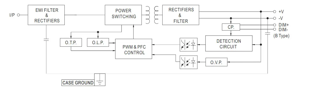
BLOCK DIAGRAM
OUTPUT CURRENT SETTING
- I-V Operating Area.
Output rated current level can be adjusted by an additive resistance.
- Rated current setting table
18K 20K 24K 27K 30K 33K 36K 39K 43K 47K 56K 68K 91K 150K 200K NC 1.6A 1.52A 1.45A 1.32A 1.26A 1.2A 1.15A 1.11A 1.06A 1.03A 0.95A 0.88A 0.8A 0.7A 0.65A 0.5A
DIMMING OPERATION
3 in 1 dimming function(for B-Type)
- Output constant current level can be adjusted by applying one of the three methodologies between DIM+ and DIM-: 0 ~ 10VDC, or 10V PWM signal or resistance.
- Direct connecting to LEDs is suggested. It is not suitable to be used with additional drivers.
- Dimming source current from power supply: 100 A (typ.)
Applying additive 0 ~ 10VDC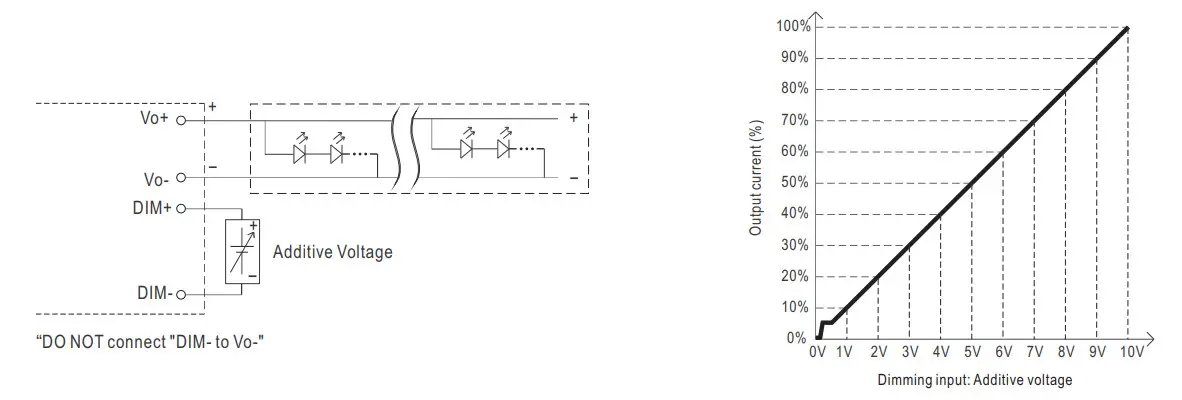
Applying additive 10V PWM signal (frequency range 100Hz ~ 3KHz):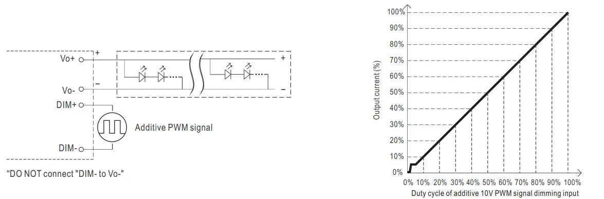
Applying additive resistance: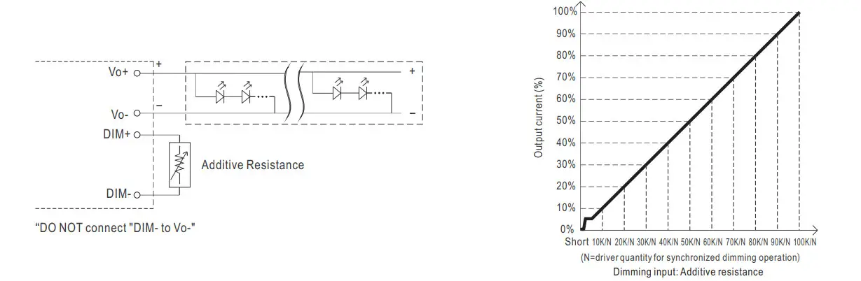
Note :
- Min. dimming level is about 8% and the output current is not defined when 0%< out<8%.
- The output current could drop down to 0% when dimming input is about 0Vdc or 10V PWM signal with a 0% duty cycle.
- To ensure the dimming performance at a low dimming level, the output current must be over 75mA.
DALI interface
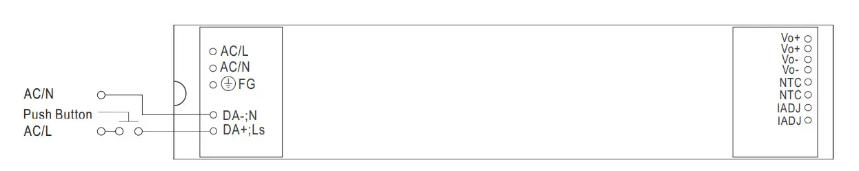
PUSH dimming(primary side)
| Action | Action duration | Function |
| Short push | 0.1-1 sec. | Turn ON-OFF the driver |
| Long push | 1.5-10 sec. | Every Long Push changes the dimming direction, dimming up or down |
| Reset | >11 sec. | Set up the dimming level to 100% |
- The factory default dimming level is at 100%.
- If the push action lasts less than 0.05 sec., it will not lead to a change for the status of the driver.
- Up to 10 drivers can perform the PUSH dimming at the same time when utilizing one common push button.
- The maximum length of the cable from the push button to the last driver is 20 meters.
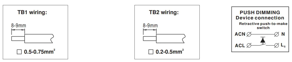
- The additive push button can be connected only between the LS terminal, as displayed in the diagram, and AC/L (in brown or black); it will lead to short circuit if it is connected to AC/N.
DALI interface(primary side)
- Apply DALI signal between DA+ and DA-
- DALI protocol comprises 16 groups and 64 addresses.
- First step is fixed at 8% of rated output power.
NOTE: DALI, Push dimming can not be used in the same time!(The factory setting defaults to DA)
TEMPERATURE COMPENSATION OPERATION
LDC-55 have the built-in temperature compensation function ; by connecting a temperature sensor (NTC terminal) between the +NTC / -NTC terminal of LDC-55 and the detecting point on the lighting system or the surrounding environment, output current of LDC-55 could be correspondingly changed, based on the sensed temperature, to ensure the long life of LED.
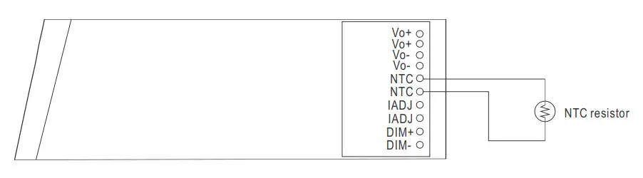
- LDC-55 can still be operated normally when the NTC resistor is not connected and the value of output current will be the current level selected through the IADJ. pin
- NTC reference:
| NTC resistance | Output Current |
| <33K | Output current reduces as the resistance decreases |
| >33K | Normal output current |
Notes:
- MEAN WELL does not offer the NTC resistor and all the data above are measured by using a resistor.
- If the new brand of NTC resistor is applied, please check the temperature curve first.
Dimming function of the driver will be invalid when the “temperature compensation” function is in use.
OUTPUT LOAD vs TEMPERATURE
STATIC CHARACTERISTIC
POWER FACTOR (PF) CHARACTERISTIC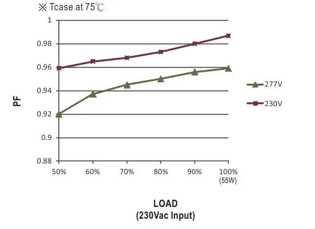
TOTAL HARMONIC DISTORTION (THD)
EFFICIENCY vs LOAD
LDC-55 series possess superior working efficiency up to 90%.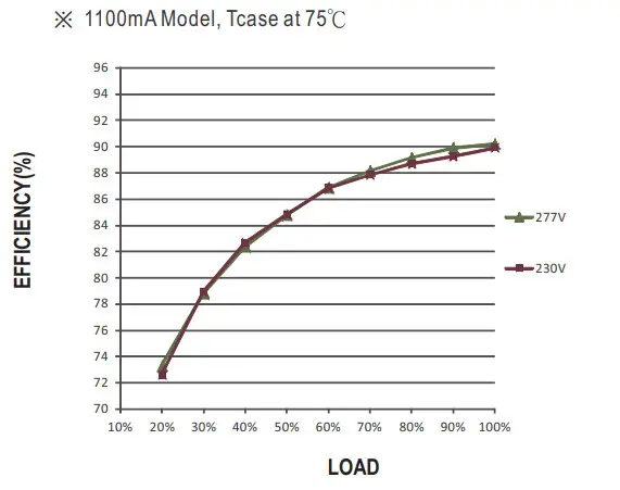
EFFICIENCY vs LOAD
LDC-55 series possess superior working efficiency up to 90%.
1100mA Model, Tcase at 75℃
LIFETIME
MECHANICAL SPECIFICATION
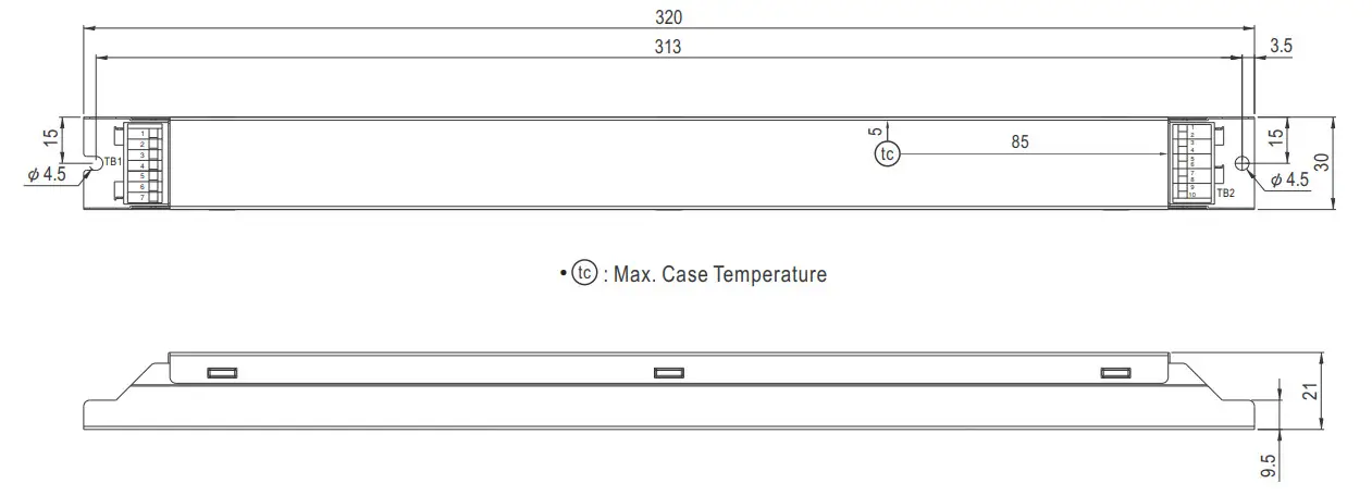
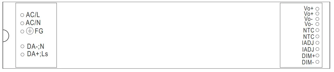
Terminal Pin No. Assignment (TB1) :
| Pin No. | Assignment |
| 1 | ACL |
| 2 | ACNE |
| 3 | NC |
| 4 | FG |
| 5 | NC(for DA-type only ) |
| 6 | DA-/N(for DA-type only) |
| 7 | DA+/Ls(for DA-type only) |
Terminal Pin No. Assignment (TB2) :
| Pin No. | Assignment |
| 1 | Vo+ |
| 2 | Vo+ |
| 3 | Vo- |
| 4 | Vo- |
| 5 | NTC |
| 6 | NTC |
| 7 | IADJ |
| 8 | IADJ |
| 9 | DIM+(for B-type only) |
| 10 | DIM-(for B-type only) |
Installation Manual
Please refer to : http://www.meanwell.com/manual.html


