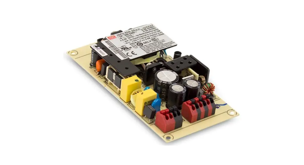
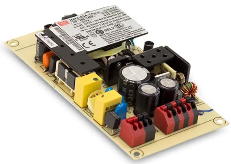
![]() 65W PWM Output LED Driver
65W PWM Output LED Driver
I D P V- 6 5 series
http://www.meanwell.com.cn/Upload/PDF/LED_EN.pdf
Features
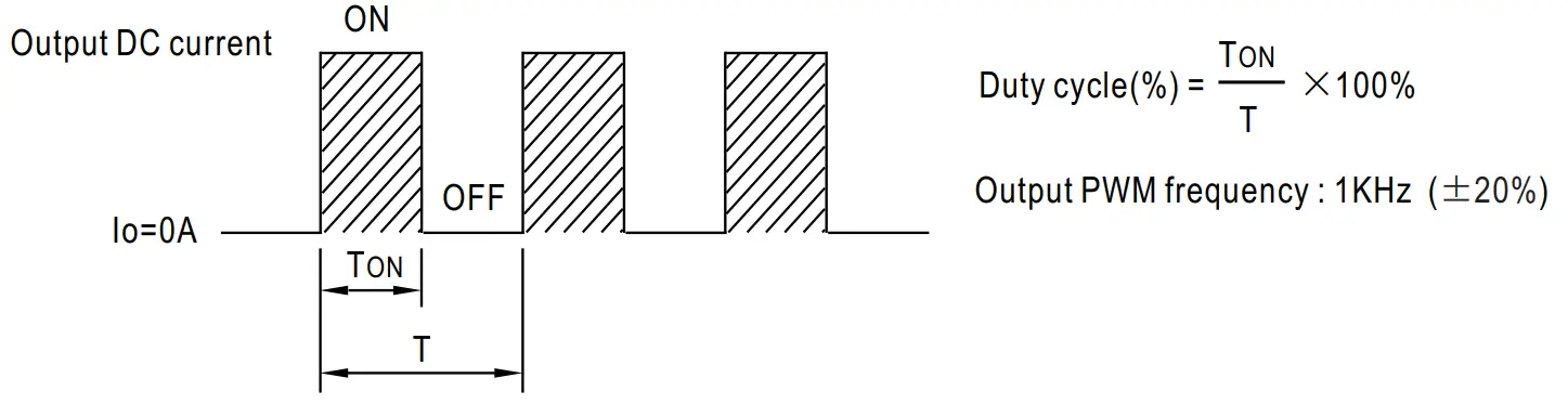
- Constant Voltage PWM style output with frequency 1 KHz
- PCB type design
- Built-in active PFC function
- No load power consumption<0.5W
- Function options: 2 in 1 dimming (dim-to-off); Auxiliary DC output
- 3 years warranty
Applications
- LED strip lighting
- Indoor LED lighting
- LED decorative lighting
- LED architecture lighting
GTIN CODE
MW Search. haps://www.meanwell.corniserviceGTIN.aspx
Description
IDPV-65 series is a 65W PCB type AC/DC LED driver featuring the constant voltage mode PWM style output design. IDPV-65 operates from 180-295VAC and offers models with different rated voltages ranging between 12V and 60V. Thanks to the high efficiency of up to 90%, with the fanless design, the entire series is able to operate for -20 C-+40 C ambient temperature under free air convection. IDPV-65 is equipped with various function options, such as dimming methodologies, so as to provide design flexibility for the LED lighting systems.
Model Encoding
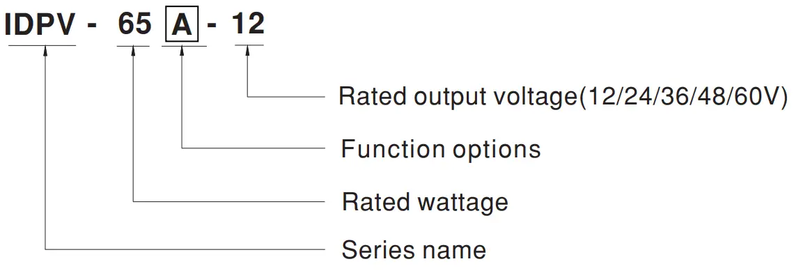
| Type | Function |
| Blank | 2 in 1 dimming (0-10VDC and 10V PWM) |
| A | 2 in 1 dimming and Auxiliary DC output |
SPECIFICATION
| MODEL | IDPV-650-12 | ippv.650-24 | DPV-6036 | IDPV-6C-48 | IDPV-61:1-60 | |||||
| OUTPUT | DC VOLTAGE | 12V | 24V | 36V | 48V | 60V | ||||
| RATED CURRENT | 4.2A | 2.4A | 1.8A | 1.35A | 1.08A | |||||
| RATED POWER | 50.4W | 57.6W | 64.8W | 64.8W | 64.8W | |||||
| DIMMING RANGE | 0-100% | |||||||||
| VOLTAGE TOLERANCE | ± 10% | |||||||||
| PWM FREQUENCY (Typ.) | 1KFtz(± 20%) | |||||||||
| SETUP TIME Note.3 | 500ms /230VAC | |||||||||
| AUXILIARY DC OUTPUT Nob/ | Nominal 12V(deviation 11.4-12.6)@50mA forA-Type only | |||||||||
| INPUT | VOLTAGE RANGE Note.2 | 180 – 295VAC 254 – 417VDC (Please refer to ‘STATIC CHARACTERISTIC’ section) | ||||||||
| FREQUENCY RANGE | 47 – 63Hz | |||||||||
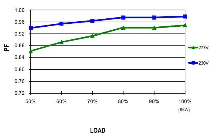
| POWER FACTOR crypt.) | PF>0.95/230VAC, PF>0.9/277VAC@ifull load (Please refer to the ‘POWER FACTOR (PF) CHARACTERISTIC’ section) | |||||||||
| TOTAL HARMONIC DISTORTION | THD< 20%(@loadM0%/230VAC; @load.475%/277VAC) (Please refer to “TOTAL HARMONIC DISTORTION’ section) | |||||||||
| EFFICIENCY (Typ.) | 85% | I87% | I88% | I89% | I90% | |||||
| AC CURRENT (Typ.) | 0.4A/230VAC 0.3A/277VAC | |||||||||
| INRUSH CURRENT(Typ.) | COLD START 30A(twidth=270ps measured at 50% (peak) at 230VAC: Per NEMA 410 | |||||||||
| MAX. No. of PSUs on 16A CIRCUIT BREAKER | 32 units (circuit breaker of type B)/ 32 units (circuit breaker of type C) at 230VAC | |||||||||
| LEAKAGE CURRENT | <0.75mA/ 277VAC | |||||||||
| NO LOAD POWER CONSUMPTION | <0.5W | |||||||||
| PROTECTION | SHORT CIRCUIT | Shutdown 0/P voltage, re-power on to recovery | ||||||||
| OVER CURRENT | 105 -115% | |||||||||
| Protection type : Hiccup mode, recovers automatically after fault condition is removed | ||||||||||
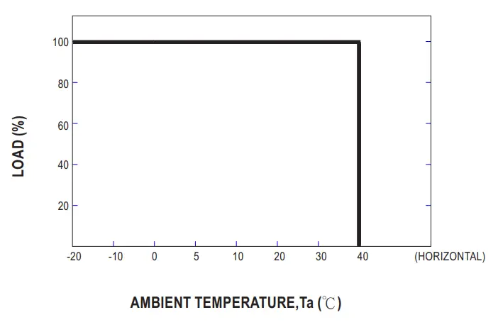
| ENVIRONMENT | WORKING TEMP. | Ta=-20 – +40 C (Please refer to” OUTPUT LOAD vs TEMPERATURE’ section) | ||||||||
| WORKING HUMIDITY | 20 – 90% RH non-condensing | |||||||||
| STORAGE TEMP., HUMIDITY | -40 – +80°C, 10 – 95% RH | |||||||||
| TEMP. COEFFICIENT | ±0.03%/C (0 – 40°C) | |||||||||
| VIBRATION | 10 – 500Hz, 2G 10min./Tricycle, period for 60min . each along X. Y. Z axes | |||||||||
| SAFETY & EMC | SAFETY STANDARDS | UL8750.CSA C22.2 NO.250.13-12;ENEC EIS EN/ EN61347-1 & BS EN!EN61347-2-13 independent, BS EN!EN62384approved | ||||||||
| WITHSTAND VOLTAGE | I/P-0/P:3.75KVAC | |||||||||
| ISOLATION RESISTANCE | I/P-0/P:100M Ohms / 500VDC / 25°Ci 70% RH | |||||||||
| EMC EMISSION | Compliance to BS E N/E N55015, BS E N/EN61000-3-2 Class C (tRbad:=60%); BS EN/EN61000-3-3 | |||||||||
| EMC IMMUNITY | Compliance to BS EN/EN61000-4-2,3,4,5,6,8,11; BS EN/EN61547.1ight industry level(surge immunity: Lthe-Line:1KV) | |||||||||
| OTHERS | MTBF | 3720.1K hrs min. Telcordia SR-332 (Bellcore); 398.8K hrs min. MIL-HDBK-217F (25°C) | ||||||||
| DIMENSION | 130’67.5’22mm (L’IN*F1) | |||||||||
| PACKING | 0.15Kg;81pcs/13Kg/ 1.46CUFT | |||||||||
| NOTE | 1. All parameters NOT specially mentioned we measured at 230VAC input, rated current, and 25’C of ambient temperature. 2. Deleting may be needed under low input voltages. Please refer to b ‘STATIC CHARACTERISTIC’ sections tar details. 3. Length of setup time is measured at cold first start. Turning OWOFF the driver may lead to an increase in the setup time. 4. Aux. 12V will be damaged with a short circuit It will not be available with dimming off or output no load condition. 5. The (liver is considered a component that a be operated in combination with final equipment Since EMC performance will be affected by the complete installation. the final equipment manufacturers must requalify EMC Directive on the complete installation again. ※ Product Liability Disclaimer: For detailed information, please refer to https://www.meamwell.con/servicedisclaimer.aspx | |||||||||
DIMMING OPERATION
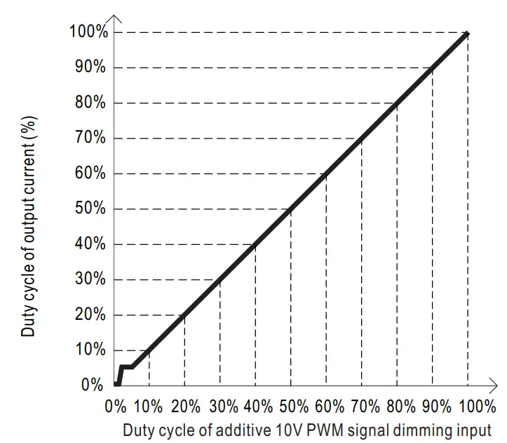
※ Dimming principle for PWM style output
- Dimming is achieved by varying the duty cycle of the output current.
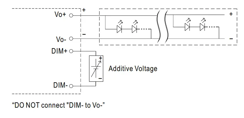
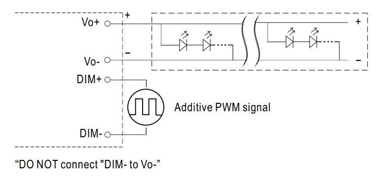
※ 2 in 1 dimming function
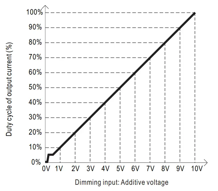
◎ Applying additive 0 ~ 10VDC
◎ Applying additive 10V PWM signal (frequency range 300Hz~3KHz):
 |  |
Note
- Min. duty cycle of output current is about 8% and the output current is not defined when 0%< Iout<8%.
- The duty cycle of output current could drop down to 0% when dimming input is about 0Vdc or 10V PWM signal with 0% duty cycle.
- To ensure the dimming effect, total power must be over 45W at 100% duty cycle.
OUTPUT LOAD vs TEMPERATURE
STATIC CHARACTERISTIC
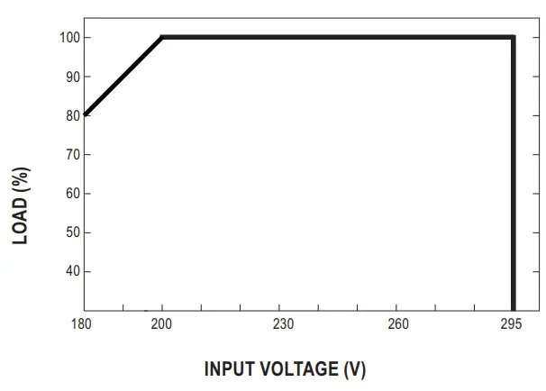
※ De-rating is needed under low input voltage.
POWER FACTOR (PF) CHARACTERISTIC
TOTAL HARMONIC DISTORTION (THD)
※ 60V Model
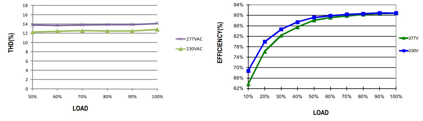
EFFICIENCY vs LOAD
IDPV-65 series possess superior working efficiency that up to 90% can be reached in field applications.
※ 60V Model
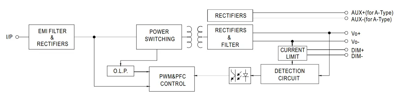
BLOCK DIAGRAM
fosc : 70-150KHz
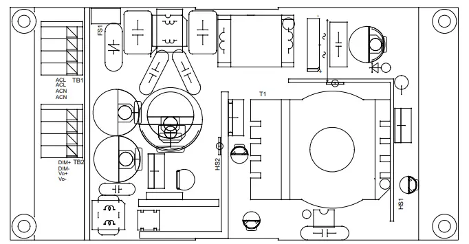
MECHANICAL SPECIFICATION
※ Blank-Type
Unit:mm
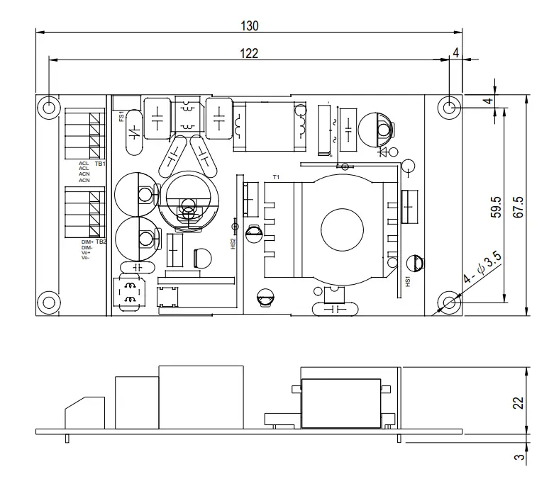
Terminal Pin No. Assignment(TB1)
| Pin No. | Assignment |
| 1 | ACL |
| 2 | ACL |
| 3 | ACN |
| 4 | ACN |
Terminal Pin No. Assignment(TB2)
| Pin No. | Assignment |
| 1 | DIM+ |
| 2 | DIM- |
| 3 | Vo+ |
| 4 | Vo- |
※ A-Type
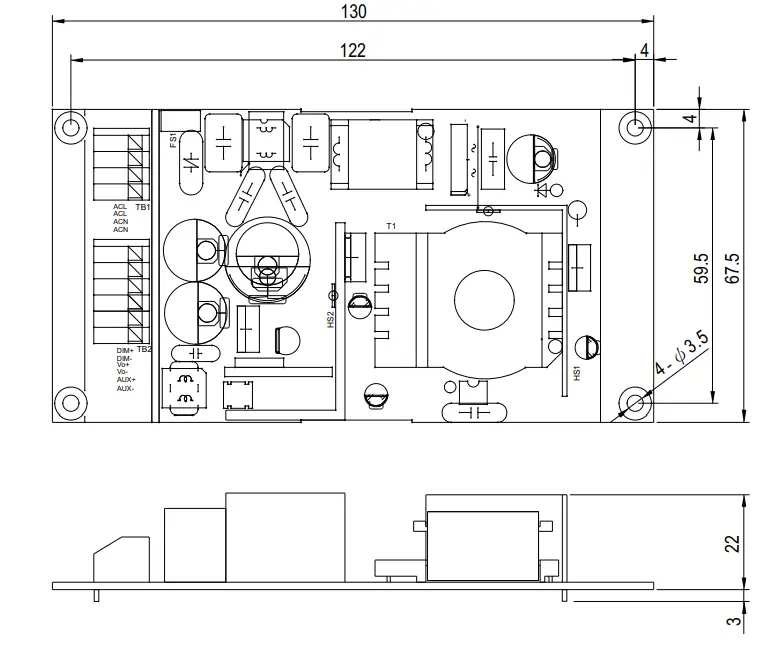
Terminal Pin No. Assignment(TB1)
| Pin No. | Assignment |
| 1 | ACL |
| 2 | ACL |
| 3 | ACN |
| 4 | ACN |
Terminal Pin No. Assignment(TB2)
| Pin No. | Assignment | Pin No. | Assignment |
| 1 | DIM+ | 4 | Vo- |
| 2 | DIM- | 5 | AUX+ |
| 3 | Vo+ | 6 | AUX |
INSTALLATION MANUAL
Please refer to: http://www.meanwell.com/manual.html
File Name:IDPV-65-SPEC 2022-02-18![]()


