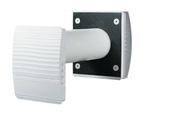
VENTS 53-115 TwinFresh Expert RW-30 V.2 Single Room Ventilation System
PURPOSE
This guide covers the connection of TwinFresh Expert RW V.2 (V.3) and TwinFresh Style Wi-Fi series of air handling units to a “Smart House” system.
Control is provided only by Master devices. Slave devices, mobile devices, and “Smart House” system components are connected to master devices over Wi-Fi. Slave devices are controlled by means of commands received from master devices.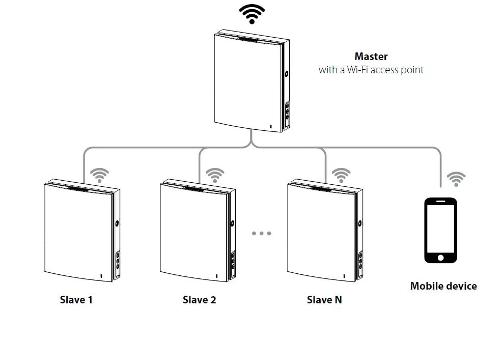
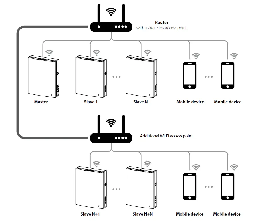
There are two wireless connection patterns available:
- A master device with a Wi-Fi access point, which can accept up to eight slave connections. If all available eight connections of the master device are used, a mobile device or a “Smart House” system will not be able to connect to the master device.
- Master devices, slave devices, mobile devices and a “Smart House” system connect to the Wi-Fi access point of the network router. In this case, the maximum number of available Wi-Fi connections is limited by the router functionality. If the number of necessary ventilation units is more than the router can accept, you may use an additional Wi-Fi access point to connect the remaining ventilation units. The router network may include several master devices to provide control by zones.
The connection is set up via the mobile application from the Connection – > Wi-Fi setup menu (see the unit data sheet).
NETWORK PARAMETERS
Data is exchanged via the UDP protocol (with broadcast support).
Master device IP address:
- 192.168.4.1 – if the master device runs without a router (connection pattern 1).
- If the master device is connected via a router (connection pattern 2), the IP address is set up via the mobile application (see unit data sheet) and can be defined as static or dynamic (DHCP).
- Master device port: 4000.
- Maximum packet size: 256 bytes.
PACKET STRUCTURE


- protocol type (1 byte). Value = 0x02.
- ID block size (1 byte). Value = 0x10.
- controller ID. This number is printed on the label (16 characters) applied to the control circuit board or the unit casing.
You can also substitute the ID with “DEFAULT_DEVICEID” code word. The ID can be used:
- To control the master device if it runs without a router (connection pattern 1).
- To search for master devices on the network if a router is used (connection pattern 2). In this case, the device will respond to two parameters only: 0x007C and 0x00B9 (see parameter table).
 PWD block size (1 byte). Possible values: from 0x00 to 0x08.
 device password (permissible characters: “0…9”, “a…z”, and “A…Z”). The default password is “1111”.
This password can be changed via the mobile application from the Connection –> At home –> Settings menu (see the unit data sheet).
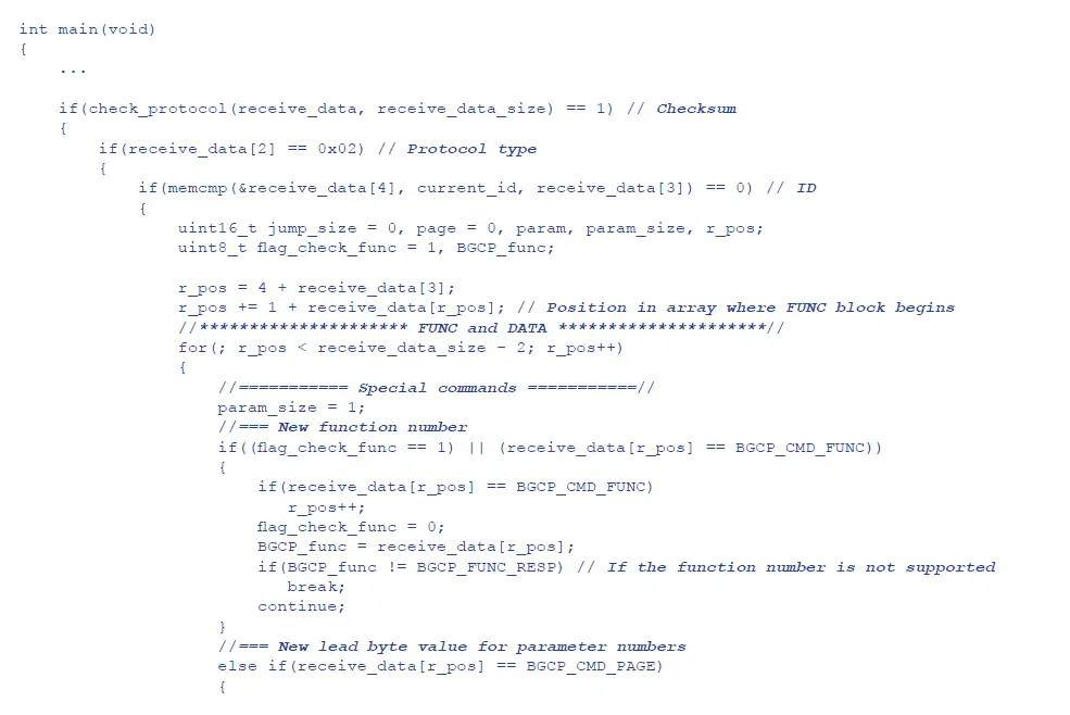
 the function number (1 byte). It defines the action with the data and the DATA block structure:
- 0x01: parameter read.
0x02: parameter write. The controller does not send any response regarding the status of the given parameters. - 0x03: parameter write with subsequent controller response regarding the status of the given parameters.
- 0x04: parameter increment with subsequent controller response regarding the status of the given parameters.
- 0x05: parameter decrement with subsequent controller response regarding the status of the given parameters.
- 0x06: controller response to the request (FUNC = 0x01, 0x03, 0x04, 0x05).
- 0x01: parameter read.
 data block. It consists of parameter numbers and their values:
 the function number (1 byte). It defines the action with the data and the DATA block structure:
 data block. It consists of parameter numbers and their values:
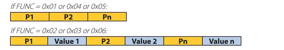
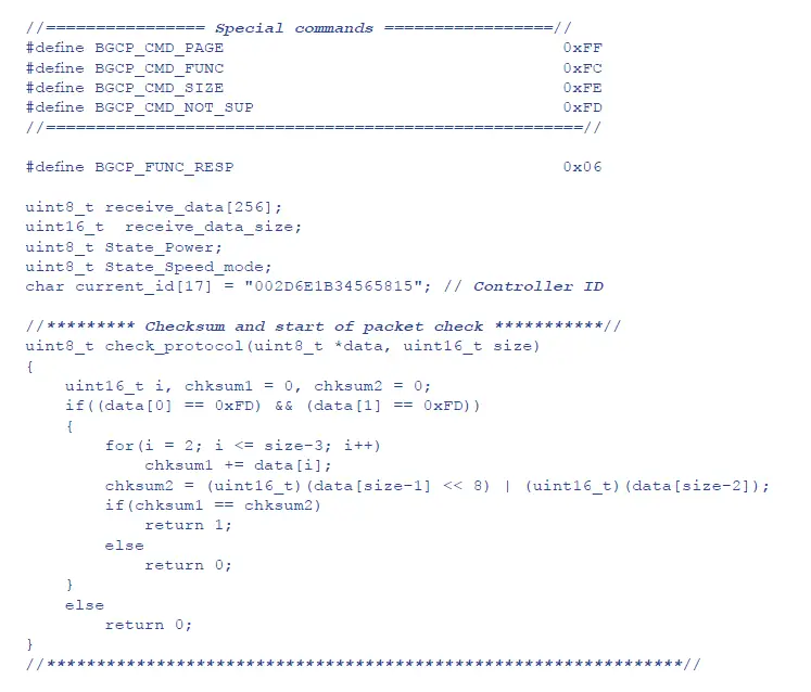
Parameter numbers (see parameter table) consists of two bytes (the high byte is virtual). By default the high byte of each parameter number in each new packet equals 0x00. The high byte can be changed within a single packet using the special 0xFF command (see below).
![]() is the low byte of the parameter number. Possible values: 0x00 – 0xFB. The 0xFC – 0xFF values are special commands:
is the low byte of the parameter number. Possible values: 0x00 – 0xFB. The 0xFC – 0xFF values are special commands:
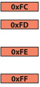
- change function (FUNC) number. The following byte must be the new function number ranging from 0x01 to 0x05. This command is used to organise several functions with different actions into a single packet.
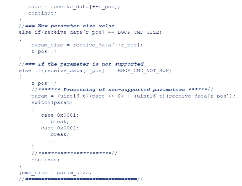
- parameter not supported by the controller. The following byte is the low byte of the non-supported parameter. This command is used in controller response (FUNC = 0x06) to a non-supported parameter read or write request.
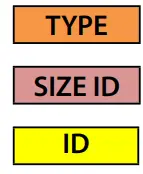
- change a size of the Value for one parameter which follows. The following byte must be the new parameter size followed by the low byte of the parameter number, and then – by the Value itself.
- change the high byte for parameter numbers within a single packet. The following byte must be the new high byte.
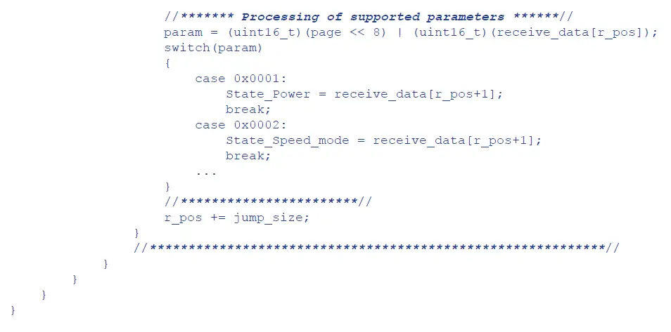
 parameter value (the default size of value is 1 byte). Byte ordering from least significant byte to most significant byte.
 checksum (2 bytes). This is calculated as the total of bytes beginning with the TYPE byte and ending with the final byte of the DATA block.
- Chksum L: checksum low byte.
- Chksum H: checksum high byte.
EXAMPLES OF USING SPECIAL COMMANDS IN THE DATA BLOCK
Write request (FUNC = 0x03) for parameters number 0x009B, 0x0070, and 0x0007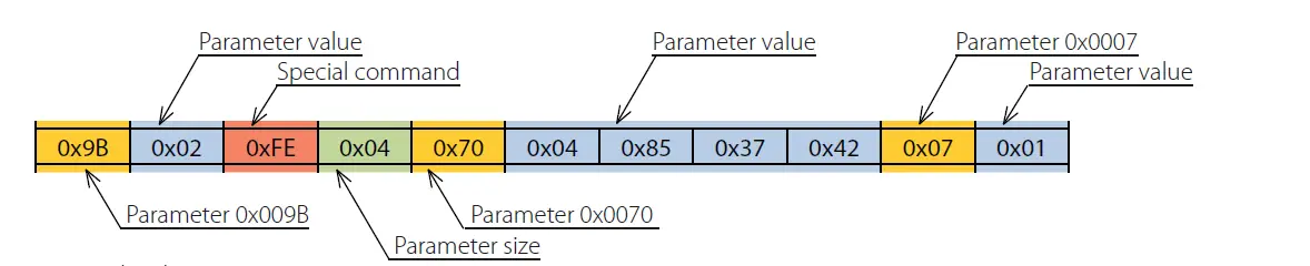
Write request details:
- Parameter 0x009B to be assigned the value of 0x02.
- Parameter 0x0070 to be assigned the value of 0x42378504. The value size is 4 bytes as indicated by the special command 0xFE + 0x04.
- Parameter 0x0007 to be assigned the value of 0x01.
Controller response (FUNC = 0x06) to write request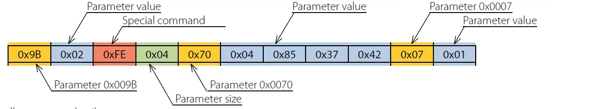
Controller response details
- Parameter 0x009B equals 0x02.
- Parameter 0x0070 equals 0x42378504. The value size is 4 bytes as indicated by the special command 0xFE + 0x04.
- Parameter 0x0007 equals 0x01.
Read request (FUNC = 0x01) for parameters number 0x0101, 0x0104, and 0x0240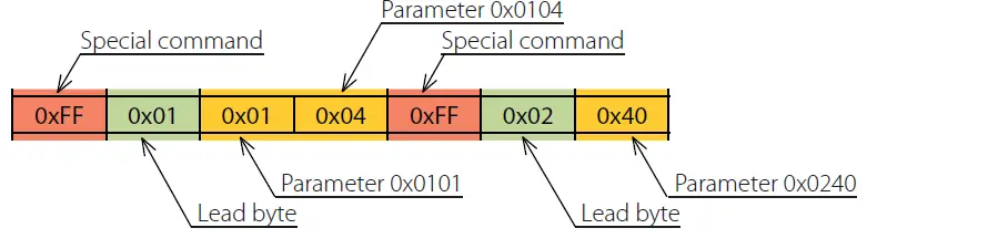
Controller response details:
- Parameter 0x009B equals 0x02.
- Parameter 0x0070 equals 0x42378504. The value size is 4 bytes as indicated by the special command 0xFE + 0x04.
- Parameter 0x0007 equals 0x01.
Read request (FUNC = 0x01) for parameters number 0x0101, 0x0104, and 0x0240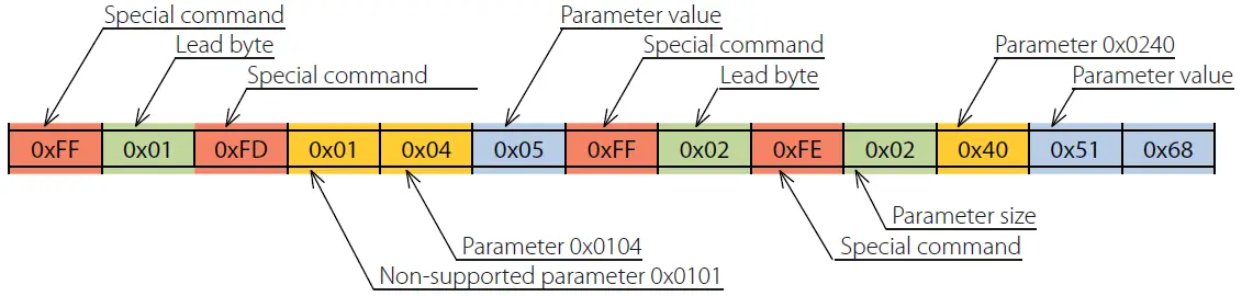
Controller response (FUNC = 0x06) to write request
Controller response details:
- Parameter 0x0101 is not supported by the controller as indicated by the special command 0xFD.
- Parameter 0x0104 equals 0x05.
- Parameter 0x0240 equals 0x6851. The value size is 2 bytes as indicated by the special command 0xFE + 0x02.
COMPLETE PACKET EXAMPLES
Sending “Smart House–> Controller” packet
This packet contains a read request (FUNC = 0x01) for parameters number: 0x0001, 0x0002.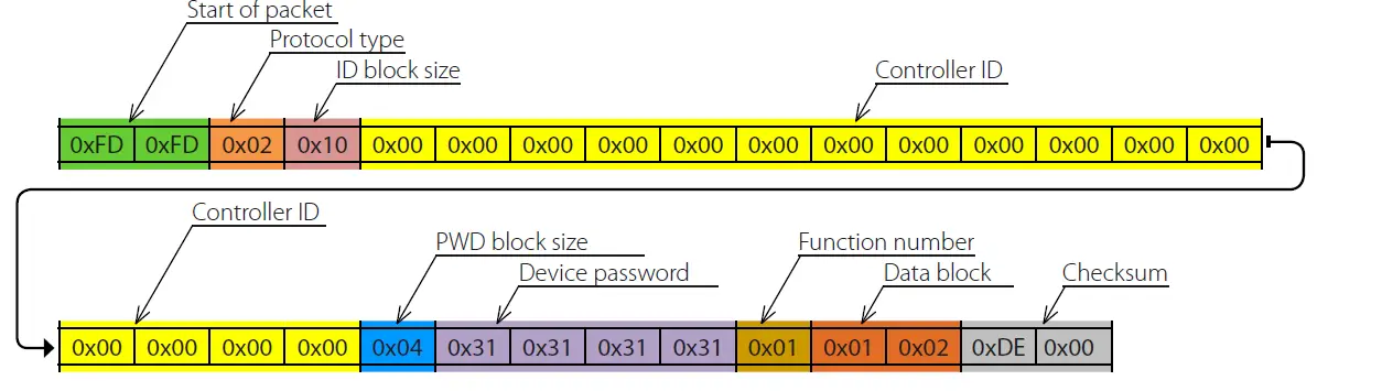
Sending “Controller –> Smart House” packet
This packet contains the controller response (FUNC = 0x06) to the write request.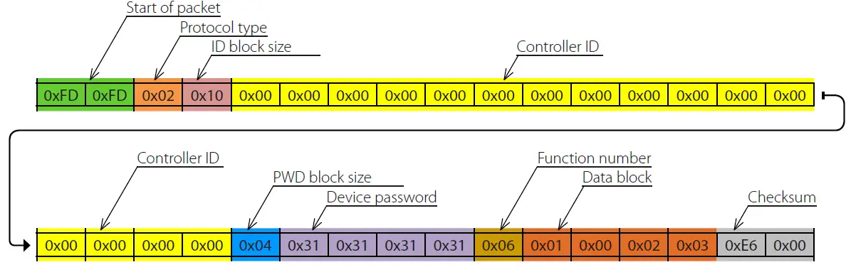
Controller response details:
- Parameter 0x0001 equals 0x00.
- Parameter 0x0002 equals 0x03.
- Checksum: 0x00E6.
PARAMETER TABLE
Functions
- R – 0x01
- INC – 0x04
- RW – 0x03
- W – 0x02
- DEC – 0x05
| Parameter number [Dec./Hex.] | Functions | Description | Possible values | Size [bytes] |
| 1/0x0001 | R/W/RW | Unit On/Off | 0 — Off 1 — On 2 – Invert | 1 |
| 2/0x0002 | R/W/RW/INC/DEC | Speed number | 1 – Speed 1 2 – Speed 2 3 – Speed 3 255 – manual speed setting mode (see parameter 68) | 1 |
| 6/0x0006 | R | Boost mode status | 0 – Off 1 – On | 1 |
| 7/0x0007 | R/W/RW/INC/DEC | Timer mode (see parameters 770 and 771) | 0 – Off 1 – Night mode 2 – Party mode | 1 |
| 11/0x000B | R | Current countdown of the Timer mode | Byte 1 – seconds (0…59) Byte 2 – minutes (0…59) Byte 3 – hours (0…23) | 3 |
| 15/0x000F | R/W/RW | Humidity sensor activation | 0 – Off 1 – On 2 – Invert | 1 |
| 20/0x0014 | R/W/RW | Relay sensor activation | 0 – Off 1 – On 2 – Invert | 1 |
| 22/0x0016 | R/W/RW | 0–10 V* sensor activation | 0 – Off 1 – On 2 – Invert | 1 |
| 25/0x0019 | R/W/RW/INC/DEC | Humidity threshold setpoint | 40…80 RH% | 1 |
| 36/0x0024 | R | Current RTC battery voltage | 0…5000 mV | 2 |
| 37/0x0025 | R | Current humidity | 0…100 RH% | 1 |
| 45/0x002D | R | Current 0–10 V* sensor signal value | 0…100 % | 1 |
| 50/0x0032 | R | Current relay sensor state | 0 – Off 1 – On | 1 |
| 58/0x003A | R/W/RW/INC/DEC | Supply fan speed in 1st speed mode** | 10…255 | 1 |
| 59/0x003B | R/W/RW/INC/DEC | Exhaust fan speed in 1st speed mode** | 10…255 | 1 |
| 60/0x003C | R/W/RW/INC/DEC | Supply fan speed in 2nd speed mode** | 10…255 | 1 |
| 61/0x003D | R/W/RW/INC/DEC | Exhaust fan speed in 2nd speed mode** | 10…255 | 1 |
| 62/0x003E | R/W/RW/INC/DEC | Supply fan speed in 3rd speed mode** | 10…255 | 1 |
| 63/0x003F | R/W/RW/INC/DEC | Exhaust fan speed in 3rd speed mode** | 10…255 | 1 |
| 74/0x004A | R | Fan 1 speed | 0…5000 rpm | 2 |
| 75/0x004B | R | Fan 2 speed | 0…5000 rpm | 2 |
| 99/0x0063 | R/W/RW/INC/DEC | Filter replacement timer setup** | 70…365 days | 2 |
| 100/0x0064 | R | Timer countdown to filter replacement | Byte 1 – minutes (0…59) Byte 2 – hours (0…23) Byte 3 – days (0…181) | 3 |
| Parameter number [Dec./Hex.] | Functions | Description | Possible values | Size [bytes] |
| 101/0x0065 | W | Reset timer countdown to filter replacement | Any byte | 1 |
| 102/0x0066 | R/W/RW/INC/DEC | Setpoint of the Boost mode deactivation delay | 0…60 minutes | 1 |
| 111/0x006F | R/W/RW | RTC time | Byte 1 – RTC seconds (0…59) Byte 2 – RTC minutes (0…59) Byte 3 – RTC hours (0…23) | 3 |
| 112/0x0070 | R/W/RW | RTC calendar | Byte 1 – RTC number (1…31) Byte 2 – RTC day of the week (1…7) Byte 3 – RTC month (1…12) Byte 4 – RTC year (0…99) | 4 |
| 114/0x0072 | R/W/RW | Weekly schedule mode | 0 — Off 1 — On 2 – Invert | 1 |
| Schedule setup | Byte 1 – day of the week: 0 – all days (write only) 1 – Monday 2 – Tuesday 3 – Wednesday 4 – Thursday 5 – Friday 6 – Saturday 7 – Sunday 8 – Mon…Fri (write only) 9 – Sat…Sun (write only) Byte 2 – period number: 1…4 Byte 3 – speed number: 0 – standby 1…3 Byte 4 – reserved: any byte Byte 5 – minutes to end of period: 0…59 Byte 6 – hours to end of period: 0…23 | |||
| In the read request you should use | ||||
| special command 0xFE and specify | ||||
| the size of the 0x02 parameter value | ||||
| required for selecting the necessary | ||||
| day of the week and time period | ||||
| number. | ||||
| 119/0x0077 | R/W/RW | The write request and the controller | 6 | |
| response use all the 6 bytes. | ||||
| The first time period always starts at | ||||
| 00:00 while the start of each following | ||||
| period begins at the end of the | ||||
| previous one. | ||||
| The final time period always ends at | ||||
| 24:00 | ||||
| 124/0x007C | R | Device search on the local network, ID | Text (“0…9”, “A…F”) | 16 |
| 125/0x007D | R/W/RW | Device password | Text (“0…9”, “a…z”, “A…Z”) | 0–8 |
| 126/0x007E | R | Machine hours | Byte 1 – minutes (0…59) Byte 2 – hours (0…23) Byte 3 and Byte 4 – days (0…65535) | 4 |
| 128/0x0080 | W | Reset alarms | Any byte | 1 |
| 131/0x0083 | R | Alarm/warning indicator | 0 – no 1 – alarm (highest priority) 2 – warning | 1 |
| 133/0x0085 | R/W/RW | Cloud server operation permission | 0 – Off 1 – On 2 – Invert | 1 |
| 134/0x0086 |
R | Controller base firmware version and date | Byte 1 – firmware version (major) Byte 2 – firmware version (minor) Byte 3 – day Byte 4 – month Byte 5 and Byte 6 – year |
6 |
| Parameter number [Dec./Hex.] | Functions | Description | Possible values | Size [bytes] |
| 135/0x0087 | W | Restore factory settings | Any byte | 1 |
| 136/0x0088 | R | Filter replacement indicator | 0 – filter replacement not required 1 – replace filter | 1 |
| 148/0x0094 | R/W/RW/INC/DEC | Wi-Fi operation mode | 1 – Client 2 – Access Point | 1 |
| 149/0x0095 | R/W/RW | Wi-Fi name in Client mode | Text | 1…32 |
| 150/0x0096 | R/W/RW | Wi-Fi password | Text | 8…64 |
| 153/0x0099 | R/W/RW | Wi-Fi data encryption type | 48 – OPEN 50 – WPA_PSK 51 – WPA2_PSK 52 – WPA_WPA2_PSK | 1 |
| 154/0x009A | R/W/RW/INC/DEC | Wi-Fi frequency channel | 1…13 | 1 |
| 155/0x009B | R/W/RW | Wi-Fi module DHCP | 0 – STATIC 1 – DHCP 2 – Invert | 1 |
| 156/0x009C | R/W/RW | IP address assigned to Wi-Fi module | Byte 1 – 0…255, Byte 2 – 0…255, Byte 3 – 0…255, Byte 4 – 0…255 | 4 |
| 157/0x009D | R/W/RW | Wi-Fi module subnet mask | Byte 1 – 0…255, Byte 2 – 0…255, Byte 3 – 0…255, Byte 4 – 0…255 | 4 |
| 158/0x009E | R/W/RW | Wi-Fi module main gateway | Byte 1 – 0…255, Byte 2 – 0…255, Byte 3 – 0…255, Byte 4 – 0…255 | 4 |
| 160/0x00A0 | W | Apply new Wi-Fi parameters and quit Setup Mode | Any byte | 1 |
| 162/0x00A2 | W | Discard new Wi-Fi parameters and quit Setup Mode | Any byte | 1 |
| 163/0x00A3 | R | Current Wi-Fi module IP address | Byte 1 – 0…255, Byte 2 – 0…255, Byte 3 – 0…255, Byte 4 – 0…255 | 4 |
| 183/0x00B7 | R/W/RW/INC/DEC | Ventilator operation mode | 0 – ventilation 1 – heat recovery 2 – supply | 1 |
| 184/0x00B8 | R/W/RW/INC/DEC | 0–10 V* sensor threshold setpoint | 5…100 % | 1 |
| 185/0x00B9 |
R |
Unit type | 3: TwinFresh Expert RW1-50 V.2, TwinFresh Expert RW1-85 V.2, TwinFresh Expert RW1-100 V.2 4: TwinFresh Expert Duo RW1-30 V.2 5: TwinFresh Expert RW-30 V.2 |
2 |
| 252/0x00FC | Special commands | |||
| 253/0x00FD | ||||
| 254/0x00FE | ||||
| 255/0x00FF | ||||
| 770/0x0302 | R/W/RW | Night mode timer setpoint | Byte 1 – minutes (0…59) Byte 2 – hours (0…23) | 2 |
| 771/0x0303 | R/W/RW | Party mode timer setpoint | Byte 1 – minutes (0…59) Byte 2 – hours (0…23) | 2 |
| 772/0x0304 | R | Humidity sensor status | 0 – below setpoint 1 – over setpoint | 1 |
| 773/0x0305 | R | 0–10 V* sensor status | 0 – below setpoint 1 – over setpoint | 1 |
Available for all models except TwinFresh Expert RW-30 V.2
Available for TwinFresh Expert RW1-50 V.3, TwinFresh Style Wi-Fi, TwinFresh Style Wi-Fi Frost, TwinFresh Style Wi-Fi mini.