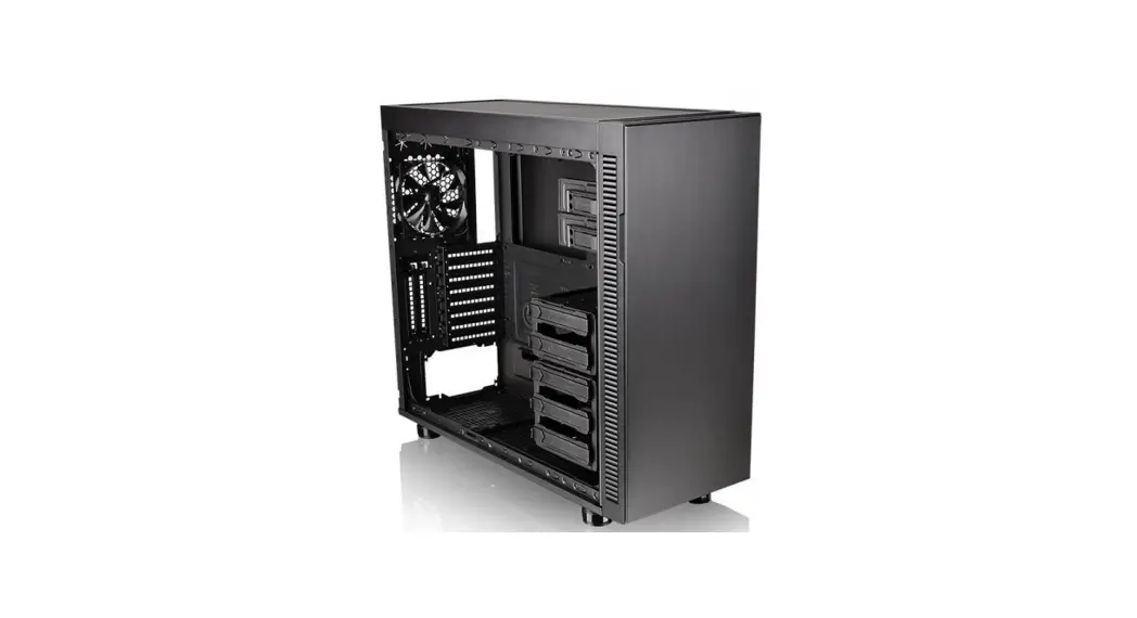
![]() Suppressor F51 Window E-ATX Mid Tower Chassis
Suppressor F51 Window E-ATX Mid Tower Chassis
User Manual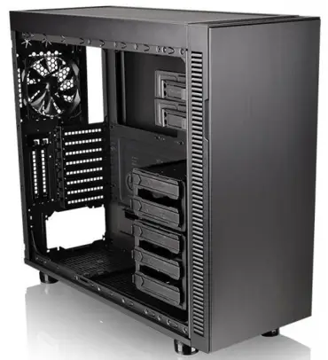
Join Tt Community To Receive Benefits
![]() Dear Valued Customer,
Dear Valued Customer,
Thank you for choosing Thermaltake.
As a new user we value your thoughts and opinions and your feedback is important to us. We at Thermaltake would like to use this opportunity to invite you to join our Community Forums. Register today to start enjoying the full benefits of our community.
Benefits of being a member:
- Quick and responsive user support
- Receive help and advice with new builds
- Keep up to date with new product releases
- Share your thoughts and builds with the community
- Enter monthly contests and giveaways
 http://community.thermaltake.com
Tt LCS-Liquid Cooling Support Certification
Tt LCS Certified is a Thermaltake exclusive certification applied to only products that pass the design and hardcore enthusiasts standards that a true LCS chassis should be held to. The Tt LCS certification was created so that we at Thermaltake can designate to all power users which chassis have been tested to be best compatible with extreme liquid cooling configurations to ensure you get the best performance from the best features and fitment.![]()
Brand official website
http://www.thermaltake.com/
Global Facebook
https://www.facebook.com/ThermaltakeInc
Taiwan Facebook
http://www.facebook.com/ThermaltakeTW
Global community forums
http://community.thermaltake.com
Specification
| Case Type | Mid Tower |
| Dimension (1-1*WeD) | 525 x 230 x 577 mm (20.6 x 9.1 x 22.7 inch) |
| Material | SPCC |
| Cooling System | Front (intake): 200 x 200 x 30 mm fan (600-800 rpm, 13-15 dBA) Rear (exhaust) : 140 x 140 x 25 mm Turbo fan (1000 rpm, 16 dBA) |
| Fan Support | Front: 3 x 120 mm 2 x 140 mm 1 x 200 mm Top: 3 x 120 mm 3 x 140 mm 2 x 200 mm Rear: 1 x 140 mm or 1 x 140 mm Side: 1 x 120 mm or 1 x 140 mm Bottom: 2 x 120 mm |
| Radiator Support | Front: 1 x 360 mm 1 x 420 mm Top: 1 x 360 mm 1 x 420 mm Rear: 1 x 120 mm Bottom: 1 x 240 mm |
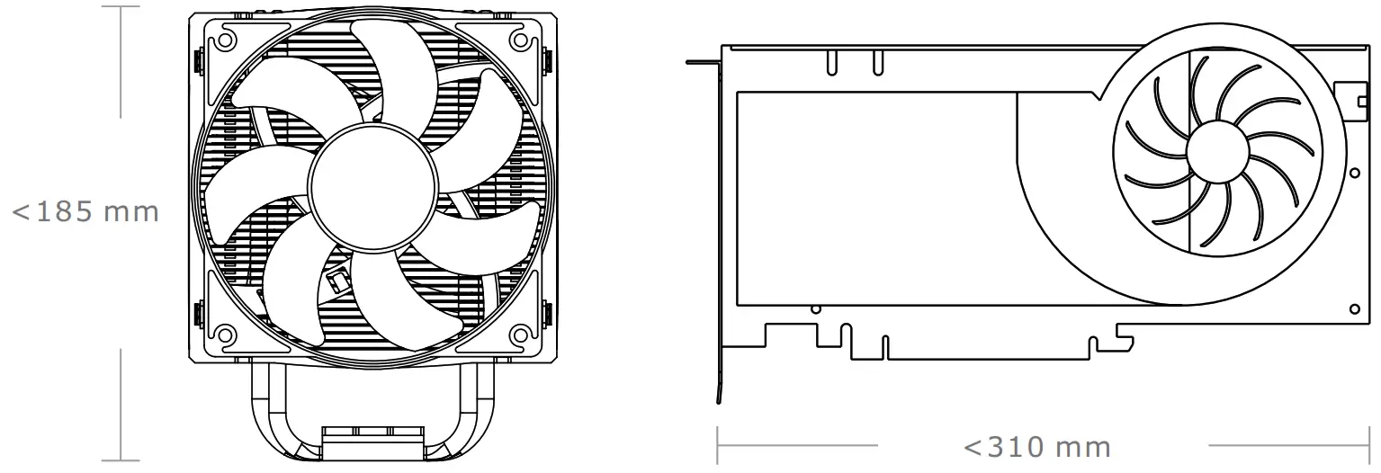
| Clearance | CPU cooler height limitation: 185 mm VGA length limitation: 310 mm (with HDD rack) 465 mm (without HDD rack) PSU length limitation: 220 mm (With Bottom Fan) |
Accessory
| Figure | Parts Name | Qty | Used for |
| Stand-off#6-32 x 6 mm | 4 | Motherboard | |
| Screw#6-32 x 6 mm | 4 | Power | |
| Screw#6-32 x 5 mm | 10 | HDD | |
| Screw M3 x 5 mm | 20 | Motherboard , ODD | |
| Screw M3 x 5 mm | 20 | 2.5″ HDD | |
| Nut Setter | 1 | Stand-off | |
| Screw Ø5 x 12mm | 4 | Case Fan | |
| Screw#6-32 x 32 mm | 4 | 200 mm x 30 mm Fan | |
| Cable Tie | 5 | Cable Management | |
| Buzzer | 1 | Motherboard Alarm |
Warning and Notice
Warning!!
CPU Cooler Height Limitation:
Please ensure that your CPU cooler does NOT exceed 185 mm (7.3 inches) height.
VGA (Add-on card) Length Limitation:
Please ensure that your VGA (Add-on card) does NOT exceed 310 mm (12.2 inches) length.
Installation Guide
Side Panels Disassembly
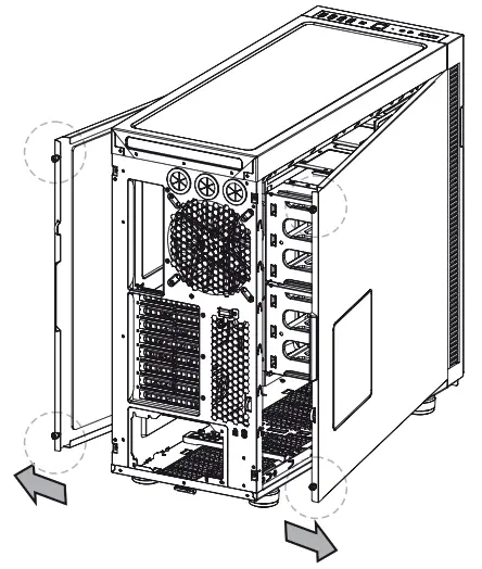
Remove the screws on the back of the chassis, and open the side panel
Power Supply Unit (PSU) Installation
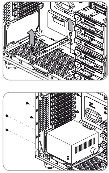
- Place the PSU in proper location.
- Adjust the PSU supporting bridge to the proper location and secure the PSU with screws.
Motherboard Installation
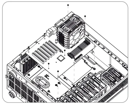
- Lay down the chassis.
- Install the motherboard in proper location and secure it with screws.
5.25″ Device Installation
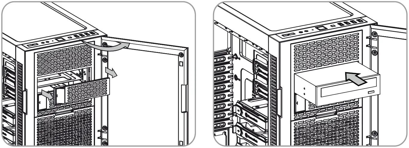
- Remove the 5.25” drive bay cover.
- Slide the 5.25” device into the drive bay to lock the device.
Note: Press the 5.25” tool-free mechanism to unlock the device.
3.5″ & 2.5″ HDD Installation
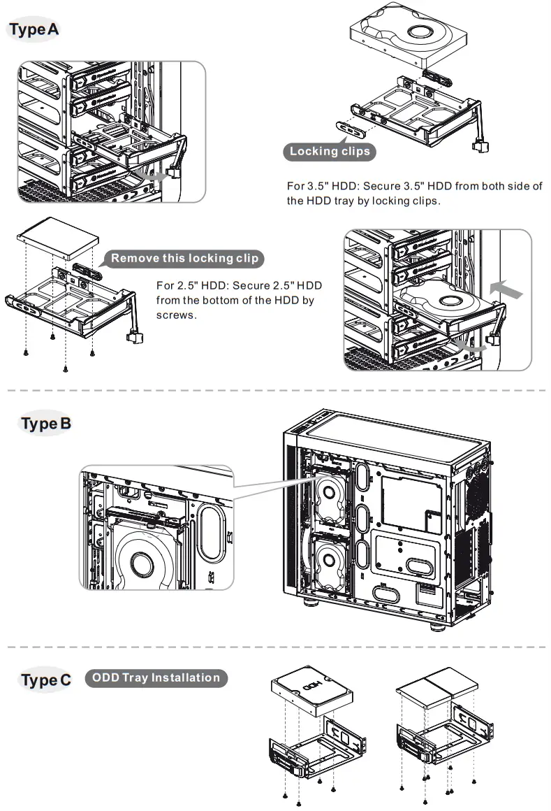
- Press a latch to pull the tray out.
- Remove the locking clips then position the HDD in the tray and secure the HDD with the locking clips.
- Slide the tray back to the drive bay.
PCI Card Installation
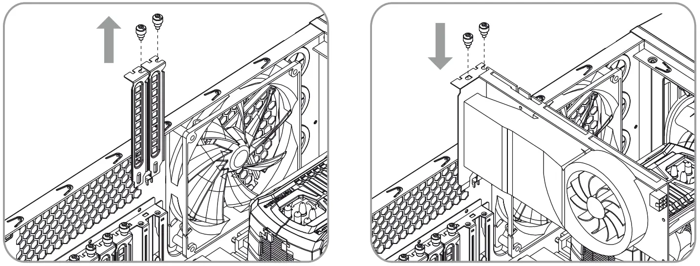
Insert the PCI card into the PCI slot, and secure it with screw.
Keyboard & Mouse Security Lock Usage
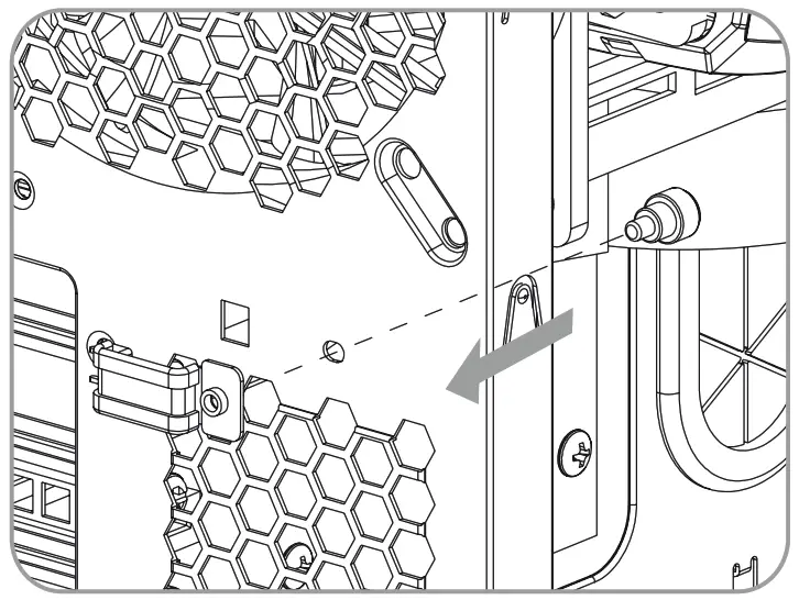
Place the keyboard or mouse cables through the “Keyboard & Mouse Security Lock” then secure it back to the back panel from inside of the chassis with screw.
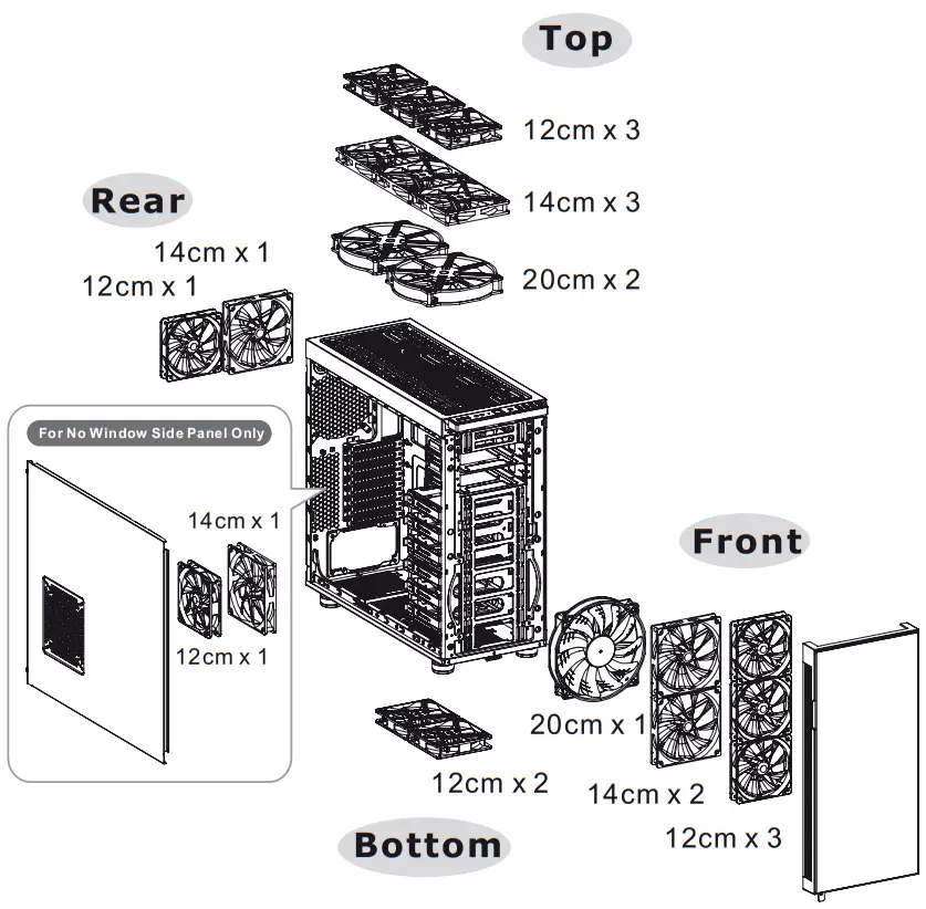
Air Cooling Installation
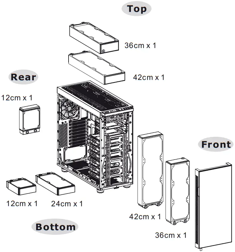
Liquid Cooling Installation
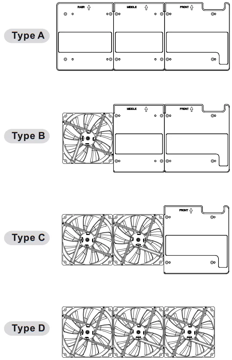
Filter Installation

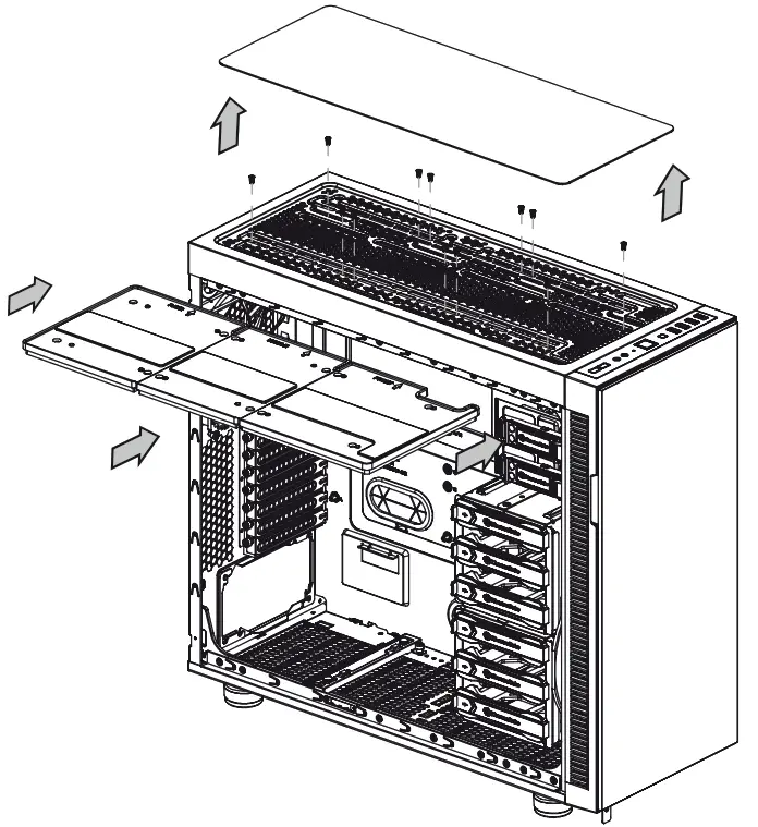
Soundproofed cover installation
Top panel
Remove soundproofed cover for additional fan slots
Side panel
For No Window Side Panel Only
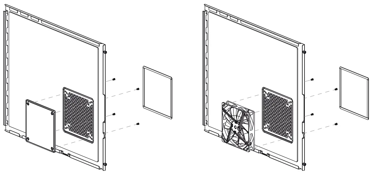
Flexible covers mounting, for balance air flow and sound absorbing
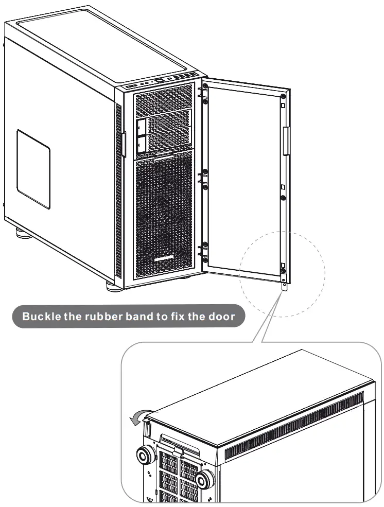
Door Lock Usage
Leads Installation
Leads Installation Guide
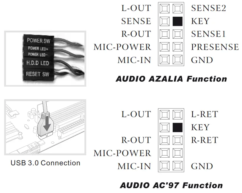
Case LED Connection/ On the front of the case, you can find some LEDs and switch leads. Please consult your user manual of your motherboard manufacturer, then connect these leads to the panel header on the motherboard.
USB 2.0 Connection/ Please consult your motherboard manual to find out the section of “USB connection”.
USB 3.0 connection/
- Make sure your motherboard supports USB 3.0 connection.
- Connect the USB 3.0 cable to the available USB 3.0 port on your computer.
Audio Connection/ Please refer to the following illustration of Audio connector and your motherboard user manual.
Please select the motherboard which used AC’97 or HD Audio(Azalia),(be aware of that your audio supports AC’97 or HD Audio (Azalia)) or it will damage your device(s).
![]() www.thermaltake.com
www.thermaltake.com
© 2015 Thermaltake Technology Co., Ltd. All Rights Reserved. 2015.05
All other registered trademarks belong to their respective companies.![]()


