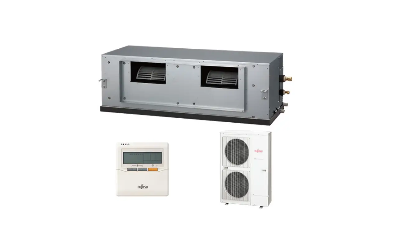
FUJITSU ARYC45LCTU Split Type Air Conditioner Duct Type
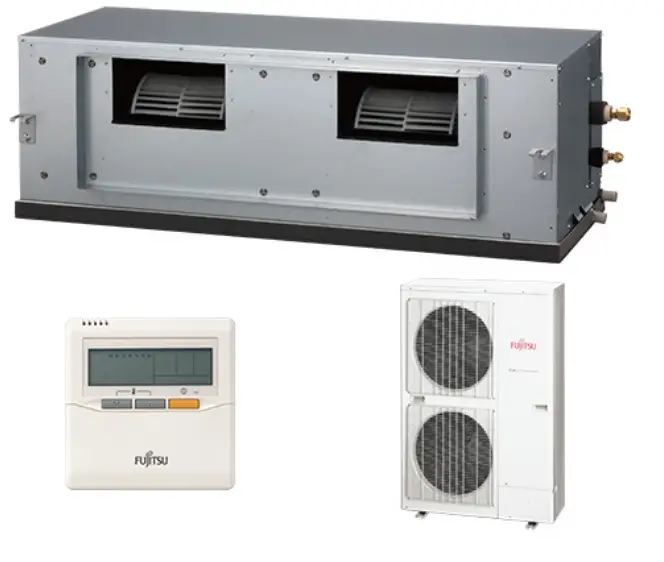
Split Type Air Conditioner Duct Type (50Hz)
The Split Type Air Conditioner Duct Type (50Hz) comes with an indoor unit and an outdoor unit. The product specifications, dimensions, refrigerant system diagram, circuit diagram, indoor PCB circuit diagram, outdoor PCB circuit diagram, error detection, parts (indoor unit), parts (outdoor unit), and accessories are included in the manual.
Specifications
| Type | Indoor Unit | Outdoor Unit |
|---|---|---|
| Cooling Capacity | 12.5 kW (ARYC45LCTU), 14.0 kW (ARYC54LCTU) | 14.0 kW (AOYD45LATT), 16.0 kW (AOYD54LATT) |
| Heating Capacity | 14.0 kW (ARYC45LCTU), 16.0 kW (ARYC54LCTU) | 14.0 kW (AOYD45LATT), 16.0 kW (AOYD54LATT) |
| Power Source | 400 V 50 Hz 3 4 W | 400 V 50 Hz 3 4 W |
| Running Current | Cooling: 6.1 A (ARYC45LCTU), 6.9 A (ARYC54LCTU) Heating: 5.5 A (ARYC45LCTU), 6.5 A (ARYC54LCTU) | Cooling: 4.65 kW (AOYD45LATT), 4.37 kW (AOYD54LATT) Heating: 3.67 kW (AOYD45LATT), 4.37 kW (AOYD54LATT) |
| Input Watts | Cooling: 4.06 kW (ARYC45LCTU), 3.81 kW (ARYC54LCTU) Heating: 3.08 kW (ARYC45LCTU), 3.66 kW (ARYC54LCTU) | Cooling: 3,450 g (AOYD45LATT), 4,200 g (AOYD54LATT) Heating: 3,450 g (AOYD45LATT), 4,950 g (AOYD54LATT) |
| E.E.R. | Cooling: 3.08 kW/kW (ARYC45LCTU), 3.01 kW/kW (ARYC54LCTU) Heating: 3.81 kW/kW (ARYC45LCTU), 3.66 kW/kW (ARYC54LCTU) | |
| Starting Current | Cooling & Heating: 10.0 A (ARYC45LCTU), 10.0 A (ARYC54LCTU) | Cooling & Heating: 11.0 A (AOYD45LATT), 12.0 A (AOYD54LATT) |
| Moisture Removal | 1.5 L/hr (ARYC45LCTU), 2.5 L/hr (ARYC54LCTU) | |
| Aircirculation Indoor | Cooling: 3,350 m3/h (ARYC45LCTU), 3,350 m3/h (ARYC54LCTU) Heating: 6,900 m3/h (ARYC45LCTU), 6,900 m3/h (ARYC54LCTU) | |
| Aircirculation Cooling | Cooling: 6,200 m3/h (AOYD45LATT), 6,900 m3/h (AOYD54LATT) | |
| Air circulation Heating | Heating: 6,900 m3/h (AOYD45LATT), 6,900 m3/h (AOYD54LATT) | |
| Maximum Current | Cooling & Heating: 11.0 A (AOYD45LATT), 12.0 A (AOYD54LATT) |
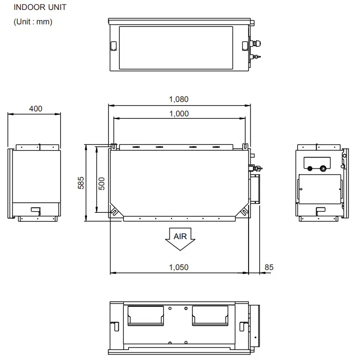
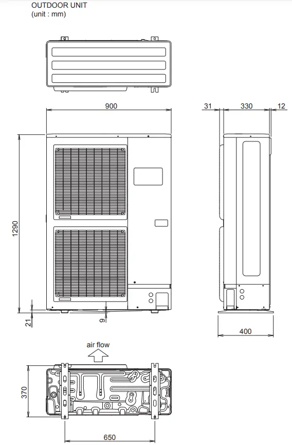
Dimensions
The indoor unit has a height of 400 mm, a width of 1,050 mm, and a depth of 500 mm. The outdoor unit has a height of 1,290 mm, a width of 900 mm, and a depth of 330 mm.
Refrigerant System Diagram
The refrigerant system diagram shows the components of the indoor and outdoor units, including the compressor, heat exchanger, pressure sensor, and thermistors.
Product Usage Instructions
- Ensure that the product is properly installed according to the installation instructions provided in the manual.
- Connect the product to a power source with a voltage of 400 V and frequency of 50 Hz.
- Turn on the product and select the desired mode (cooling or heating) using the remote control.
- Adjust the temperature setting using the remote control.
- To prevent malfunction, follow the recommended maximum pipe length and maximum pipe height for the product.
- Clean the air filters regularly to ensure optimal performance.
- If an error occurs, refer to the error detection section in the manual for troubleshooting steps.
SPECIFICATIONS
ELECTRICAL DATA
| TYPE | Cooling & Heating | ||
| INDOOR UNIT | ARYC45LCTU | ARYC54LCTU | |
| OUTDOOR UNIT | AOYD45LATT | AOYD54LATT | |
| COOLING CAPACITY | 12.5 kW | 14.0 kW | |
| HEATING CAPACITY | 14.0 kW | 16.0 kW | |
| POWER SOURCE | 400 V 50 Hz 3 4 W | ||
| RUNNING CURRENT | Cooling | 6.1 A | 6.9 A |
| Heating | 5.5 A | 6.5 A | |
| INPUT WATTS | Cooling | 4.06 kW | 4.65 kW |
| Heating | 3.67 kW | 4.37 kW | |
| E.E.R. | Cooling | 3.08 kW/kW | 3.01 kW/kW |
| Heating | 3.81 kW/kW | 3.66 kW/kW | |
| STARTING CURRENT | 10.0 A | 10.0 A | |
| MOISTURE REMOVAL | 1.5 L/hr | 2.5 L/hr | |
| AIRCIRCULATION INDOOR | 3,350 m3/h | 3,350 m3/h | |
| AIRCIRCULATION OUTDOOR | Cooling | 6,900 m3/h | 6,900 m3/h |
| Heating | 6,200 m3/h | 6,900 m3/h | |
| MAXIMUM CURRENT | 11.0 A | 12.0 A | |
FAN MOTOR
|
INDOOR UNIT | Discrimination | MFA-60TTFS | |
| High speed | 1,300 r.p.m. | 1,300 r.p.m. | |
| Middle speed | 1,150 r.p.m. | 1,150 r.p.m. | |
| Low speed | 1,000 r.p.m. | 1,000r.p.m. | |
| OUTDOOR UNIT (cool / heat) | Discrimination | MFE-54TV | |
| Upper fan | 900 / 780 r.p.m. | 900 / 850 r.p.m. | |
| Lower fan | 800 / 750 r.p.m. | 800 / 850 r.p.m. | |
NOISE LEVEL
| INDOOR UNIT | High speed | 47 dB | 47 dB |
| Middle speed | 43 dB | 43 dB | |
| Low speed | 40 dB | 40 dB | |
| OUTDOOR UNIT | Cooling | 54 dB | 55 dB |
| Heating | 54 dB | 56 dB |
Note : Static pressure : 100pa Duct length : Inlet 1m, Outlet 2m
DIMENSIONS
| INDOOR UNIT H x W x D | 400 x 1,050 x 500 mm |
| OUTDOOR UNIT H x W x D | 1,290 x 900 x 330 mm |
WEIGHT
| INDOOR UNIT Gross / Net | 51 kg / 46 kg |
| OUTDOOR UNIT Gross / Net | 117 kg / 107 kg |
COMPRESSOR AND REFRIGERANT
| TYPE | Hermetic type, Inverter, 4 poles, 3 phase, DC motor, Twin Rotary | |
| DISCRIMINATION | 808 677 80 | |
| WEIGHT (with oil) | 25.6 kg | |
| REFRIGERANT TYPE | R410A | |
| PRECHARGED REFRIGERANT | 3,450 g | |
| MAX PIPE LENGTH | 75 m | |
| MAX PIPE HEIGHT | 30 m | |
| Pipe length FULL CHARGE | 30 m | 3,450 g |
| 45 m | 4,200 g | |
| 60 m | 4,950 g | |
| 75 m | 5,700 g | |
| ADDITIONAL CHARGE | 50 g/m | |
OUTLINE AND DIMENSIONS
REFRIGERANT SYSTEM DIAGRAM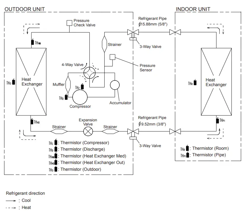
CIRCUIT DIAGRAM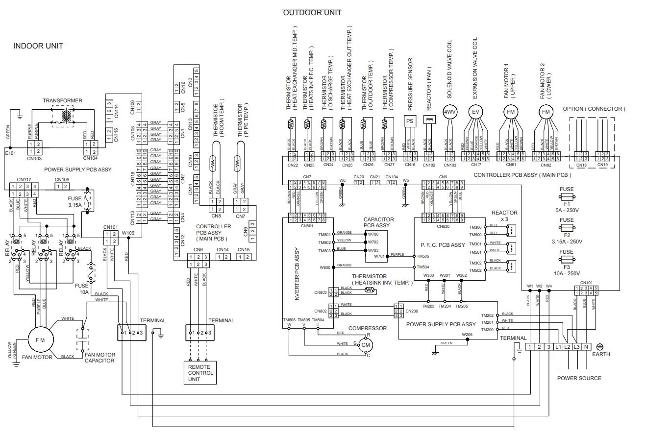
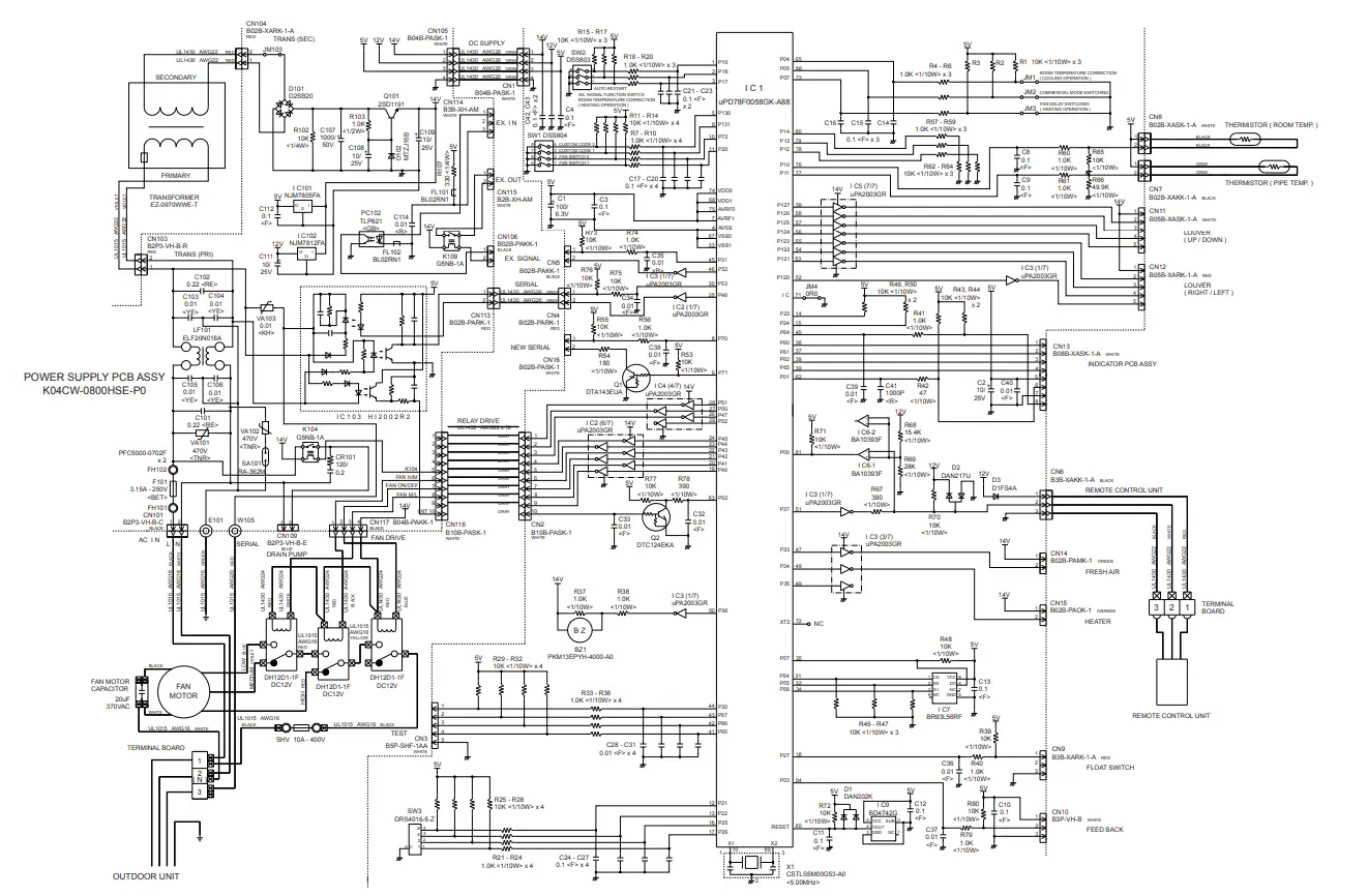
INDOOR PCB CIRCUIT DIAGRAM
INDOOR PCB CIRCUIT DIAGRAMINDOOR PCB CIRCUIT DIAGRAM
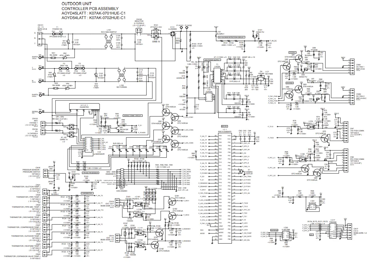
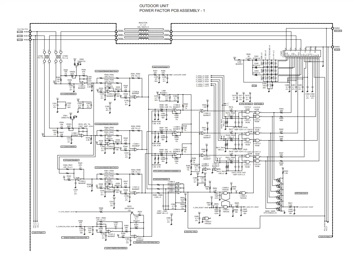
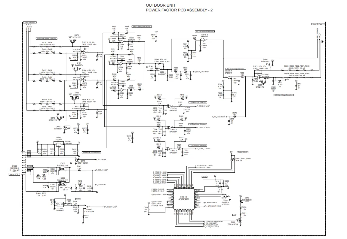
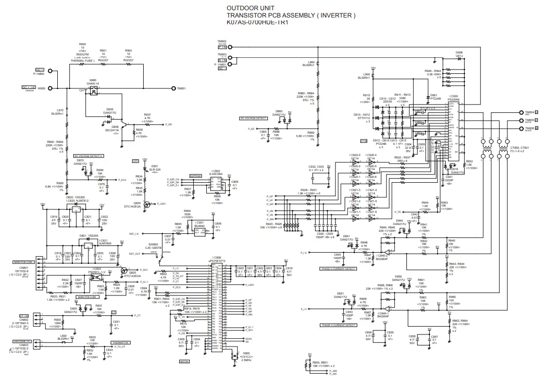
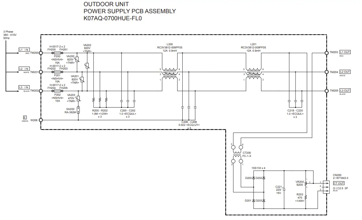
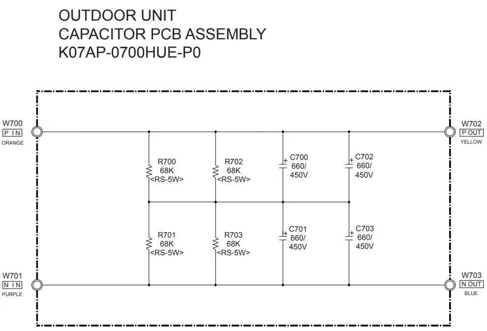
OUTDOOR PCB CIRCUIT DIAGRAM
INVERTER ASSEMBLY AOYD45LATT : EZ-0071HUE AOYD54LATT : EZ-0072HUE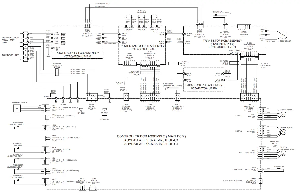
ERROR DETECTION
- REMOTE CONTROL Troubleshooting at the remote control LCD This is possible only on the wired remote control.
- Self-diagnosis If an error occurs, the following display will be shown.(“EE” will appear in the set room temperature display.)
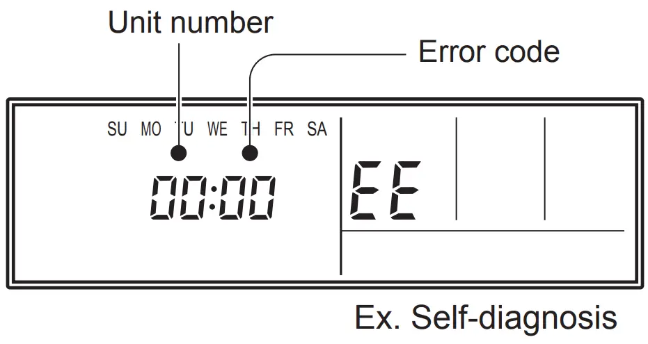
- If “CO” appears in the unit number display, there is a remote control error. Refer to the installation instruction sheet included with the remote control.
| Error code | Error contents |
| 01 13 26 27 | Indoor signal error |
| 00 | Wired remote controller abnormal |
| 02 | Indoor room temperature sensor error |
| 04 | Indoor heat exchanger temperature sensor (middle) error |
| 28 | Indoor heat exchanger temperature sensor (inlet) error |
| 09 | Float switch operated |
| 0c | Outdoor discharge pipe temperature sensor error |
| 06 | Outdoor heat exchanger temperature sensor (outlet) error |
| 0A | Outdoor temperature sensor error |
| 0E | Heat sink thermistor (Inverter) error |
| 15 | Compressor temperature sensor error |
| 1d | 2-way valve temperature sensor error |
| 1E | 3-way valve temperature sensor error |
| 29 | Outdoor heat exchanger temperature sensor (middle) error |
| 2d | Heat sink thermistor (P.F.C.) error |
| 20 | Indoor manual auto switch abnormal |
| 2A | Power supply frequency detection error |
| 17 | IPM protection |
| 18 | CT error |
| 1A | Compressor location error |
| 1b | Outdoor fan error |
| 1F | Connected indoor unit abnormal |
| 1c | Outdoor unit computer communication error |
| 2E | Inverter error |
| 12 | Indoor fan abnormal |
| 0F | Discharge temperature error |
| 24 | Excessive high pressure protection on cooling |
| 2c | 4-way valve abnormal |
| 16 | Pressure switch abnormal, Pressure sensor abnormal |
| 2b | Compressor temperature error |
| 2F | Low pressure error |
| 19 | Active filter abnormal |
| 25 | P.F.C. circuit error |
| 30 | Refrigerant circuit address set-up error |
| 31 | Master unit, Slave unit set-up error |
| 32 | Connected the indoor number set-up error |
| 33 | P.F.C. PCB error |
OUTDOOR UNIT TEST RUN
CAUTION: Always turn on the power 6 hours prior to the start of the operation in order to protect the compressor. Check items before performing the test run Make sure to perform the test run. Before performing the test run, be sure to check the following points.
- Is gas leaking? Check connection of each pipe (flare connection part, brazing part).
- Is a breaker installed to the power cable of the outdoor unit ?
- Has each cable been securely connected to the terminal according to the specifications ?
- Are the 3-way valves (gas pipes and liquid pipes) of the outdoor units open?
- Has the power been supplied to the unit for at least 6 hours ?
- Has the necessary local setting been done ?
- Check insulation resistance of 1 M or more using a 500V mega tester. If no problems are found with the above items, perform the test run according to “Test run method”. If any problems are found, immediately resolve the problem and re-check the items.
Test run method
CAUTION: If the test run is performed for 1 outdoor unit in a group control system installation, the test run will also be performed for the other units. Therefore, make sure that all of the units have been installed before starting a test run. (Group control system installation described in “SPECIAL INSTALLATION METHODS” in the installation manual of the indoor unit.) Operate [ENTER] (TEST RUN) switch on the display board by the following procedure.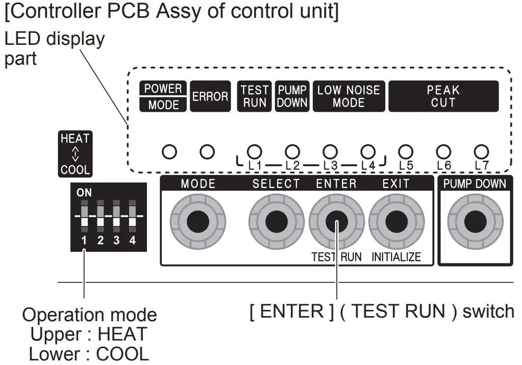
Operating procedures for the test run
- Check the 3-way valves (both at the liquid side and gas side) are opened.
- Set the operation mode to “COOL” or “HEAT”.
POWER ERROR
TEST RUN (L1)
PUMP DOWN (L2)
LOW NOISE (L3) (L4) PEAK CUT (L5) (L6) (L7)
MODE 

Sign
 lights on.
In the first test run, be sure to set the operation mode to “COOL”. The operation mode cannot be switched between “COOL” and “HEAT” during the test run. To switch the operation mode between “COOL” and “HEAT”, stop the test run, switch the operation mode, and then start the test run again. - Press [ENTER] (TEST RUN) switch for more than 3 seconds.
POWER ERROR
TEST RUN (L1)
PUMP DOWN (L2)
LOW NOISE (L3) (L4) PEAK CUT (L5) (L6) (L7)
MODE “TEST RUN” LED will light on.
If the compressor is operating at starting the test run, the compressor will stop and, after a while, the test run will start. Either of the above “LOW NOISE” or “PEAK CUT” will light on during the test run if local setting function is selected. - Confirm operating status.
- Press [ENTER] (TEST RUN) switch again.
POWER ERROR
TEST RUN (L1)
PUMP DOWN (L2)
LOW NOISE (L3) (L4) PEAK CUT (L5) (L6) (L7)
MODE “TEST RUN” LED lights off, and TEST RUN stops.
Test run will finish after about 60 minutes automatically. At the same time, “TEST RUN” LED will light off. Test run may be stopped before operating for 60 minutes if an error occurs after a starting test run.
OUTDOOR UNIT ERROR CODE DISPLAY
When an error occurs, “short-press” the [ENTER] switch once. The number of blinks of the LED indicates the type of error. How to check error code?
- Display when an error occurs
POWER ERROR
TEST RUN (L1) PUMP DOWN (L2) LOW NOISE (L3) (L4) PEAK CUT (L5) (L6) (L7)
MODE Blinks (Hi-speed)
- Check that the “ERROR” LED blinks, and then “short- press” the [ENTER] switch once.
- Display while an error code is blinking
POWER ERROR
TEST RUN (L1) PUMP DOWN (L2) LOW NOISE (L3) (L4) PEAK CUT (L5) (L6) (L7)
MODE Blinks (Twice) Blinks - The “POWER MODE” LED will blink twice and the “ERROR” LED will blink several times. The number of blinks of the “ERROR” LED varies according to the type of error. For details, refer to the right table.
Error code check table
| Number of blinks (LED) | Error type |
| 1 | Serial forward transfer error |
| 2 | Discharge thermistor error |
| 3 | Heat-exchange thermistor (outlet) error |
| 4 | External temperature thermistor error |
| 5 | Heat-exchange thermistor (intermediate) error |
| 6 | Discharge temperature protection (permanent stoppage) |
| 7 | Compressor thermistor error |
| 8 | Heatsink thermistor (inverter) error |
| 9 | Pressure switch (sensor) error |
| 10 | Compressor temperature protection (permanent stoppage) |
| 11 | Connection with indoor unit error |
| 12 | Current trip (permanent stoppage) |
| 13 | Detection of compressor position error (permanent stoppage) |
| 14 | Compressor start up error (permanent stoppage) |
| 15 | Fan motor (1) error (permanent stoppage) |
| 16 | Fan motor (2) error (permanent stoppage) |
| 17 | Heatsink thermistor (P.F.C.) error |
| 18 | Inverter error |
| 19 | P.F.C. error |
| 20 | Low pressure abnormal |
| 21 | Indoor unit abnormality condition |
SPECIAL INSTALLATION SETTING
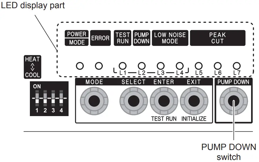
OUTDOOR UNIT PUMP DOWN (Refrigerant collecting operation) Perform the following procedures to collect the refrigerant when moving the indoor unit or outdoor unit
WARNING:Never touch electrical components such as the terminal blocks or reactor except the switch on the display board. It may cause a serious accident such as electric shock.
CAUTION
- Perform the pump down operation before disconnecting any refrigerant pipe or electric cable.
- Collect refrigerant from the service port or the 3-way valve if pump down cannot be performed.
- In case of a group control system installation, do not turn the power off pump down is completed in all outdoor units.
- (Group control system installation described in “SPECIAL INSTALLATION METHODS” in the installation manual of the indoor unit.)
- Operate [PUMP DOWN] switch on the display board in the manner described below.


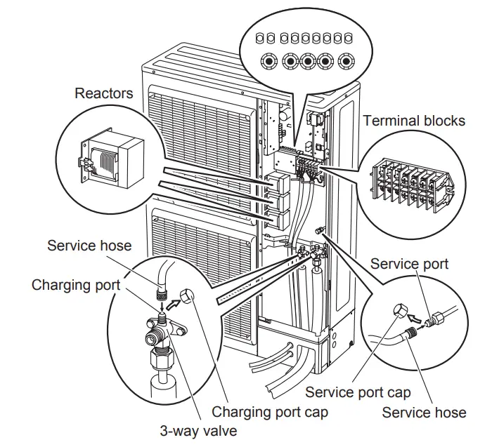
Preparation for pump down
Confirm that the power is off, and then open the service panel.
Pump down procedure
- Check the 3-way valves (both at the liquid side and gas side) are opened.
- Turn the power on.
POWER ERROR
TEST RUN (L1)
PUMP DOWN (L2)
LOW NOISE (L3) (L4) PEAK CUT (L5) (L6) (L7)
MODE - Press [PUMP DOWN] switch for 3 seconds or more after 3 minutes after power on.
POWER ERROR
TEST RUN (L1) PUMP DOWN (L2) LOW NOISE (L3) (L4) PEAK CUT (L5) (L6) (L7)
MODE LED display lights on as shown in the above figure, and the fans and the compressor start operating. If the [PUMP DOWN] switch is pressed while the compressor is operating, the compressor will stop, then start again in about 3 minutes.
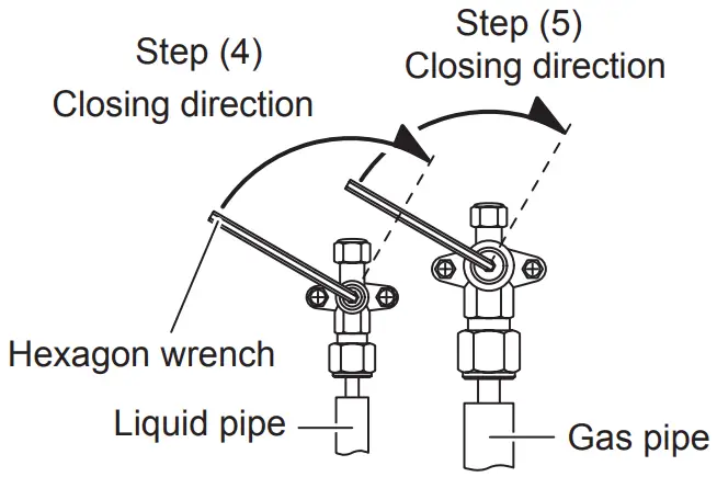
- LED display will change as shown below about 3 minutes after the compressor starts. Fully close the 3- way valve on the liquid pipe side at this stage.
POWER ERROR
TEST RUN (L1) PUMP DOWN (L2) LOW NOISE (L3) (L4) PEAK CUT (L5) (L6) (L7)
MODE If the valve on the liquid pipe side is not closed, the pump down cannot be performed.
- When LED display changes as shown in the below figure, close the 3-way valve on the gas pipe side tightly.
POWER ERROR
TEST RUN (L1) PUMP DOWN (L2) LOW NOISE (L3) (L4) PEAK CUT (L5) (L6) (L7)
MODE If the valve on the gas pipe side is not closed, refrigerant may flow into the piping after the compressor stops

- LED display changes after 1 minute as shown in the figure below
POWER ERROR
TEST RUN (L1)
PUMP DOWN (L2)
LOW NOISE (L3) (L4) PEAK CUT (L5) (L6) (L7)
MODE Fans and compressor stop automatically. If the pump down is successfully completed (the above LED display is shown), the outdoor unit remains stopped until the power is turned off.
- Turn the power off.
POWER ERROR
TEST RUN (L1)
PUMP DOWN (L2)
LOW NOISE (L3) (L4) PEAK CUT (L5) (L6) (L7)
MODE PUMP DOWN is completed. Note: To stop pump down, press the [PUMP DOWN] switch again. To start the pump down again after the compressor is automatically stopped due to an error, turn the power off and open the 3-way valves. Wait 3 minutes, turn the power on and start the pump down again. When starting the operation after completion of the pump down, turn the power off, and then open the 3-way valves. Wait 3 minutes, turn the power on and perform a test run in the “COOL” operation mode.


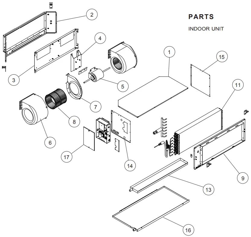
| Ref. | Description | Parts number | |
| 1 | Plate Top Sub Assy | 9372576014 | |
| 2 | Kit (Panel Front Sub Assy) | 9372637029 | |
| 3 | Panel Fan Assy | 9372035009 | |
| 4 | Bracket Motor Assy | 9372037003 | |
| 5 | Motor, Induct | 9602802012 | |
| 6 | Casing A | 9372057018 | |
| 7 | Casing B | 9372058015 | |
| 8 | Sirocco Fan | 9372059012 | |
| 9 | Kit (Panel Rear Sub Assy) | 9372636022 | |
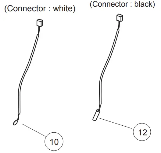
| 10 | Room Thermistor | 9703299216 | |
| 11 | Evaporator Assy | 9373875017 | |
| 12 | Pipe Thermistor | 9703297113 | |
| 13 | Drain Pan Assy | 9372579015 | |
| 14 | Kit (Panel Right Sub Assy) | 9372916025 | |
| 15 | Kit (Panel Left Sub Assy) | 9372581018 | |
| 16 | Drain Pan Sub Assy | 9372582015 | |
| 17 | Cover Box | 9372061008 |
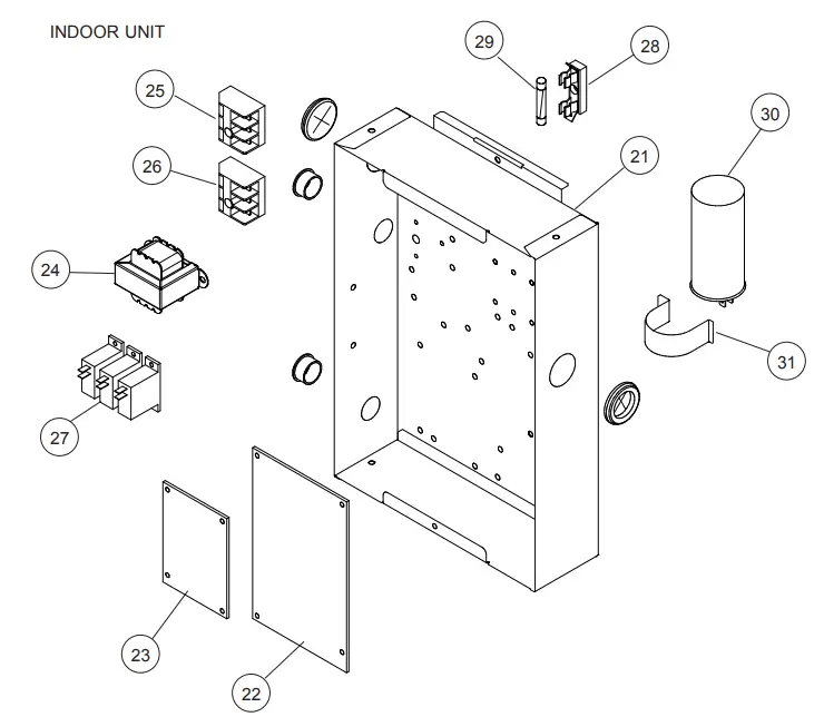
| Ref. | Description | Parts number | |
| 21 | Control Box Assy | 9374854028 | |
| 22 | Power Supply PCB Assy | 9705668102 | |
| 23 | Controller PCB Assy (45) | 9705246232 | |
| (K03BZ-0802HSE-C1) | |||
| 23 | Controller PCB Assy (54) | 9705246225 | |
| (K03BZ-0801HSE-C1) | |||
| 24 | Transformer (Power) | 9704129017 | |
| 25 | Terminal 3P | 9703345012 | |
| 26 | Terminal 3P | 9306489045 | |
| 27 | Relay | 9900294014 | |
| 28 | Fuse Holder | 0501454012 | |
| 29 | Fuse | 0600384029 | |
| 30 | Capacitor, Plastic | 9900269111 | |
| 31 | Capacitor Clamp | 9308114006 | |
| — | Thermo. Spring A | 313728262708 | |
| — | Remote Control | 9372266199 |
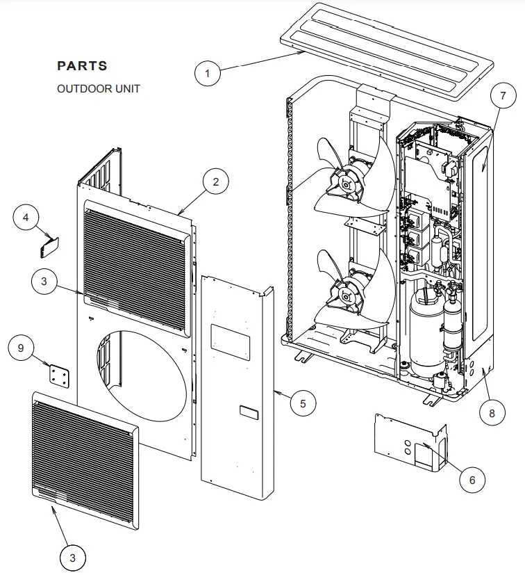
| Ref. | Description | Parts number |
| 1 | Top Panel Sub Assy | 9374417032 |
| 2 | Front Panel | 9374094028 |
| 3 | Fan Guard | 9374330010 |
| 4 | Grip Side | 9374173013 |
| 5 | Sevice Panel Sub Assy | 9374415076 |
| 6 | Pipe Cover Front | 9378861015 |
| 7 | Right Panel Sub Assy | 9374416158 |
| 8 | Pipe Cover Rear | 9378862012 |
| 9 | Fan Guard Cover | 9378111011 |
| — | Emblem Rear | 9351355005 |
| — | Protective Net | 9375381042 |
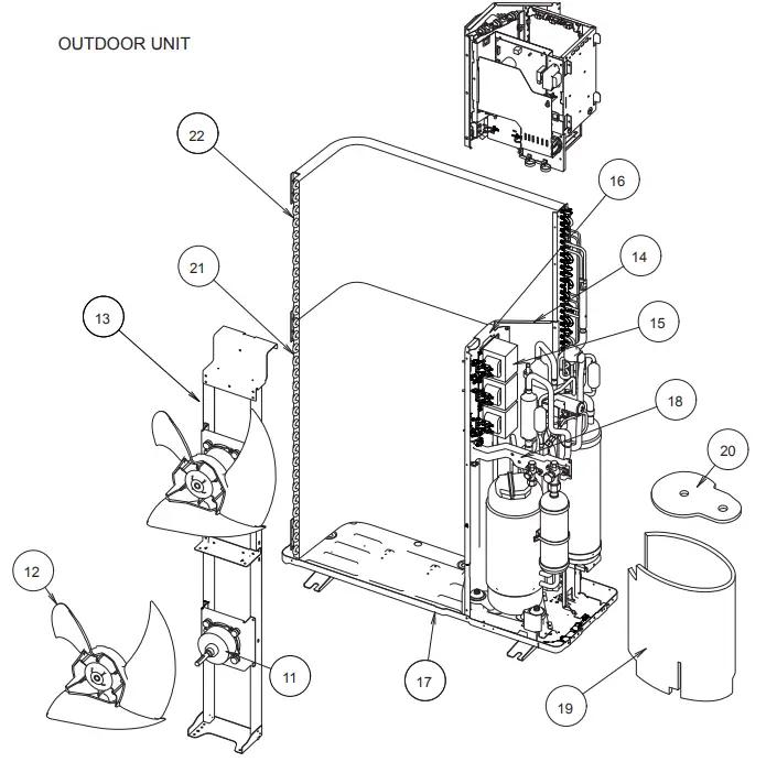
| Ref. | Description | Parts number |
| 11 | Motor DC Brushless | 9602749010 |
| 12 | Propeller Fan Assy | 9366378020 |
| 13 | Motor Bracket Sub Assy | 9374418145 |
| 14 | Separate Wall Sub Assy | 9374413195 |
| 15 | Reactor Assy | 9900246013 |
| 16 | Reactor Holder Sub Assy | 9379067003 |
| 17 | Base Assy | 9374166220 |
| 18 | Valve Plate | 9378804012 |
| 19 | Compressor Cover A | 9378611023 |
| 20 | Compressor Cover B | 9378612020 |
| 21 | Condenser A Assy | 9374433018 |
| 22 | Condenser B Assy | 9374434015 |
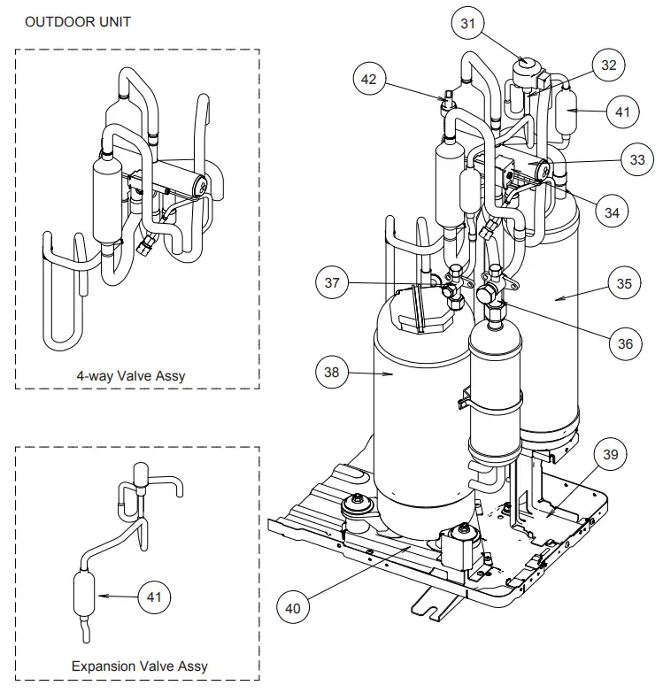
| Ref. | Description | Parts number |
| 31 | Coil (Expansion Valve) | 9900190057 |
| 32 | Expansion Valve Assy | 9370947182 |
| 33 | 4-way Valve Assy | 9374425167 |
| 34 | Solenoid | 9970055041 |
| 35 | Accumulator | 9379014014 |
| 36 | 3-way Valve Assy | 9379079006 |
| 37 | 3-way Valve Assy | 9379077002 |
| 38 | Compressor Assy | 9379013017 |
| 39 | Accumulator Holder | 9378800014 |
| 40 | Comp Plate Assy | 9378826014 |
| 41 | Strainer Assy | 9372524039 |
| 42 | Sensor | 9900505011 |
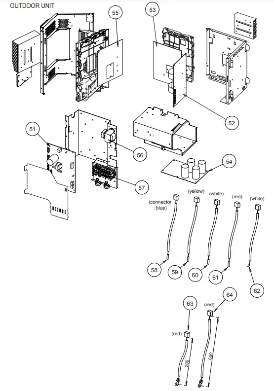
| Ref. | Description | Parts number |
| 51 | Main PCB Assy (45) | 9707627022 |
| 51 | Main PCB Assy (54) | 9707627039 |
| 52 | Filter PCB Assy | 9707609011 |
| 53 | PFC PCB Assy | 9707629019 |
| 54 | Capacitor PCB Assy | 9707608014 |
| 55 | Inverter PCB Assy | 9707628012 |
| 56 | Reactor Assy | 9900481018 |
| 57 | Terminal | 9900428082 |
| 58 | Compressor Thermistor | 9900516000 |
| 59 | Thermistor (Discharge) | 9900515003 |
| 60 | Thermistor (Heat Exchanger Med) | 9900513009 |
| 61 | Thermistor (Heat Exchanger Out) | 9900514006 |
| 62 | Thermistor (Outdoor) | 9900517007 |
| 63 | Heatsink Thermistor (Inverter) | 9900518011 |
| 64 | Heatsink Thermistor (PFC) | 9900518028 |
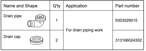
ACCESSORIES
INDOOR UNIT
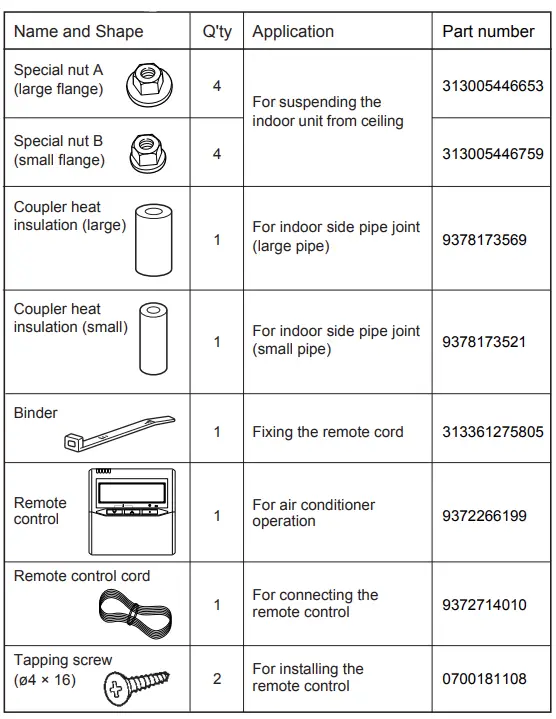
OUTDOOR UNIT