![]()
![]() SPLIT TYPE
SPLIT TYPE
AIR CONDITIONER
DUCT TYPE (50Hz)
Service manual
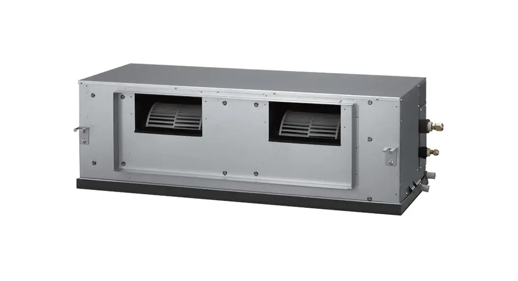
ARYG45LHTA Split Type Air Conditioner Duct Type
| Indoor unit | Outdoor unit |
| ARYG45LHTA | AOYG45LATT |
| ARYG54LHTA | AOYG54LATT |
SPECIFICATIONS
ELECTRICAL DATA
| TYPE | Cooling & Heating | ||
| INDOOR UNIT | ARYG45LHTA | ARYG54LHTA | |
| OUTDOOR UNIT | AOYG45LATT | AOYG54LATT | |
| COOLING CAPACITY | 12.5 kW | 14.0 kW | |
| HEATING CAPACITY | 14.0 kW | 16.0 kW | |
| POWER SOURCE | 400 V, 50 Hz, 3 phase, 4 W | ||
| RUNNING CURRENT | Cooling | 6.1 A | 6.9 A |
| Heating | 5.5 A | 6.5 A | |
| INPUT WATTS | Cooling | 4.06 kW | 4.65 kW |
| Heating | 3.67 kW | 4.37 kW | |
| E.E.R. Cooling | 3.08 kW/kW | 3.01 kW/kW | |
| C.O.P. Heating | 3.81 kW/kW | 3.66 kW/kW | |
| MOISTURE REMOVAL | 1.5 L/hr | 2.5 L/hr | |
| AIRCIRCULATION INDOOR | 3,350 m3/h | 3,350 m3/h | |
| AIRCIRCULATION OUTDOOR | Cooling | 6,750 m3/h | 6,900 m3/h |
| Heating | 6,200 m3/h | 6,900 m3/h | |
| MAXIMUM CURRENT | 11.0 A | 12.0 A | |
FAN MOTOR
| INDOOR UNIT, Discrimination | MFA-60TTFS | ||
| INDOOR UNIT | High | 1,300 r.p.m. | |
| Medium | 1,150 r.p.m. | ||
| Low | 1,000 r.p.m. | ||
| OUTDOOR UNIT, Discrimination | MFE-54VVT | ||
| OUTDOOR UNIT Cooling | Upper fan | 850 r.p.m. | 900 r.p.m. |
| Lower fan | 800 r.p.m. | 800 r.p.m. | |
| OUTDOOR UNIT Heating | Upper fan | 780 r.p.m. | 870 r.p.m. |
| Lower fan | 750 r.p.m. | 840 r.p.m. | |
NOISE LEVEL
| INDOOR UNIT | High | 47 dB | |
| Medium | 43 dB | ||
| Low | 40 dB | ||
| OUTDOOR UNIT | Cooling | 54 dB | 55 dB |
| Heating | 54 dB | 56 dB | |
COMPRESSOR AND REFRIGERANT
| TYPE | Hermetic type, Inverter, 4 poles, 3 phase, DC motor, Twin Rotary | |
| DISCRIMINATION | DA422A3F-29ZAD | |
| WEIGHT (with oil) | 23.0 kg | |
| REFRIGERANT TYPE | R410A | |
| PRECHARGED REFRIGERANT | 3,450 g | |
| MAX PIPE HEIGHT | 30 m | |
| Pipe length FULL CHARGE | 30 m | 3,450 g |
| 45 m | 4,200 g | |
| 60 m | 4,950 g | |
| 75 m | 5,700 g | |
| ADDITIONAL CHARGE | 50 g/m | |
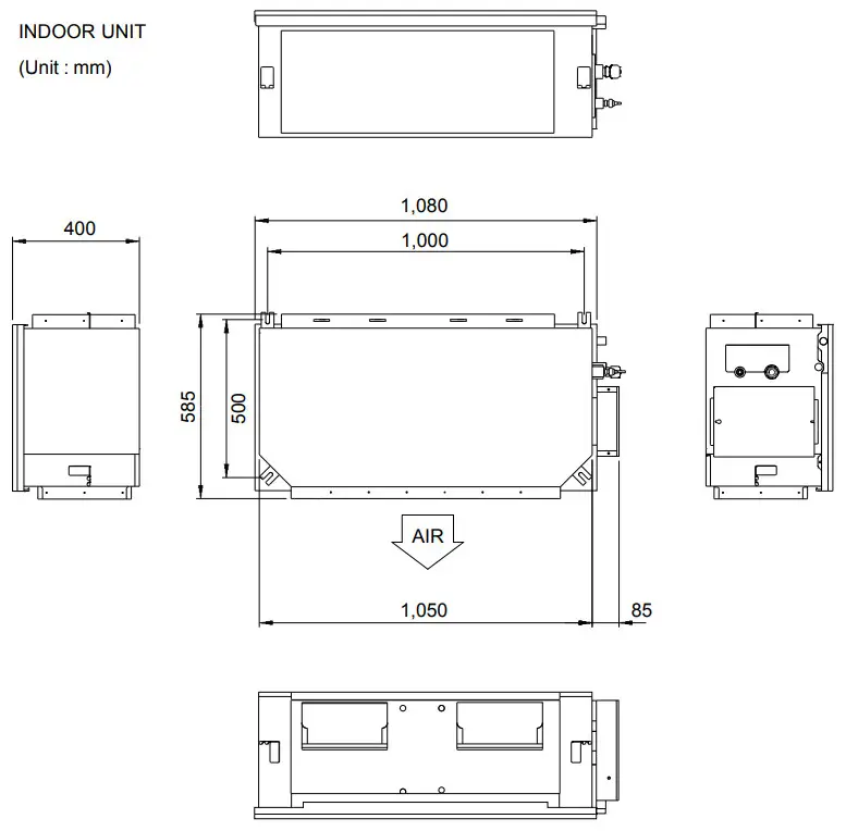
DIMENSIONS
| INDOOR UNIT H x W x D | 400 x 1,050 x 500 mm |
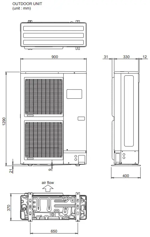
| OUTDOOR UNIT H x W x D | 1,290 x 900 x 330 mm |
WEIGHT
| INDOOR UNIT Shipping / Net | 51 kg / 46 kg |
| OUTDOOR UNIT Shipping / Net | 113 kg / 104 kg |
DIMENSIONS
OUTDOOR UNIT
(unit : mm)
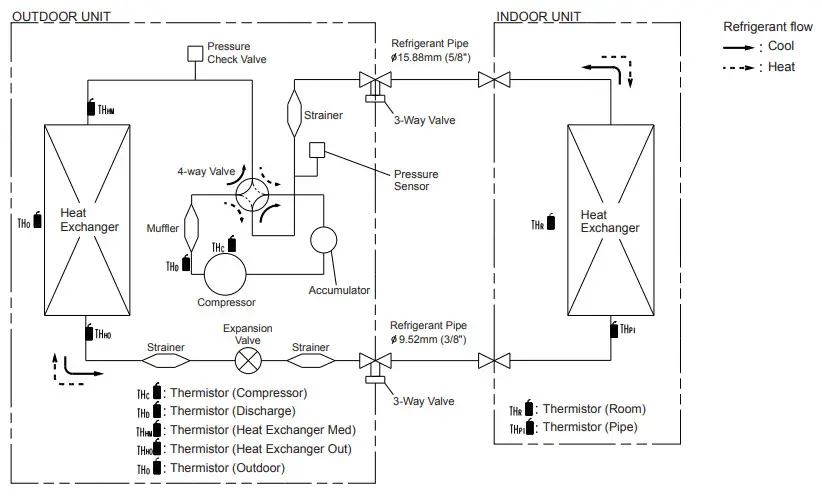
REFRIGERANT SYSTEM DIAGRAM
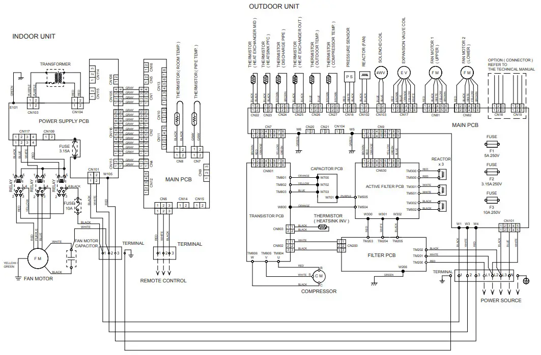
CIRCUIT DIAGRAM
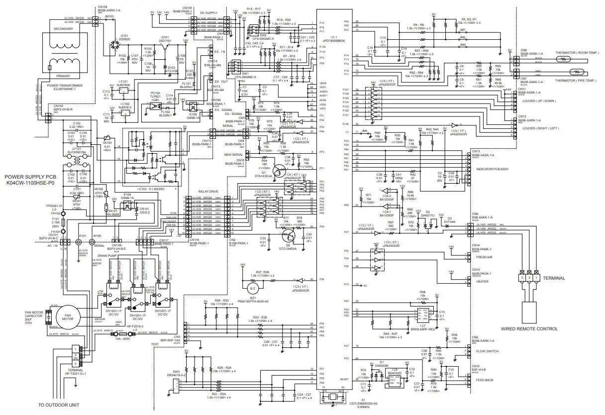
OUTDOOR PCB CIRCUIT DIAGRAM
INVERTER ASSEMBLY
AOYG45LATT : EZ-0111WHUE
AOYG54LATT : EZ-0111YHUE 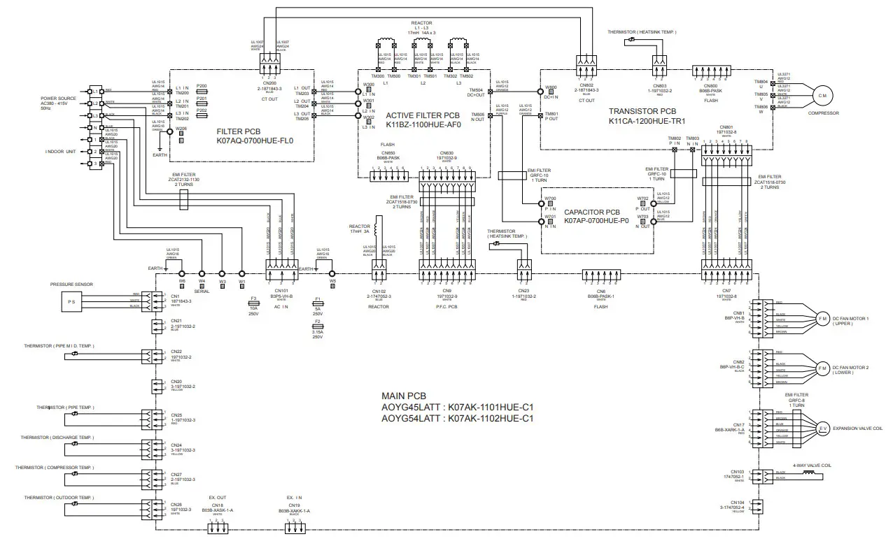
OUTDOOR UNIT
MAIN PCB
AOYG45LATT : K07AK-1101HUE-C1
AOYG54LATT : K07AK-1102HUE-C1 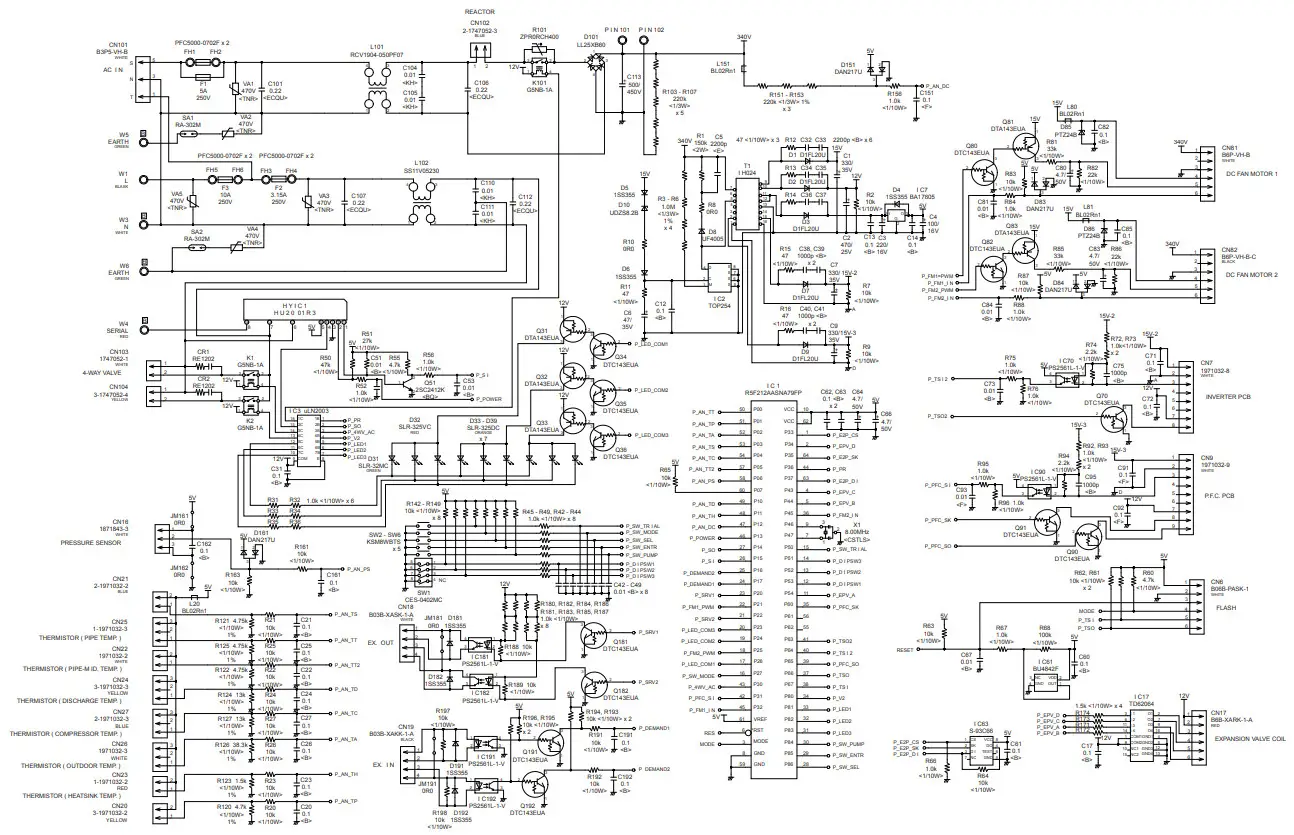 OUTDOOR UNIT
TRANSISTOR PCB
K11CA-1200HUE-TR1 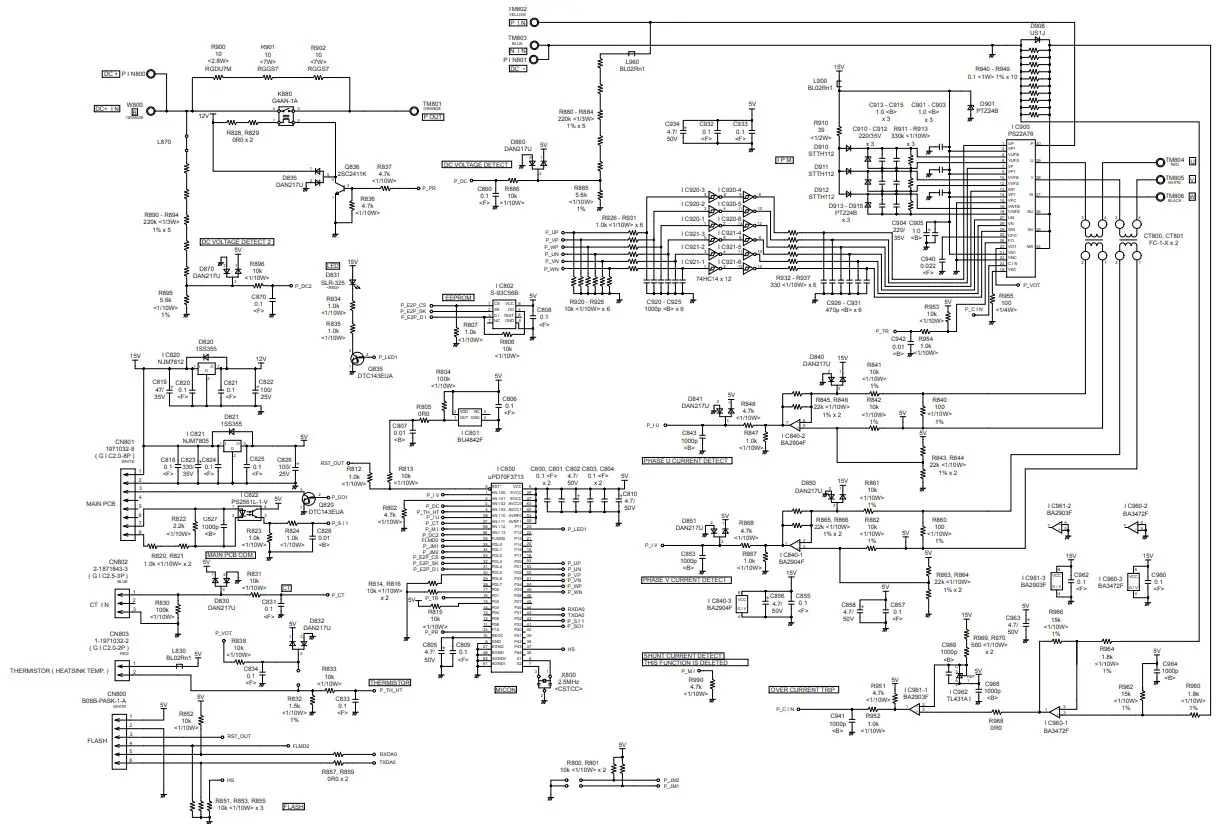
OUTDOOR UNIT
ACTIVE FILTER PCB – 1
K-11BZ-1100HUE-AF0 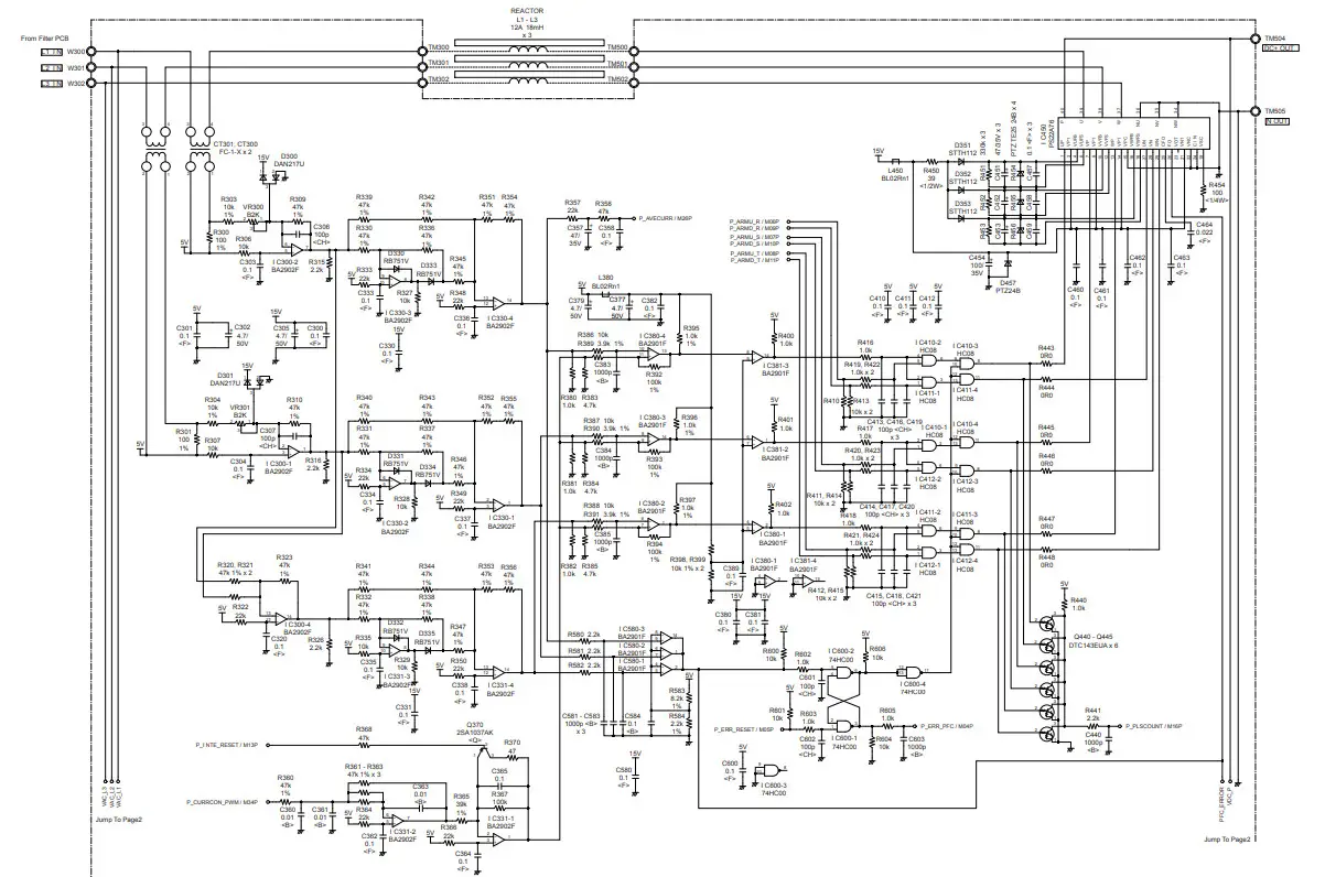 OUTDOOR UNIT
ACTIVE FILTER PCB – 2
K11BZ-1100HUE-AF0 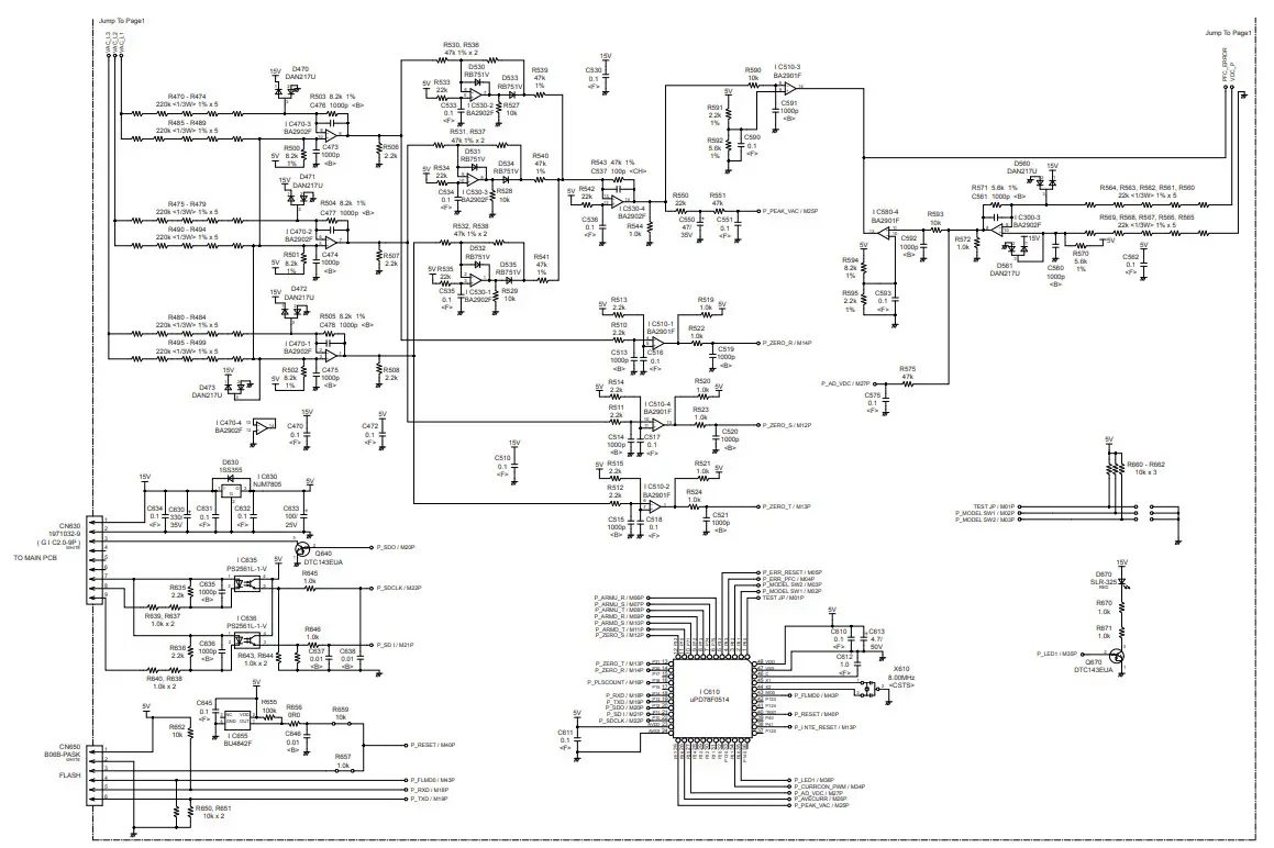 OUTDOOR UNIT
FILTER PCB
K07AQ-0700HUE-FL0 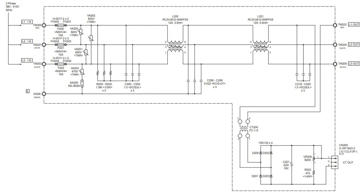
OUTDOOR UNIT
CAPACITOR PCB
K07AP-0700HUE-P0 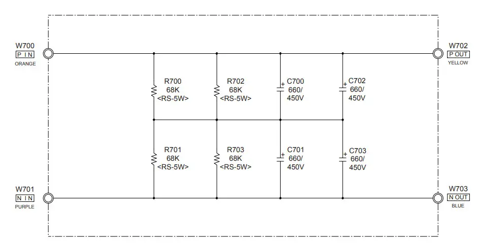
ERROR DETECTION
WIRED REMOTE CONTROL
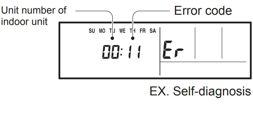
This is possible only on a wired remote control.
If an error occurs, the following display will be shown.
(“Er” will appear in the set room temperature display.)
![]() : 0.5s on / 0.5s off
: 0.5s on / 0.5s off![]() : 0.1s on / 0.1s off
: 0.1s on / 0.1s off
( ) : Number of flashing
Code | Description |
| Serial communication error | |
| Wired remote control communication error | |
| Check run unfinished | |
| Unit number or Refrigerant circuit address setting error [Simultaneous Multi] | |
| Indoor unit capacity error | |
| Combination error | |
| • Connection unit number error (indoor slave unit) [Simultaneous Multi] • Connection unit number error (indoor unit or branch unit) [Flexible Multi] | |
| Master unit, slave unit set-up error [Simultaneous Multi] | |
| Power supply interruption error | |
| Indoor unit PCB model information error | |
| Manual auto switch error | |
| Room temp. sensor error | |
| Indoor unit Heat Ex. Middle temp. sensor error | |
| Indoor unit fan motor error | |
| Drain pump error | |
| Damper error | |
| Indoor unit error | |
| Outdoor unit main PCB model information error or communication error | |
| Inverter error | |
| Active filter error, PFC circuit error | |
| Trip terminal L error | |
| Display PCB microcomputers communication error |
| Discharge temp. sensor error | |
| Compressor temp. sensor error | |
| Outdoor unit Heat Ex. liquid temp. sensor error | |
| Outdoor temp. sensor error | |
| Suction gas temp. sensor error | |
| • 2-way valve temp. sensor error • 3-way valve temp. sensor error | |
| Heat sink temp. sensor error | |
| • Sub-cool Heat Ex. gas inlet temp. sensor error • Sub-cool Heat Ex. gas outlet temp.sensor error | |
| Liquid pipe temp. sensor error | |
| Current sensor error | |
| • Discharge pressure sensor error • Suction pressure sensor error • High pressure switch error | |
| Trip detection | |
| Compressor rotor position detection error (permanent stop) | |
| Outdoor unit fan motor 1 error | |
| Outdoor unit fan motor 2 error | |
| 4-way valve error | |
| Coil (expansion valve) error | |
| Discharge temp. error | |
| Compressor temp. error | |
| High pressure error | |
| Low pressure error | |
| Branch boxes error [Flexible Multi] |
OUTDOOR UNIT
TEST RUN![]() CAUTION
CAUTION
Always turn on the power 6 hours prior to the start of the operation in order to protect the compressor.
1. Check items before performing the test run Make sure to perform the test run.
Before performing the test run, be sure to check the following points.
- Is gas leaking?
Check connection of each pipe (flare connection part, brazing part). - Is a breaker installed to the power cable of the outdoor unit ?
- Has each cable been securely connected to the terminal according to the specifications ?
- Are the 3-way valves (gas pipes and liquid pipes) of the outdoor units open?
- Has the power been supplied to the unit for at least 6 hours ?
- Has the necessary local setting been done ?
- Check insulation resistance of 1 M or more using a 500V mega tester.
If no problems are found with the above items, perform the test run according to “Test run method”.
If any problems are found, immediately resolve the problem and re-check the items.
2. Test run method![]() CAUTION
CAUTION
If the test run is performed for 1 outdoor unit in a group control system installation, the test run will also be performed for the other units. Therefore, make sure that all of the units have been installed before starting a test run.
(Group control system installation described in “SPECIAL INSTALLATION METHODS” in the installation manual of the indoor unit.)
Operate [ENTER] (TEST RUN) switch on the display board by the following procedure.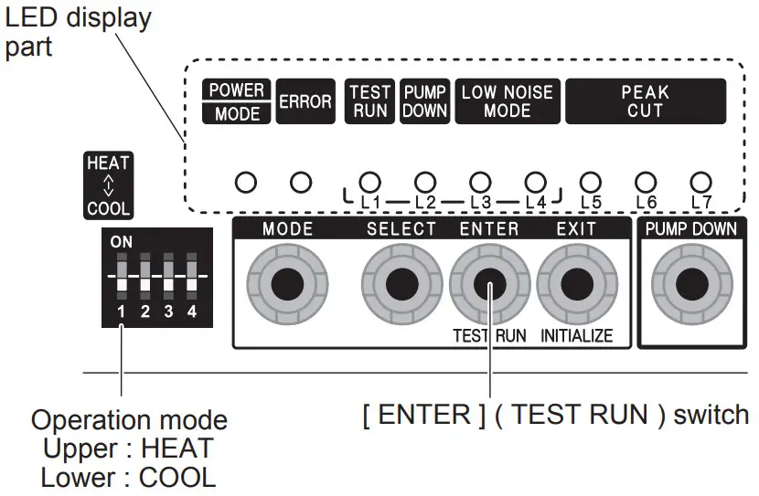
2.1. Operating procedures for the test run
(1) Check the 3-way valves (both at the liquid side and gas side) are opened.
(2) Set the operation mode to “COOL” or “HEAT”.
| POWER | ERROR | TEST RUN (L1) | PUMP DOWN (L2) | LOW NOISE (L3) (L4) | PEAK CUT (L5) (L6) (L7) | |||
| MODE | ||||||||
In the first test run, be sure to set the operation mode to “COOL”.
The operation mode cannot be switched between “COOL” and “HEAT” during the test run. To switch the operation mode between “COOL” and “HEAT”, stop the test run, switch the operation mode, and then start the test run again.
(3) Press [ENTER] (TEST RUN) switch for more than 3 seconds.
| POWER | ERROR | TEST RUN (L1) | PUMP DOWN (L2) | LOW NOISE (L3) (L4) | PEAK CUT (L5) (L6) (L7) | |||
| MODE | ||||||||
“TEST RUN” LED will light on.
If the compressor is operating at starting the test run, the compressor will stop and, after a while, the test run will start.
Either of the above “LOW NOISE” or “PEAK CUT” will light on during the test run if local setting function is selected.
(4) Confirm operating status.
(5) Press [ENTER] (TEST RUN) switch again.
| POWER | ERROR | TEST RUN (L1) | PUMP DOWN (L2) | LOW NOISE (L3) (L4) | PEAK CUT (L5) (L6) (L7) | |||
| MODE | ||||||||
“TEST RUN” LED lights off, and TEST RUN stops.
Test run will finish after about 60 minutes automatically.
At the same time, “TEST RUN” LED will light off.
Test run may be stopped before operating for 60 minutes if an error occurs after a starting test run.
OUTDOOR UNIT ERROR CODE DISPLAY
Display when an error occurs
| POWER | ERROR | TEST RUN (L1) | PUMP DOWN (L2) | LOW NOISE (L3) (L4) | PEAK CUT (L5) (L6) (L7) | |||
| MODE | ||||||||
| Blinks (Hi-speed) | ||||||||
Check that the ERROR LED blinks, and then short-press the [ENTER] switch once.
The number of blinks of the LED indicates the type of error.
Display mode![]() : ON
: ON![]() : OFF
: OFF![]() : Blink (0.5s ON / 0.5s OFF)
: Blink (0.5s ON / 0.5s OFF)
( ) : Number of ßashing
Error code check table
| POWER | ERROR | TEST RUN (L1) | PUMP DOWN (L2) | LOW NOISE (L3) (L4) | PEAK CUT (L5) (L6) (L7) | Description | |||
| MODE | |||||||||
| Serial forward transmission error immediately after operation | |||||||||
| (1) | Serial forward transmission error during operation | ||||||||
| Indoor unit capacity error | |||||||||
| Indoor unit error | |||||||||
| Over voltage | |||||||||
| (1) | Power supply frequency error | ||||||||
| Outdoor unit PCB model information error | |||||||||
| Inverter communication error | |||||||||
| PFC communication error | |||||||||
| Inverter error | |||||||||
| PFC AD detection error | |||||||||
| PFC hardware error | |||||||||
| IPM error (Trip terminal L error) | |||||||||
| Rush current limiting resister temp rise protection | |||||||||
| Discharge temp. sensor error | |||||||||
| Compressor temp. sensor error | |||||||||
| Heat Ex. middle temp. sensor error | |||||||||
| Outdoor unit Heat Ex. liquid temp. sensor error | |||||||||
| Outdoor temp. sensor error | |||||||||
| Heat sink temp. sensor error | |||||||||
| PFC heat sink temp. sensor error | |||||||||
| Current sensor 1 error (stoppage permanently) | |||||||||
| High pressure switch 1 error | |||||||||
| Pressure sensor error | |||||||||
| Trip detection (stoppage permanently) | |||||||||
| Compressor motor control error (stoppage permanently) | |||||||||
| Compressor motor loss of synchronization (stoppage permanently) | |||||||||
| Outdoor unit fan motor 1 error (Duty error) | |||||||||
| Outdoor unit fan motor 2 error (Duty error) | |||||||||
| 4-way valve error | |||||||||
| Discharge temp. 1 error (stoppage permanently) | |||||||||
| Compressor 1 temp. error (stoppage permanently) | |||||||||
| Low pressure error | |||||||||
OUTDOOR UNIT
PUMP DOWN (Refrigerant collecting operation)
Perform the following procedures to collect the refrigerant when moving the indoor unit or outdoor unit![]() WARNING
WARNING
Never touch electrical components such as the terminal blocks or reactor except the switch on the display board.
It may cause a serious accident such as electric shock.![]() CAUTION
CAUTION
Perform the pump down operation before disconnecting any refrigerant pipe or electric cable.
Collect refrigerant from the service port or the 3-way valve if pump down cannot be performed.
In case of a group control system installation, do not turn the power off pump down is completed in all outdoor units.
(Group control system installation described in “SPECIAL INSTALLATION METHODS” in the installation manual of the indoor unit.)
Operate [PUMP DOWN] switch on the display board in the manner described below.
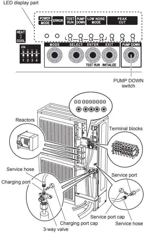
1. Preparation for pump down
Confirm that the power is off, and then open the service panel.
2. Pump down procedure
(1) Check the 3-way valves (both at the liquid side and gas side) are opened.
(2) Turn the power on.
| POWER | ERROR | TEST RUN (L1) | PUMP DOWN (L2) | LOW NOISE (L3) (L4) | PEAK CUT (L5) (L6) (L7) | |||
| MODE | ||||||||
(3) Press [PUMP DOWN] switch for 3 seconds or more after 3 minutes after power on.
| POWER | ERROR | TEST RUN (L1) | PUMP DOWN (L2) | LOW NOISE (L3) (L4) | PEAK CUT (L5) (L6) (L7) | |||
| MODE | ||||||||
LED display lights on as shown in the above figure, and the fans and the compressor start operating.
If the [PUMP DOWN] switch is pressed while the compressor is operating, the compressor will stop, then start again in about 3 minutes.
(4) LED display will change as shown below about 3 minutes after the compressor starts. Fully close the 3-way valve on the liquid pipe side at this stage.
| POWER | ERROR | TEST RUN (L1) | PUMP DOWN (L2) | LOW NOISE (L3) (L4) | PEAK CUT (L5) (L6) (L7) | |||
| MODE | ||||||||
If the valve on the liquid pipe side is not closed, the pump down cannot be performed.
(5) When LED display changes as shown in the below figure, close the 3-way valve on the gas pipe side tightly.
| POWER | ERROR | TEST RUN (L1) | PUMP DOWN (L2) | LOW NOISE (L3) (L4) | PEAK CUT (L5) (L6) (L7) | |||
| MODE | ||||||||
If the valve on the gas pipe side is not closed, refrigerant may flow into the piping after the compressor stops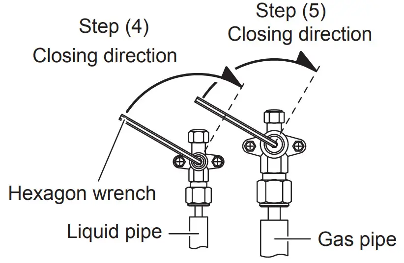 (6) LED display changes after 1 minute as shown in the figure below
| POWER | ERROR | TEST RUN (L1) | PUMP DOWN (L2) | LOW NOISE (L3) (L4) | PEAK CUT (L5) (L6) (L7) | |||
| MODE | ||||||||
Fans and compressor stop automatically.
If the pump down is successfully completed (the above LED display is shown), the outdoor unit remains stopped until the power is turned off.
(7) Turn the power off.
| POWER | ERROR | TEST RUN (L1) | PUMP DOWN (L2) | LOW NOISE (L3) (L4) | PEAK CUT (L5) (L6) (L7) | |||
| MODE | ||||||||
PUMP DOWN is completed.
(Note)
To stop pump down, press the [PUMP DOWN] switch again.
To start the pump down again after the compressor is automatically stopped due to an error, turn the power off and open the 3-way valves. Wait 3 minutes, turn the power on and start the pump down again.
When starting the operation after completion of the pump down, turn the power off, and then open the 3-way valves. Wait 3 minutes, turn the power on and perform a test run in the “COOL” operation mode.
PARTS
INDOOR UNIT
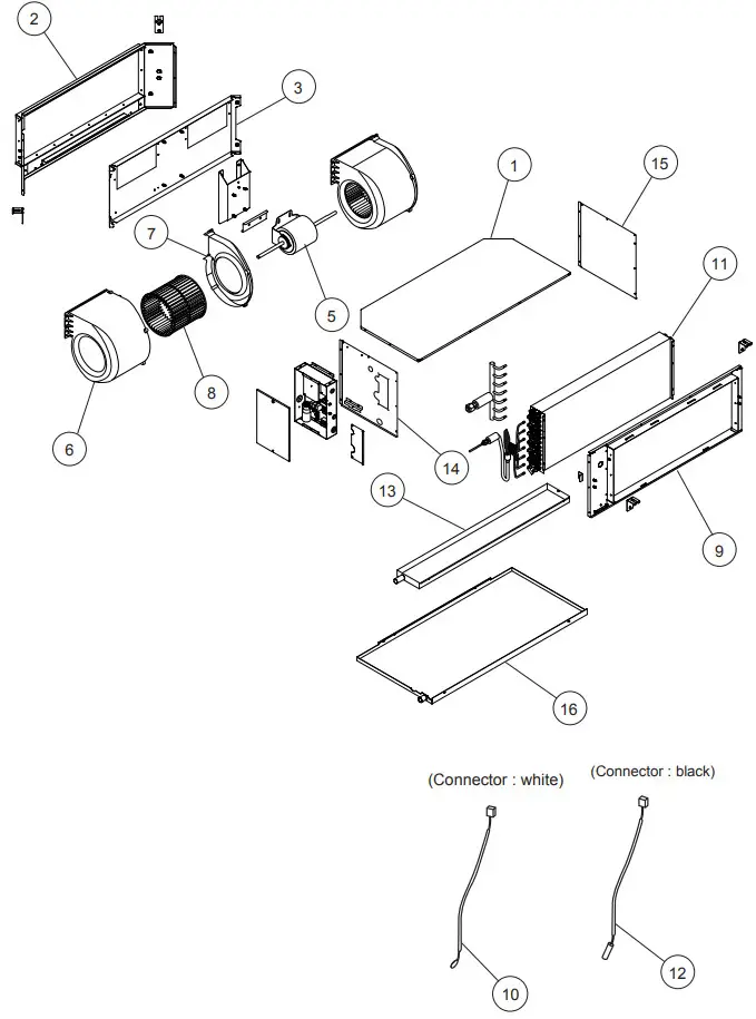
Ref. | Description | Parts number |
| 1 | Plate Top Sub Assy | 9372576014 |
| 2 | Kit (Panel Front Sub Assy) | 9372637029 |
| 3 | Panel Fan Assy | 9372035009 |
| 5 | Motor, Induct | 9602802012 |
| 6 | Casing A | 9372057018 |
| 7 | Casing B | 9372058015 |
| 8 | Sirocco Fan | 9372059029 |
| 9 | Kit (Panel Rear Sub Assy) | 9372636022 |
| 10 | Room Thermistor | 9703299216 |
| 11 | Evaporator Sub Assy | 9372584057 |
| 12 | Pipe Thermistor | 9703297113 |
| 13 | Drain Pan Assy | 9372579015 |
| 14 | Kit (Panel Right Sub Assy) | 9372916025 |
| 15 | Kit (Panel Left Sub Assy) | 9372581018 |
| 16 | Drain Pan S Sub Assy | 9372582015 |
INDOOR UNIT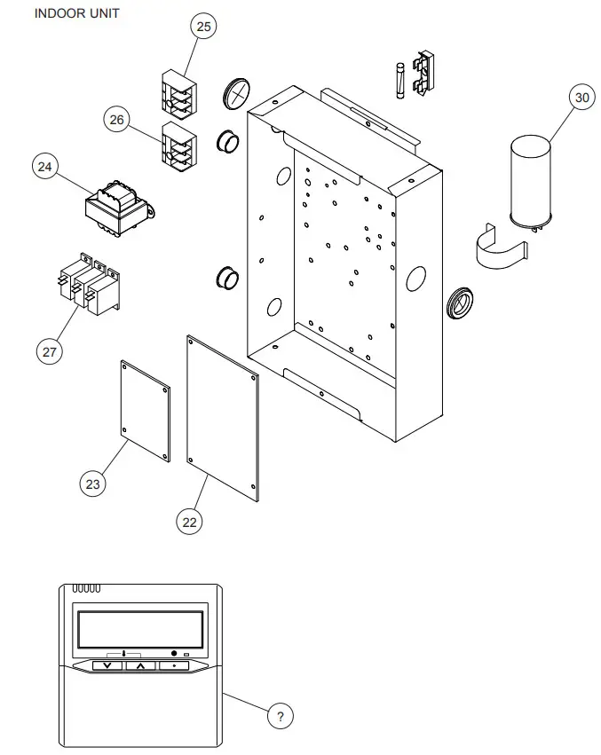
Ref. | Description | Parts number |
| 22 | Power Supply PCB | 9705668119 |
| 23 | Main PCB (45) | 9705246287 |
| 23 | Main PCB (54) | 9705246294 |
| 24 | Transformer (Power) | 9704129017 |
| 25 | Terminal 3P | 9703345012 |
| 26 | Terminal 3P | 9306489045 |
| 27 | Relay | 9900294014 |
| 30 | Capacitor, Plastic | 9900269111 |
| ? | Remote Control | 9318593013 |
PARTS
OUTDOOR UNIT
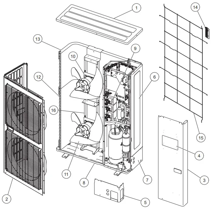
| Ref. | Description | Parts number |
| 1 | Top Panel Sub Assy | 9374417032 |
| 2 | Front Panel Sub Assy | 9374414130 |
| 3 | Sevice Panel Sub Assy | 9374415076 |
| 4 | Emblem Rear | 9351355005 |
| 5 | Pipe Cover Front | 9378861015 |
| 6 | Right Panel | 9378863019 |
| 7 | Pipe Cover Rear | 9378862012 |
| 8 | Base Assy | 9374166220 |
| 9 | Reactor Assy | 9900641016 |
| 10 | Motor, DC Brushless | 9602843046 |
| 11 | Propeller Fan Assy | 9366378020 |
| 12 | Condenser A Sub Assy | 9374420261 |
| 13 | Condenser B Sub Assy | 9374422081 |
| 14 | Thermo Holder | 9375211011 |
| 15 | Protective Net | 9375381042 |
| 16 | Motor Bracket Sub Assy | 9374418145 |
OUTDOOR UNIT
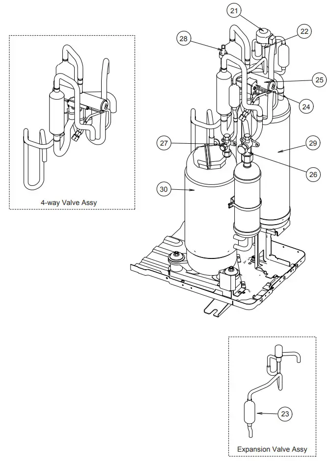
Ref. | Description | Parts number |
| 21 | Expansion Valve Coil | 9900190057 |
| 22 | Expansion Valve Assy | 9370947182 |
| 23 | Strainer Assy | 9372524039 |
| 24 | Solenoid | 9970113024 |
| 25 | 4-way Valve Assy | 9374425273 |
| 26 | 3-way Valve Assy | 9379079006 |
| 27 | 3-way Valve Assy | 9379077002 |
| 28 | Sensor | 9900505011 |
| 29 | Accumulator Assy | 9375250096 |
| 30 | Compressor Assy | 9383162008 |
OUTDOOR UNIT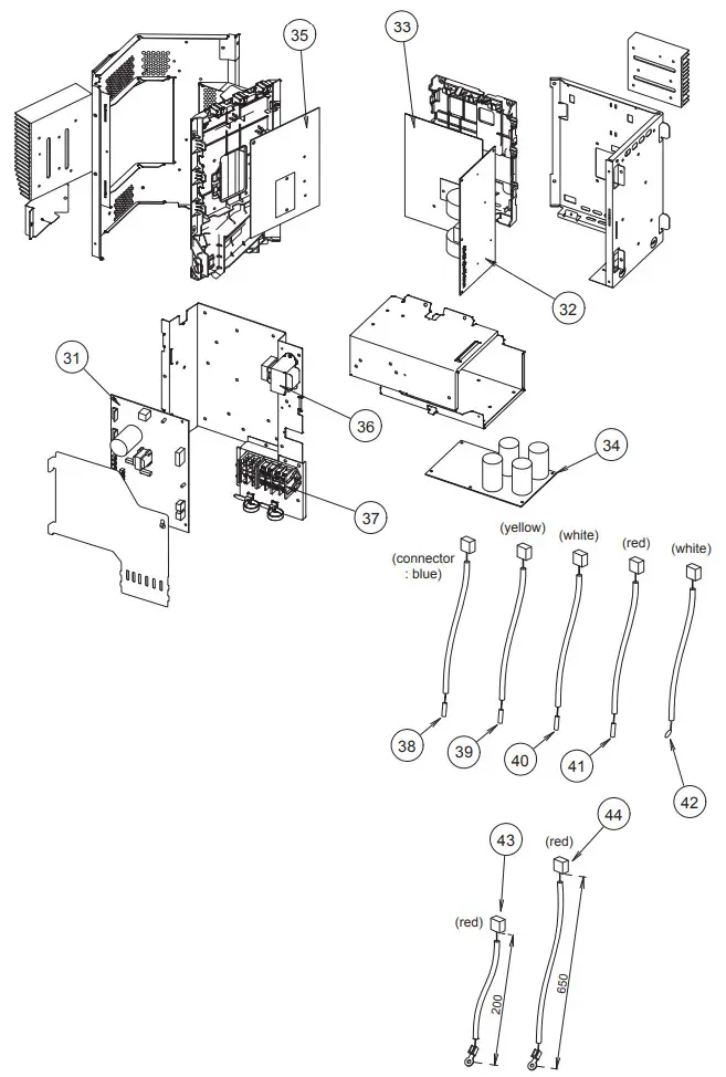
Ref. | Description | Parts number |
| 31 | Main PCB (45) | 9707627077 |
| 31 | Main PCB (54) | 9707627084 |
| 32 | Filter PCB | 9707609011 |
| 33 | Active Filter PCB with grease | 9709680438 |
| 34 | Capacitor PCB | 9707608014 |
| 35 | Transistor PCB with grease | 9709680445 |
| 36 | Reactor Assy | 9900481018 |
| 37 | Terminal | 9900428082 |
| 38 | Compressor Thermistor | 9900516000 |
| 39 | Discharge Thermistor | 9900515003 |
| 40 | Thermistor (Heat Exchanger Mid) | 9900513009 |
| 41 | Thermistor (Heat Exchanger Out) | 9900514006 |
| 42 | Outdoor Thermistor | 9900517007 |
| 43 | Heatsink Thermistor (Inverter) | 9900518011 |
| 44 | Heatsink Thermistor (PFC) | 9900518028 |
ACCESSORIES
INDOOR UNIT
| Name and Shape | Q’ty | Application | Part number |
| Special nut A (large flange) | 4 | For suspending the indoor unit from ceiling | 313005446653 |
| Special nut B (small flange) | 4 | 313005446759 | |
| Coupler heat insulation (large) | 1 | For indoor side pipe joint (large pipe) | 9378173569 |
| Coupler heat insulation (small) | 1 | For indoor side pipe joint (small pipe) | 9378173521 |
| Cable tie | 1 | Fixing the remote cord | 313361275805 |
| Remote control | 1 | For air conditioner operation | 9318593013 |
| Remote control cord | 1 | For connecting the remote control | 9372714010 |
| Tapping screw (ø4 × 16) | 2 | For installing the remote control | 0700181108 |
OUTDOOR UNIT
Name and Shape | Q’ty | Application | Part number |
| Drain pipe | 1 | For drain piping work | 9303029015 |
| Drain cap | 2 | 313166024302 | |
| One-touch bush | 2 | For power supply cable and connection cable installation | 9378779013 |
OPTIONAL PARTS
Parts name | Model No. | Application |
| Simple remote control | UTY-RSNYM | For air conditioner operation |
| Wired remote control | UTY-RNNYM | For air conditioner operation |
| Remote sensor unit | UTY-XSZX | Room temperature sensor |
| External connect kit | UTD-ECS5A | For control input/output port |
| Long life filter | UTD-LF60KA |
1204G4043


