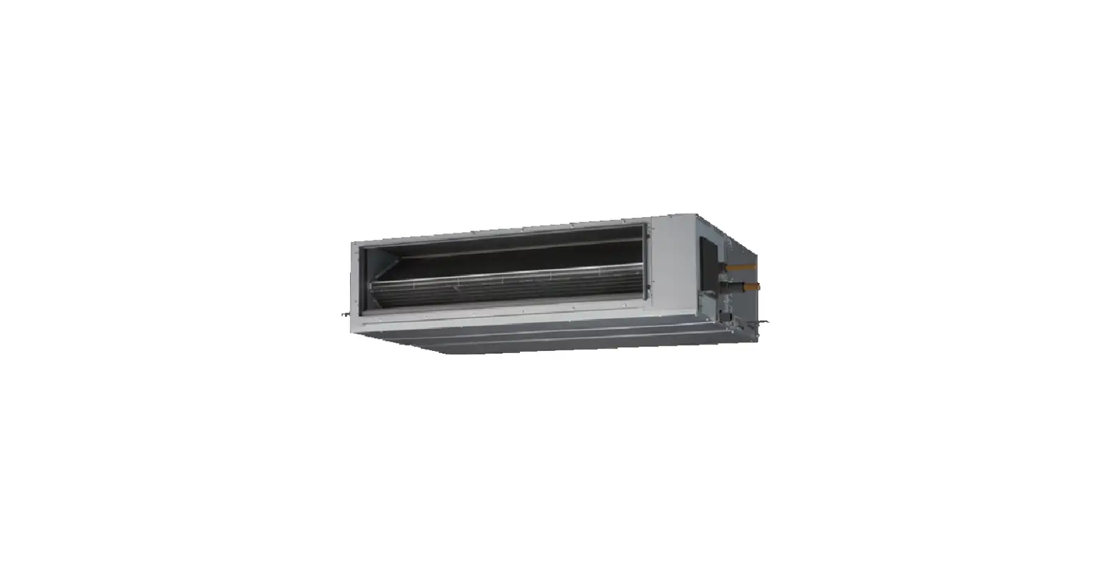
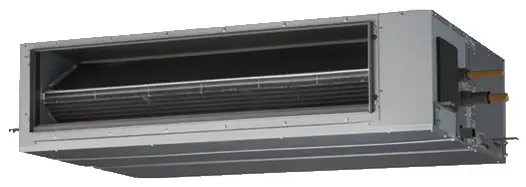
FUJITSU ARYA30LBTU Split Type Air Conditioner Duct Type
Product Specifications
- Type: Cooling & Heating
- Cooling Capacity: 8.5 kW (for ARYA30LBTU) and 9.4 kW (for ARYA36LBTU
- Heating Capacity: 10.0 kW (for ARYA30LBTU) and 11.2 kW (for ARYA36LBTU)
- Power Source: 230 V, 50 Hz
- Cooling Running Current: 11.6 A (for ARYA30LBTU) and 12.8 A (for ARYA36LBTU)
- Heating Running Current: 11.7 A (for ARYA30LBTU) and 13.6 A (for ARYA36LBTU)
- Input Watts (Cooling): 2.65 kW (for ARYA30LBTU) and 2.93 kW (for ARYA36LBTU)
- Input Watts (Heating): 2.68 kW (for ARYA30LBTU) and 3.10 kW (for ARYA36LBTU)
- E.E.R. (Cooling): 3.21 kW/kW
- E.E.R. (Heating): 3.73 kW/kW (for ARYA30LBTU) and 3.61 kW/kW (for ARYA36LBTU)
- Starting Current: 15 A
- Moisture Removal: 2.5 L/hr (for ARYA30LBTU) and 3.0 L/hr (for ARYA36LBTU)
- Air Circulation (Indoor): 2,100 m3/hr
- Air Circulation (Outdoor): 3,600 m3/hr (for ARYA30LBTU) and 4,000 m3/hr (for ARYA36LBTU)
- Maximum Current: 17.0 A (for ARYA30LBTU) and 20.0 A (for ARYA36LBTU)
- Fan Speed (Indoor Unit): Discrimination – High speed, Me speed, Low speed, Quiet
- Fan Speed (Outdoor Unit): Discrimination – Speed
- Noise Level: 42 dB (High speed), 37 dB (Med speed), 32 dB (Low speed), 29 dB (Quiet) for Indoor Unit; 53 dB (Cooling), 55 dB (Heating) for Outdoor Unit
- Compressor Type: Hermetic type, Inverter, 4 poles, 3 phase, DC motor, Twin Rotary
- Compressor Weight (with oil): 16.3 kg
- Standard Refrigerant: 2,100 g
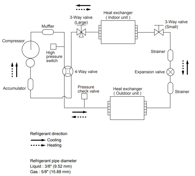
- Refrigerant Type: R410A
- Max Pipe Length: 50 m
- Max Pipe Height: 30 m
Product Usage Instructions
The Split Type Air Conditioner Duct Type is designed to provide cooling and heating in a room. To use the product, follow the steps below:
- Install the indoor unit and outdoor unit in their respective locations.
- Connect the indoor and outdoor units with refrigerant pipes and electrical cables.
- Connect the indoor unit to a power source of 230 V, 50 Hz.
- Turn on the power and select the desired mode (cooling or heating) using the remote control provided.
- Adjust the temperature and fan speed using the remote control as per your requirement.
- When not in use, turn off the power and unplug the device from the power source.
- Regularly clean the air filters to maintain optimal performance of the product.
SPECIFICATIONS
ELECTRICAL DATA
| TYPE | Cooling & Heating | ||
| INDOOR UNIT | ARYA30LBTU | ARYA36LBTU | |
| OUTDOOR UNIT | AOYA30LBTL | AOYA36LBTL | |
| COOLING CAPACITY | 8.5 kW | 9.4 kW | |
| HEATING CAPACITY | 10.0 kW | 11.2 kW | |
| POWER SOURCE | 230 V 50 Hz | 230 V 50 Hz | |
| RUNNING CURRENT | Cooling | 11.6 A | 12.8 A |
| Heating | 11.7 A | 13.6 A | |
| INPUT WATTS | Cooling | 2.65 kW | 2.93 kW |
| Heating | 2.68 kW | 3.10 kW | |
| E.E.R. | Cooling | 3.21 kW/kW | 3.21 kW/kW |
| Heating | 3.73 kW/kW | 3.61 kW/kW | |
| STARTING CURRENT | 15 A | 15 A | |
| MOISTURE REMOVAL | 2.5 L/hr | 3.0 L/hr | |
| AIRCIRCULATION INDOOR | 2,100 m3/hr | 2,100 m3/hr | |
| AIRCIRCULATION OUTDOOR | 3,600 m3/hr | 4,000 m3/hr | |
| MAXIMUM CURRENT | 17.0 A | 20.0 A | |
FAN SPEED
|
INDOOR UNIT | Discrimination | MFG-45RVN | MFG-45RVN |
| High speed | 1,270 r.p.m. | 1,270 r.p.m. | |
| Med speed | 980 r.p.m. | 980 r.p.m. | |
| Low speed | 790 r.p.m. | 790 r.p.m. | |
| Quiet | 630 r.p.m. | 630 r.p.m. | |
| OUTDOOR UNIT | Discrimination | MFE-36TV | MFE-36TV |
| Speed | 850 r.p.m. | 950 r.p.m. |
NOISE LEVEL
|
INDOOR UNIT | High speed | 42 dB | 42 dB |
| Med speed | 37 dB | 37 dB | |
| Low speed | 32 dB | 32 dB | |
| Quiet | 29 dB | 29 dB | |
| OUTDOOR UNIT | Cooling | 53 dB | 54 dB |
| Heating | 55 dB | 55 dB |
Note : Static pressure : 47Pa Duct length : Inlet 1m, Outlet 2m
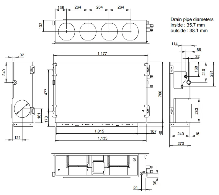
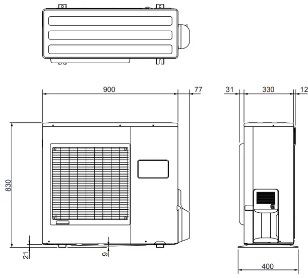
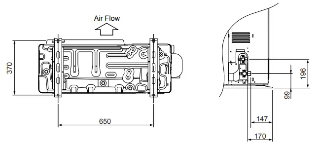
DIMENSIONS
| INDOOR UNIT H x W x D | 270 x 1,135 x 700 mm |
| OUTDOOR UNIT H x W x D | 830 x 900 x 330 mm |
WEIGHT
| INDOOR UNIT Gross / Net | 47 kg / 40 kg |
| OUTDOOR UNIT Gross / Net | 70 kg / 62 kg |
COMPRESSOR AND REFRIGERANT
| COMPRESSOR TYPE | Hermetic type, Inverter, 4 poles, 3 phase, DC motor, Twin Rotary | |
| DISCRIMINATION | 5KD240XAD21 | |
| WEIGHT (with oil) | 16.3 kg | |
| STANDARD REFRIGERANT | 2,100 g | |
| REFRIGERANT TYPE | R410A | |
| MAX PIPE LENGTH | 50 m | |
| MAX PIPE HEIGHT | 30 m | |
| Pipe length FULL CHARGE | 20 m | 2,100 g |
| 30 m | 2,500 g | |
| 40 m | 2,900 g | |
| 50 m | 3,300 g | |
| ADDITIONAL CHARGE | 40 g/m | |
DIMENSIONS
INDOOR UNIT
OUTDOOR UNIT
REFRIGERANT SYSTEM DIAGRAM
CIRCUIT DIAGRAM
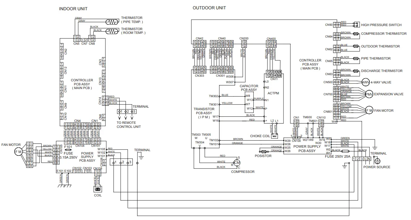
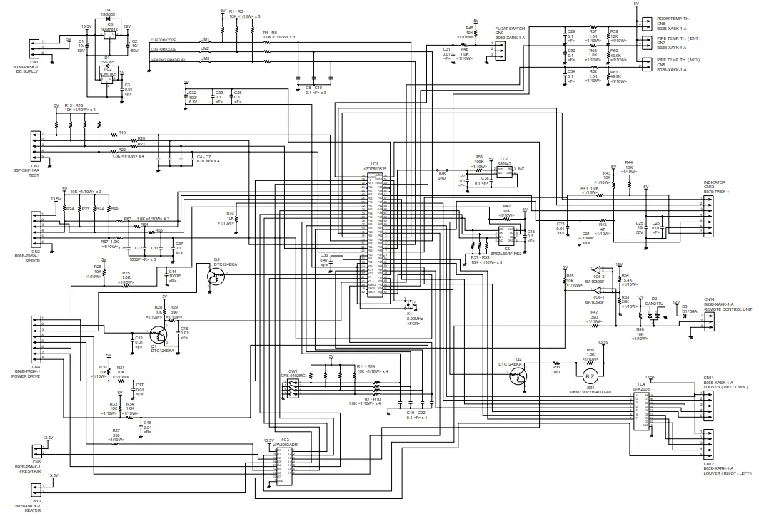
INDOOR PCB CIRCUIT DIAGRAM
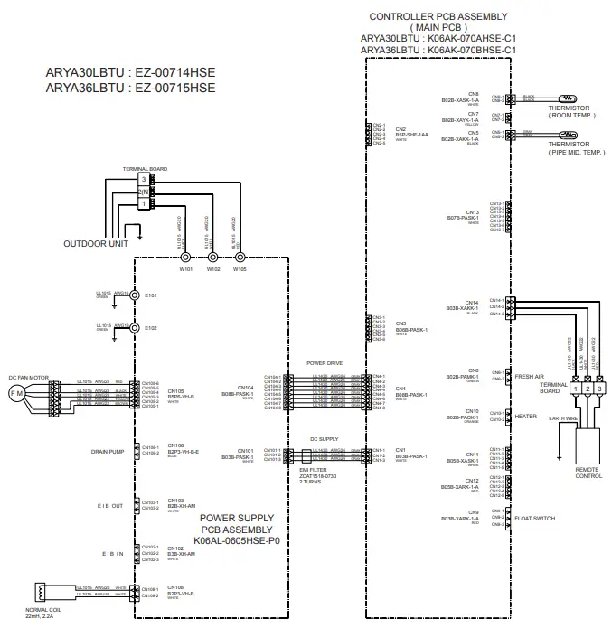
CONTROLLER PCB ASSEMBLY ( MAIN PCB )
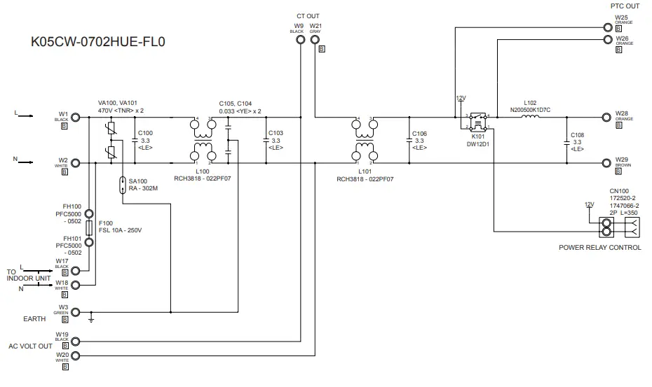
POWER SUPPLY PCB ASSEMBLY

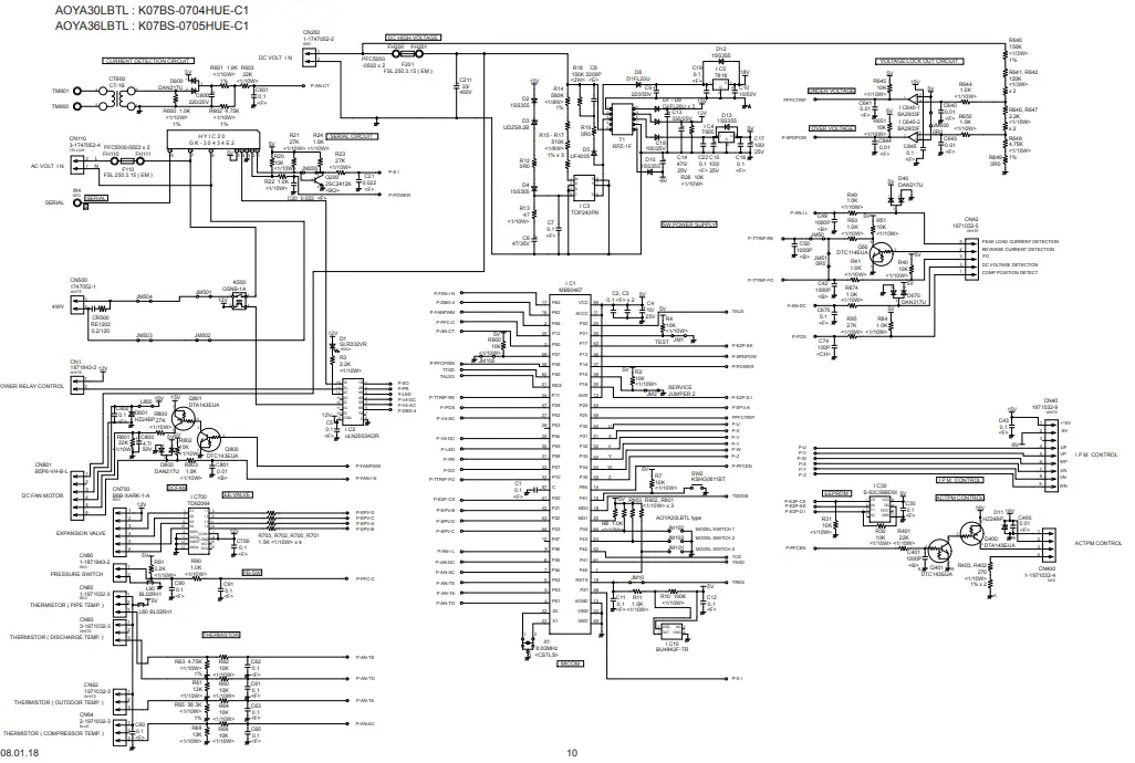
OUTDOOR PCB CIRCUIT DIAGRAM
INVERTER ASSEMBLY
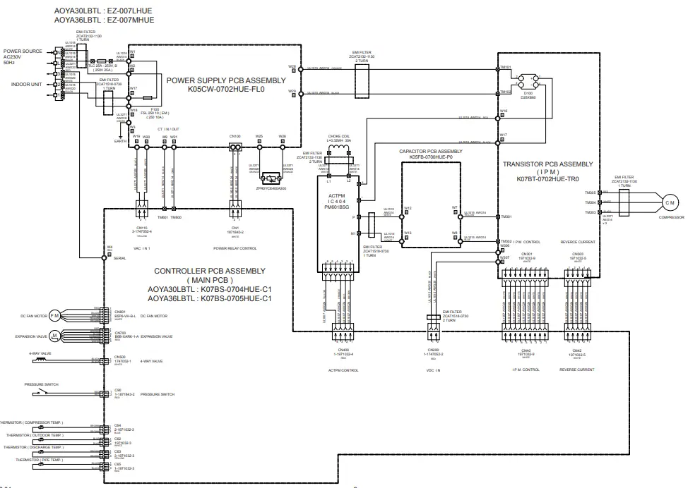
CONTROLLER PCB ASSEMBLY ( MAIN PCB )
TRANSISTOR PCB ASSEMBLY
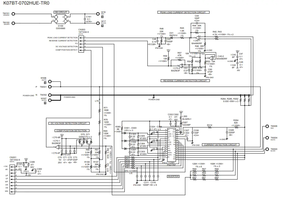
POWER SUPPLY PCB ASSEMBLY
CONDENSOR PCB ASSEMBLY
ERROR CONTENTS
REMOTE CONTROL UNIT
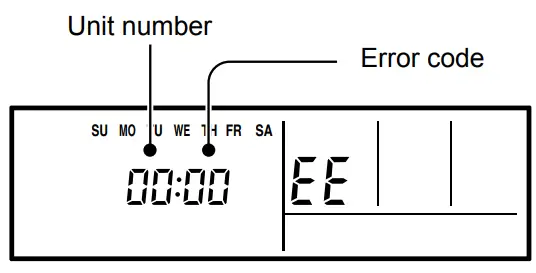
- Troubleshooting at the remote control LCD
- This is possible only on the wired remote control.
- If an error occurs, the following display will be shown.(“EE” will appear in the set room temperature display.)

Code Error contents 01 13 26 27
Indoor signal error
00 Wired remote controller abnormal 02 Indoor room temperature sensor error 04 Indoor heat exchanger temperature sensor (middle) error 28 Indoor heat exchanger temperature sensor (inlet) error 09 Float switch operated 0C Outdoor discharge pipe temperature sensor error 06 Outdoor heat exchanger temperature sensor (outlet) error 0A Outdoor temperature sensor error 15 Compressor temperature sensor error 1d 2-way valve temperature sensor error 1E 3-way valve temperature sensor error 29 Outdoor heat exchanger temperature sensor (middle) error 20 Indoor manual auto switch abnormal 2A Power supply frequency detection error 17 IPM protection 18 CT error 1A Compressor location error 1b Outdoor fan error 1F Connected indoor unit abnormal 1c Outdoor unit computer communication error 12 Indoor fan abnormal 0F Discharge temperature error 24 Exessive high pressure protection on cooling 2c 4-way valve abnormal 16 Pressure switch abnormal 2b Compressor temperature error 19 Active filter abnormal 25 PFC circuit error
ERROR CONTENTS
OUTDOOR UNIT
CAUTION
Always turn on the power 12 hours prior to the start of the operation in order to ensure compressor protection
- Make a TEST RUN in accordance with the installation instruction sheet for the indoor unit.
- OUTDOOR UNIT LEDS
When a malfunction occurs in the outdoor unit, the LED on the circuit board lights to indicate the error. Refer to the following table for the de-scription of each error according to the LED.LED ERROR CONTENTS FLASH (0.1sec ON/0.1sec OFF) Temperature sensor error FLASH (0.5sec ON/0.5sec OFF) IPM protection FLASH (2sec ON/2sec OFF) Current trans. error FLASH (5sec ON/5sec OFF) Outdoor fan error FLASH (0.1sec ON/2sec OFF)
Compressor rotor position cannot be detected FLASH (5sec ON/0.1sec OFF) ACTPM error Lighting
Overheat discharge temperature protection
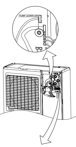
SPECIAL INSTALLATION SETTING
PUMP DOWN (Refrigerant collecting operation)
Perform the following procedures to collect the refrigerant when moving the indoor unit or the outdoor unit.
- Press the push-button switch on the circuit board once.
- The LED on the circuit board starts flashing (one second ON/one se-cond OFF). This indicates the start of PUMP DOWN operation.
- When the switch is pressed while the compressor is in operation, PUMP DOWN operation starts automatically.
- When the switch is pressed while the compressor is in stop, the com-pressor starts to operate automatically, and then move on to PUMP DOWN operation.
- PUMP DOWN operation continues for about 1 minute. When PUMP DOWN operation is completed, the compressor stops automatically.
Then close the 2-way valve and 3-way valve immediately. - Turn the power off.

DANGER: This part (Choke coil) generates high voltages. Never touch this part.
PARTS
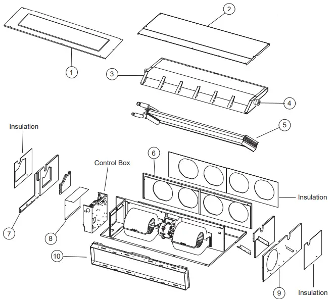
INDOOR UNIT
| Ref. | Description | Part number | |
| 1 | Intake Cover Sub Assy | 9374512010 | |
| 2 | Main Panel Sub Assy | 9374511013 | |
| 3 | Drain Pan Sub Assy | 9374513017 | |
| 4 | Drain Cap | 9356541007 | |
| 5 | Evaporator Total Assy | 9374517510 | |
| 6 | Outlet Panel Sub Assy | 9374510016 | |
| 7 | Cabinet R Sub Assy | 9374508020 | |
| 8 | Control Cover A Sub Assy | 9374516018 | |
| 9 | Cabinet L Sub Assy | 9374509010 | |
| 10 | Intake Frame Assy | 9374216017 | |
| — | Distributor Assy | 9371325439 | |
| — | Coupling Pipe Assy | 9371333052 | |
| — | Seal Panel Sub Assy | 9374515011 | |
| — | Bracket Pipe Sub Assy | 9374514014 | |
| — | Thermo Holder Pipe | 313714262805 | |
| — | Thermistor Spring A | 313728262708 |
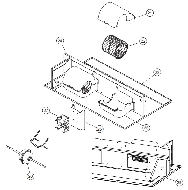
| Ref. | Description | Part number | |
| 21 | Casing B | 9374234011 | |
| 22 | Sirocco Fan Assy | 9356531046 | |
| 23 | Base Sub Assy | 9374504015 | |
| 24 | Separate Wall Assy | 9374228010 | |
| 25 | Casing A | 9374233014 | |
| 26 | Bracket Motor Assy | 9374230013 | |
| 27 | Motor Mount | 9378002012 | |
| 28 | Fan Motor | 9602466016 | |
| 29 | Bracket (Eva) R | 9374207015 | |
| — | Bracket (Eva) L | 9374208012 | |
| — | Panel (Control Box) | 9374210015 | |
| — | Cap (Power) | 9352173011 | |
| — | Motor Band | 9378031012 |
Control unit
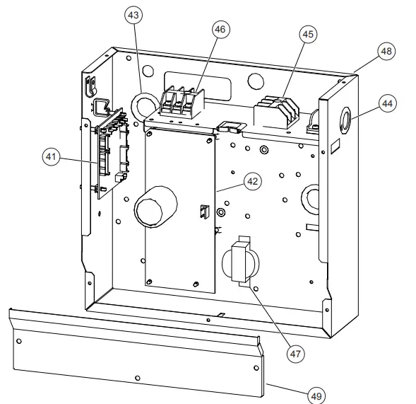
| Ref. | Description | Part number | |
| 41 | Controller PCB Assy (30) | 9707393293 | |
| 41 | Controller PCB Assy (36) | 9707393309 | |
| 42 | Power Supply PCB Assy | 9707398069 | |
| 43 | Cap (Power) | 9352173011 | |
| 44 | One Touch Bush | 9374407019 | |
| 45 | Terminal 3P | 9703345012 | |
| 46 | Terminal 3P | 9306489045 | |
| 47 | Reactor Assy | 9707457018 | |
| 48 | Control Box A | 9374219018 | |
| 49 | Control Cover B | 9374222018 | |
| — | Control Box B | 9374220014 | |
| — | Room Thermistor | 9703299025 | |
| — | Pipe Thermistor | 9703297021 | |
| — | Remote Control | 9372266199 | |
| — | Wire Assembly | 9372714010 |
OUTDOOR UNIT
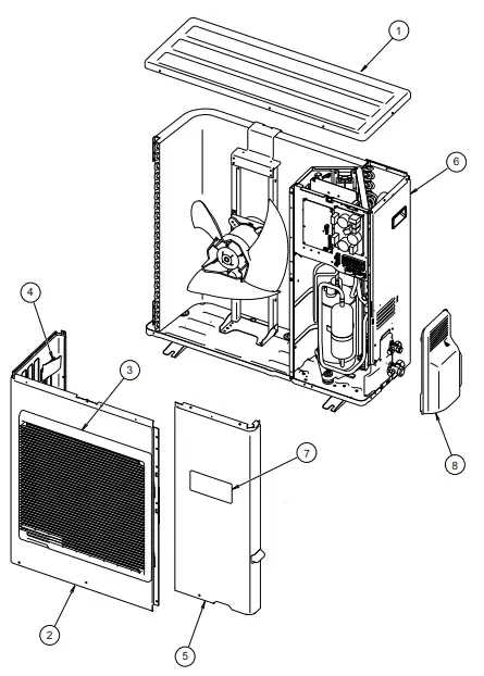
| Ref. | Description | Part number | |
| 1 | Top Panel Sub Assy | 9374417032 | |
| 2 | Front Panel | 9374094066 | |
| 3 | Fan Guard | 9374330010 | |
| 4 | Grip Side | 9374173013 | |
| 5 | Service Panel Sub Assy | 9374415052 | |
| 6 | Right Panel Sub Assy | 9374416127 | |
| 7 | Emblem Rear | 9351355005 | |
| 8 | Valve Cover | 9374174010 |
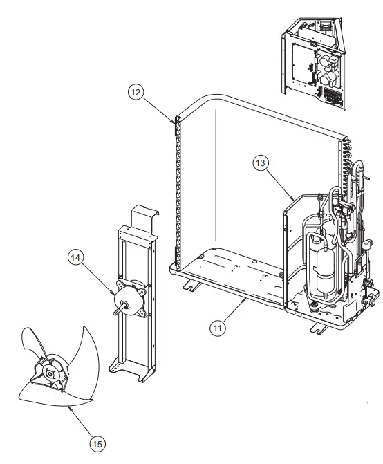
| 11 | Base Assy | 9374166138 | |
| 12 | Condenser A Sub Assy | 9374420230 | |
| 13 | Separate Wall | 9374413188 | |
| 14 | Fan Motor | 9602717019 | |
| 15 | Propeller Fan Assy | 9366378020 |
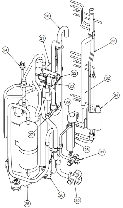
| 21 | Accumulator | 9385005006 | |
| 22 | 4-Way Valve | 9900164010 | |
| 23 | Solenoid | 9970055034 | |
| 24 | Pressure Switch | 9900186012 | |
| 25 | Compressor Assy | 9372558126 | |
| 26 | Accumulator Support Assy | 313986353804 | |
| 27 | Check Joint Assy | 9372802038 | |
| 28 | Expansion Valve Assy | 9370947144 | |
| 29 | Coil (Expansion Valve) | 9900057039 | |
| 30 | 3-Way Valve Assy | 9377959010 | |
| 31 | 3-Way Valve Assy | 9377958013 | |
| 32 | Inlet Pipe (Cond) A Assy | 9373461067 | |
| 33 | Outlet Pipe (Cond) A Assy | 9374266104 | |
| 34 | Strainer Assy | 9372524015 |
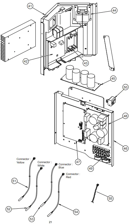
| Ref. | Description | Part number | |
| 41 | Inverter Case | 9375314019 | |
| 42 | TR PCB Assy (IPM) | 9707669039 | |
| 43 | ACTPM | 9707592016 | |
| 44 | Choke Coil | 9900366018 | |
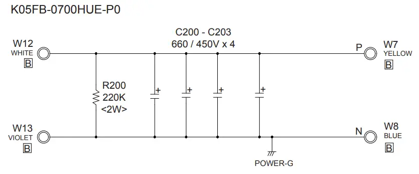
| 45 | Capacitor PCB Assy | 9707257021 | |
| 46 | PCB Case Assy | 9375316020 | |
| 47 | Controller PCB Assy (30) | 9707667059 | |
| 47 | Controller PCB Assy (36) | 9707667066 | |
| 48 | Power Supply PCB Assy | 9707128161 | |
| 49 | Terminal | 9900203023 | |
| 50 | Thermistor | 9704265012 | |
| 51 | Discharge Thermitor | 9900461003 | |
| 52 | Thermistor (Outdoor) | 9900463007 | |
| 53 | Compressor Thermistor | 9900466008 | |
| 54 | Heat Exchanger Thermistor | 9900462000 | |
| 55 | Wire (Pressure Switch) | 9367595082 |
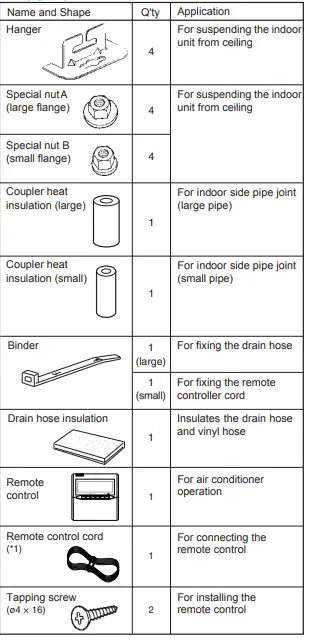
ACCESSORIES
INDOOR UNIT
OUTDOOR UNIT
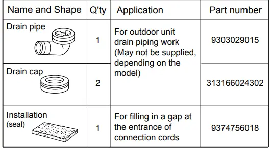
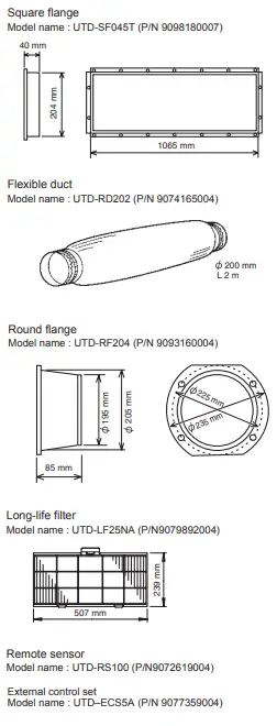
OPTIONAL PARTS