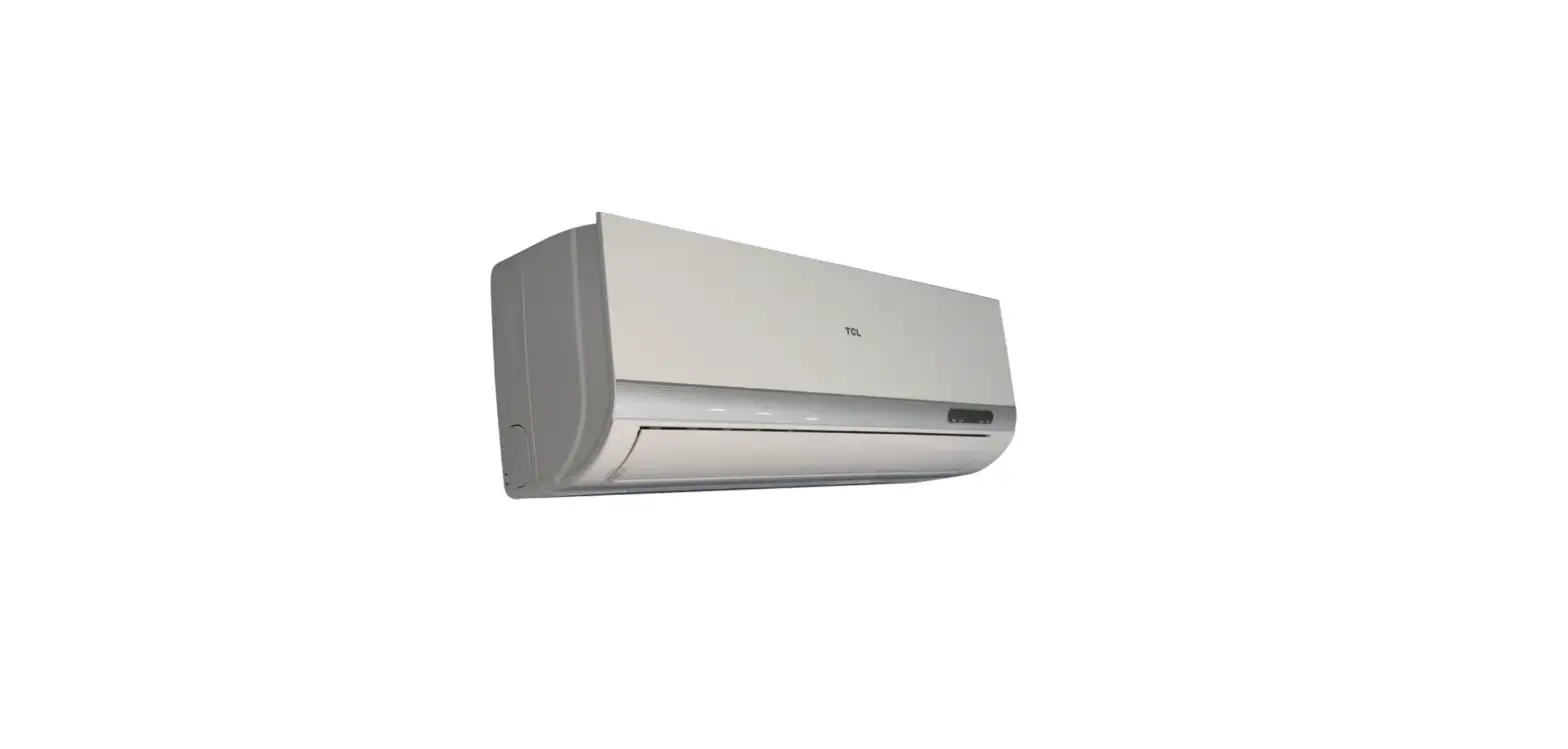
FUJITSU ASYA14LCC Split Type Room Air Conditioner Wall Mounted Type

Product Information
The Split Type Room Air Conditioner Wall Mounted Type comes in four different models: ASYA14LCC AOYR14LCC, ASYA14LCC AOYR14LCL, ASYA18LCC AOYR18LCC, and ASYA18LCC AOYR18LCL. The product has a cooling capacity ranging from 4.20 kW to 6.25 kW and a heating capacity ranging from 5.20 kW to 6.25 kW. It operates on a power source of 230V, 50Hz, and has a running current of 5.0 A to 7.7 A.
The indoor and outdoor units have different noise levels depending on the speed setting, with the indoor unit ranging from 25 dB to 48 dB and the outdoor unit ranging from 48 dB to 50 dB. The compressor is a hermetic type, 4 pole, 3 phase, DC inverter motor, rotary, and uses R410A refrigerant.
Product Usage Instructions
- Installation: Install the indoor unit and outdoor unit according to the instructions provided in the user manual.
- Power source: Connect the air conditioner to a power source of 230V and 50Hz.
- Operation: Use the remote control to turn the air conditioner on and off, adjust the temperature, and switch between cooling and heating modes. The air conditioner has four fan speed settings: high, middle, low, and quiet.
- Maintenance: Clean the air filters regularly to ensure optimal performance. Consult the user manual for detailed instructions.
- Troubleshooting: If you experience any issues with the air conditioner, refer to the troubleshooting section in the user
SPECIFICATIONS
ELECTRICAL DATA
| TYPE | Cooling & heating inverter | ||
| INDOOR UNIT | ASYA14LCC | ASYA18LCC | |
| OUTDOOR UNIT | AOYR14LC_ | AOYR18LC_ | |
| COOLING CAPACITY | 4.20 kW | 5.20 kW | |
| HEATING CAPACITY | 5.60 kW | 6.25 kW | |
| POWER SOURCE | 230 V | 230 V | |
| FREQUENCY | 50 Hz | 50 Hz | |
| RUNNING CURRENT | Cooling | 5.0 A | 7.6 A |
| Heating | 6.4 A | 7.7 A | |
| INPUT WATTS | Cooling | 1.11 kW | 1.72 kW |
| Heating | 1.45 kW | 1.73 kW | |
| E.E.R. Cooling | 3.78 kW/kW | 3.02 kW/kW | |
| COP Heating | 3.86 kW/kW | 3.61 kW/kW | |
| MOISTURE REMOVAL | 2.1 L/hr | 2.8 L/hr | |
| AIR CIRCULATION HIGH | Cooling | 700 m3/hr | 700 m3/hr |
| Heating | 700 m3/hr | 700 m3/hr | |
FAN MOTOR
| POWER SOURCE | 230 V | ||
| INDOOR UNIT ( cool / heat ) | High speed | 1,480 r.p.m. / 1,480 r.p.m. | |
| Middle speed | 1,260 r.p.m. / 1,300 r.p.m. | ||
| Low speed | 1,040 r.p.m. / 1,110 r.p.m. | ||
| Quiet | 850 r.p.m. / 950 r.p.m. | ||
| OUTDOOR UNIT ( cool / heat ) | 820 / 750 r.p.m. | 860 / 820 r.p.m. | |
NOISE LEVEL
| INDOOR UNIT ( cool / heat ) | High speed | 44 dB / 42 dB | |
| Middle speed | 38 dB / 37 dB | ||
| Low speed | 32 dB / 32 dB | ||
| Quiet | 25 dB / 27 dB | ||
| OUTDOOR UNIT ( cool / heat ) | 48 dB / 49 dB | 50 dB / 50 dB | |
COMPRESSOR AND REFRIGERANT
| TYPE | Hermetic type, 4 pole, 3 phase, DC inverter motor, Rotary | |
| DISCRIMINATION | DA130A1F-25F | |
| PRECHARGED REFRIGERANT | 1,150 g | |
| REFRIGERANT TYPE | R410A | |
| Pipe length FULL CHARGE | 15 m | 1,150 g |
| 20 m | 1,250 g | |
| ADDITIONAL CHARGE | 20 g/m | |
| MAXIMUM PIPE HEIGHT | 15 m | |
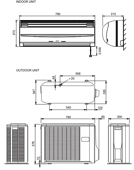
DIMENSIONS
| INDOOR UNIT H x W x D | 275 x 790 x 215 mm |
| OUTDOOR UNIT H x W x D | 578 x 790 x 300 mm |
WEIGHT
| INDOOR UNIT Gross / Net | 12 kg / 9 kg |
| OUTDOOR UNIT Gross / Net | 44 kg / 40 kg |
DIMENSIONS
(unit : mm)
REFRIGERANT SYSTEM DIAGRAM
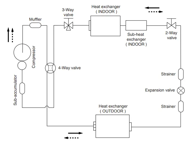

- Refrigerant pipe diameter
- Liquid : 1/4″ (6.35 mm)
- Gas : 1/2″ (12.7 mm)
CIRCUIT DIAGRAM
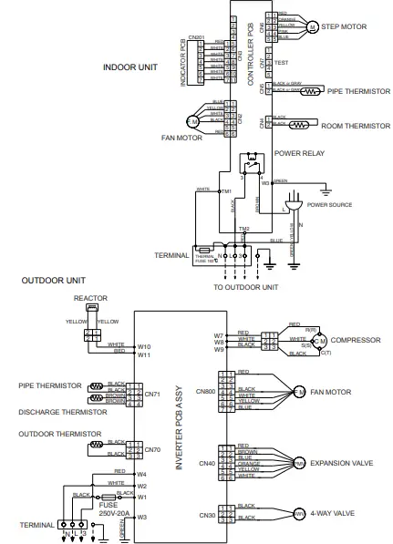
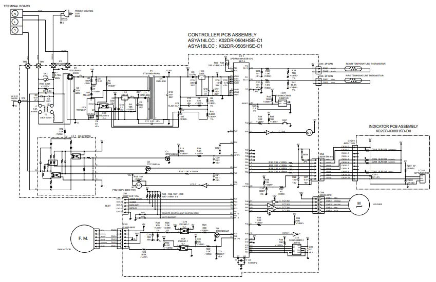
INDOOR PCB CIRCUIT DIAGRAM
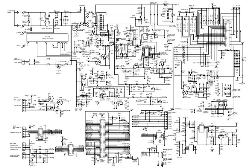
OUTDOOR PCB CIRCUIT DIAGRAM
INVERTER ASSEMBLY
- AOYR14LC_ : EZ-0055HUE
- AOYR18LC_ : EZ-005WHUE
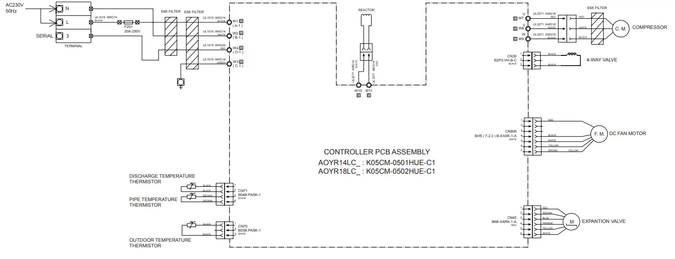
CONTROLLER PCB ASSEMBLY
- AOYR14LC_ : K05CM-0501HUE-C1
- AOYR18LC_ : K05CM-0502HUE-C1
ERROR CONTENTS
| Error | Display | Error | |
| Operation LED | Timer LED | ||
|
Serial signal error |
Normal | 2 flash | Serial signal (reverse) error, at operation start up |
| 3 flash | Serial signal (reverse) error, during oeration | ||
| 4 flash | Serial signal (forward) error, at operation start up | ||
| 5 flash | Serial signal (forward) error, during operation | ||
| Indoor unit thermistor error | 2 flash | 2 flash | Indoor temperature thermistor open / short |
| 3 flash | Heat exchanger middle thermistor open / short | ||
|
Outdoor unit thermistor error |
3 flash | 2 flash | Discharge thermistor open / short |
| 3 flash | Heat exchanger thermistor open | ||
| 4 flash | Outdoor temperature thermistor open / short | ||
|
Indoor unit control error |
4 flash | 2 flash | Forced automatic SW welded |
| 3 flash | Main relay welded | ||
| 4 flash | Power interruption error | ||
| 7 flash | VDD permanent stop protection | ||
| 8 flash | reverse VDD permanent stop protection | ||
|
Outdoor unit control error |
5 flash | 2 flash | Current trip error |
| 3 flash | CT abnormal | ||
| 5 flash | Compressor location detection error | ||
| 6 flash | Outdoor unit fan drive system abnormal | ||
| Indoor fan motor error | 6 flash | 2 flash | Abnormal lock |
| 3 flash | Abnormal rotation | ||
| Refrigerant cycle error | 7 flash | 2 flash | Discharge Temperature abnormal |
| 3 flash | Cooling high pressure abnormal rise | ||
| Optional function error | 8 flash | 4 flash | PFC circuit error |
| Model information error | 0.1 sec on/off | 0.1 sec on/off | Model information error |
OUTDOOR UNIT LED
| LED | ERROR |
| on | Discharge temperature abnormal |
| 0.5 second on / 0.5 second off | IPM overcurrent protection |
| 0.1 second on / 0.1 second off | Thermistor abnormal |
| 2.0 second on / 2.0 second off | CT abnormal |
| 0.1 second on / 2.0 second off | Compressor location abnormal |
| 5.0 second on / 5.0 second off | Fan abnormal |
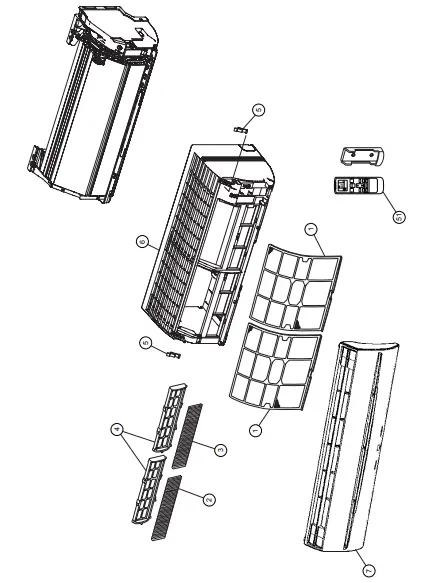
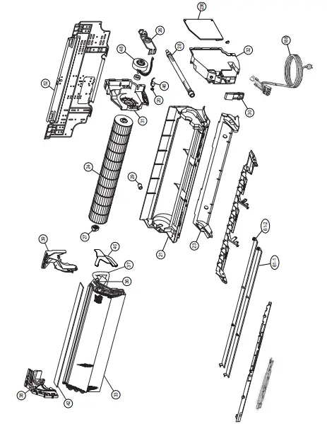
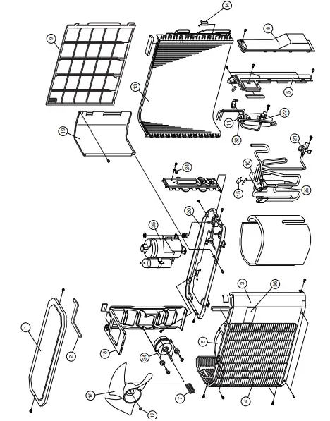
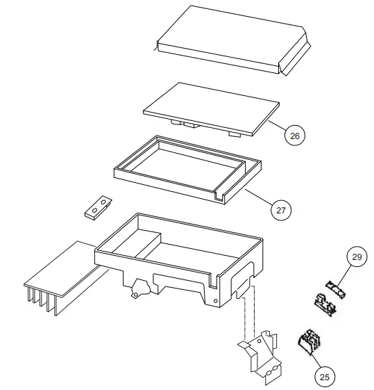
DISASSEMBLY ILLUSTRATION
INDOOR UNIT
OUTDOOR UNIT
PARTS LIST
INDOOR UNIT
| Ref. | Description | Part number | ||
| ASYA14LCC | ASYA18LCC | |||
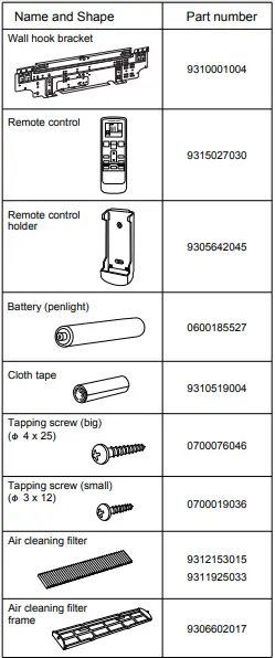
| 1 | Air Filter | 9309997011 | 9309997011 | |
| 2 | Filter (Electric) | 9312153015 | 9312153015 | |
| 3 | Filter (ION) | 9311925033 | 9311925033 | |
| 4 | Holder (Filter) | 9306602017 | 9306602017 | |
| 5 | Clamper (Grille) | 9306755010 | 9306755010 | |
| 6 | Front Panel Total Assy | 9313130169 | 9313130169 | |
| 7 | Intake Grille Assy | 9313131128 | 9313131128 | |
| 20 | Gear-A | 9309994003 | 9309994003 | |
| 21 | Casing Assy | 9311354079 | 9311354079 | |
| 23 | Cover (Casing)-B | 9314160011 | 9314160011 | |
| 24 | Crossflow Fan Assy | 9307836015 | 9307836015 | |
| 26 | Clamp (Motor) | 9310102008 | 9310102008 | |
| 27 | Shaft Holder-C Assy | 9306628017 | 9306628017 | |
| 28 | Drain Hose Assy | 9314147012 | 9314147012 | |
| 29 | Drain Cap Assy | 9314493010 | 9314493010 | |
| 30 | Wire Clamper | 9311946014 | 9311946014 | |
| 31 | Box (Switch) | 9312908011 | 9312908011 | |
| 32 | Cover (Switch) | 9312909018 | 9312909018 | |
| 33 | Evaporator Sub Assy | 9313791018 | 9313791018 | |
| 36 | Joint Pipe Assy | 9313792015 | 9313792015 | |
| 37 | Insulation (Pipe)-E | 9304607007 | 9304607007 | |
| 38 | Holder (Evaporator)-L | 9309982017 | 9309982017 | |
| 39 | Holder (Evaporator)-R | 9309983014 | 9309983014 | |
| 40 | Water Seal | 9312912018 | 9312912018 | |
| 42 | Air Seal | 9310611005 | 9310611005 | |
| 46 | Step Motor | 9900139025 | 9900139025 | |
| 48 | Fan Motor Assy | 9601814016 | 9601814016 | |
| 51 | Remote Control Unit | 9315027030 | 9315027030 | |
| 52 | Bracket Panel | 9310001004 | 9310001004 | |
| 61-1 | Flow Control Panel-U | 9309991033 | 9309991033 | |
| 61-2 | Flow Control Panel-Z | 9309992030 | 9309992030 | |
| 188 | Power Cord Assy | 9900339012 | 9900339012 | |
| 236 | Controller PCB Assy | 9705656116 | 9705656123 | |
| (K02DR-0504HSE-C1) | (K02DR-0505HSE-C1) | |||
| — | Pipe Thermistor | 9702039042 | 9702039042 | |
| — | Room Thermistor | 9700801108 | 9700801108 | |
| — | Indicator PCB Assy | 9705039032 | 9705039032 | |
| — | Evaporator B Assy | 9311275022 | 9311275022 | |
OUTDOOR UNIT
| Ref. | Description | Part number | ||
| AOYR14LC_ | AOYR18LC_ | |||
| 1 | Top Panel Assy | 9309230057 | 9309230057 | |
| 2 | Top Panel Seal | 9309228016 | 9309228016 | |
| 3 | Cabinet Assy | 9314809040 | 9314809040 | |
| 4 | Blow Down Grille | 9308884015 | 9308884015 | |
| 5 | Cabinet Right Assy | 9309236011 | 9309236011 | |
| 6 | Fan Ring | 9308885012 | 9308885012 | |
| 7 | Grip | 9308880017 | 9308880017 | |
| 8 | Switch Cover | 9308882028 | 9308882028 | |
| 9 | Protective Net | 9315319012 | 9315319012 | |
| 10 | 4-Way Valve Assy | 9315726018 | 9315726018 | |
| 11 | Pulse Motor Valve Assy | 9311641018 | 9311641018 | |
| 13 | Condenser Assy | 9311382027 | 9311382027 | |
| 14 | Thermistor Spring-A | 313728262708 | 313728262708 | |
| 15 | Thermistor Spring | 9300089012 | 9300089012 | |
| 16 | Propeller Fan | 9309909014 | 9309909014 | |
| 17 | Nut | 9304902003 | 9304902003 | |
| 18 | Motor Bracket | 9308872012 | 9308872012 | |
| 19 | Separator Assy | 9312971015 | 9312971015 | |
| 20 | Base Assy | 9308869081 | 9308869081 | |
| 21 | 3-Way Valve Assy | 9315159014 | 9315159014 | |
| 22 | 2-Way Valve Assy | 9313064013 | 9313064013 | |
| 24 | Cord Clamp | 9307271014 | 9307271014 | |
| 25 | Terminal | 9306489038 | 9306489038 | |
| 26 | Inverter PCB Assy | 9707039023 | 9707039030 | |
| 27 | PCB Holder | 9313074029 | 9313074029 | |
| 29 | Fuse | 0600382018 | 0600382018 | |
| 32 | Expansion Valve Coil | 9900057039 | 9900057039 | |
| 34 | Fan Motor | 9601725015 | 9601725015 | |
| 35 | Compressor Assy | 9313764012 | 9313764012 | |
| 36 | Emblem | 9315210012 | 9315210012 | |
| 39 | Solenoid Coil | 9970033018 | 9970033018 | |
| — | IPM | 9705720015 | 9705720015 | |
| — | Thermistor Assy | 9900148027 | 9900148027 | |
| — | Outdoor Thermistor | 9900210045 | 9900210045 | |
| — | Strainer A | 9313197018 | 9313197018 | |
| — | Strainer C | 9311440017 | 9311440017 | |
| — | Condenser Total Assy | 9311381037 | 9311381037 | |
ACCESSORIES