HARVEST TEC 600J Moisture Monitoring System
 Introduction
 Introduction
Thank you for purchasing a Harvest Tec Model 600J Moisture Monitoring System. This 600J system has been designed to plug directly into the baler’s ISOBUS and/or an Apple iPad (not included) display. The 600J Moisture Monitoring System offers these advantages:
- Operation coordinated with baler operation
- Less cab clutter provides better visibility
- Ease of use with all information on one monitor
- Records kept together
- The system is ready for future updates
The 600J Moisture Monitoring kit includes the following parts: Dual Channel Processor (DCP), Moisture Sensors, Harnesses, and Miscellaneous Hardware. For your convenience, a parts breakdown for the 600J Moisture Monitoring System is included in the back of this manual. Your local dealer can assist you in answering any questions and ordering parts. Right, and Left sides are determined by facing in the direction of forwarding travel.
System Requirements
- Made for iPad® (3rd through Pro 2nd generation), running the current iOS operating system or one version previous required for iPad option
- iPad is a trademark of Apple Inc., registered in the U.S. and other countries.
- 600 Series Applicators with serial numbers before DCP27000 will require the DCP to be sent to Harvest Tec for a required update in order to use the iPad Integration Module (030-6672C).
- Hay App version must be at least 2.5.18 (or higher) to operate with the iPad Integration Module
- If choosing to operate the unit through the ISOBUS monitor, part number 006-6670A will need to be ordered through your local equipment dealer.
Tools Needed
- Standard wrench set
- Electric drill and bits
- Side cutter
- Crescent wrench
- Standard screwdriver
- The standard nut driver set
- Standard socket set
- Hammer
- Metal cutting tools
- Hose cutter
- Center punch
Installation of Dual Channel Processor (DCP)
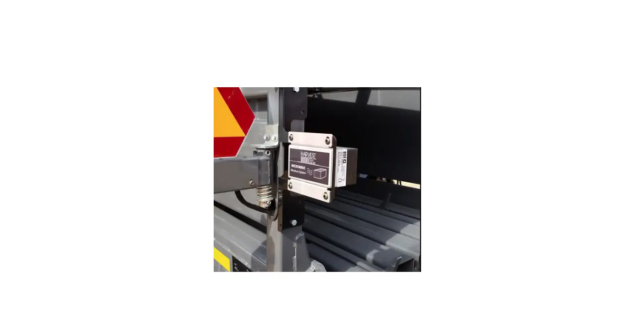
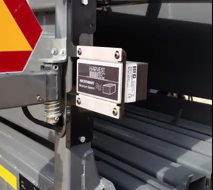
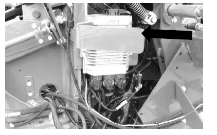
To mount the Dual Channel Processor (DCP) onto your John Deere L330 / L340 baler, the DCP location will be on the back of the right twine box. The location will vary slightly depending on the placement of safety decals from the factory, do not cover the safety decals. Mount DCP on the back of the right-hand twine box using Figure 1 as a reference. DCP location is recommended 5” (12.5cm) from the inside edge and 5” (12.5cm) from the top of the twine box.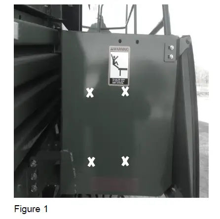
Installation of End of Bale Sensor 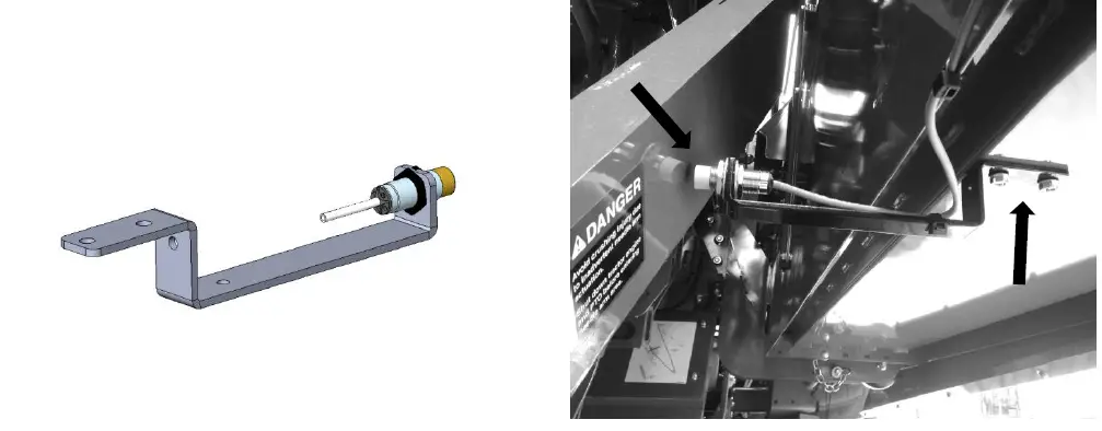
Mount the end of bale sensor bracket (001-4648J) as shown. Under the twine box mark and drill two 3/8” holes and attach the bracket using two 5/16” x 1” self-tapping screws, and 5/16” flange nuts. Position the bolts so the bolt heads are inside the twine box so they don’t interfere with the twine. Mount the sensor in hole location centered alongside the needle arm, keep the sensor 1/4″ (7mm) from the needle arm and tighten both nuts. Route the sensor wire along the bottom side of the twine box toward the twine box pivot point. Secure the wire to the twine box and around the pivot point to avoid damage to the wire. Once routed around the pivot point, connect the EOB sensor wire to the Dual Channel Processor (DCP).
Installation of Star Wheel Moisture Sensors
Star Wheel Mounting – remove any material from the bale chute. The star wheels are to be mounted on the transition bracket on both sides of the bale chute located after knotters shown above. Holes have been installed at the factory, however you need to remove the bracket and cut 3/4” (19mm) off the bracket as indicated below to allow proper spacing for star wheel assembly. Once complete, touch up with spray paint to prevent rusting and place the carriage bolts that mount the transition bracket back in original bracket mounting holes (A) before mounting star wheel assembly (C). Insert the 5/16” by 3 1/4” Allen head bolts up through the transition bracket and use nuts to hold the bolts in place (B). Place the star wheel block over the nuts. Place twine guard on top of star wheel (D), the guard containing bale rate sensors will be placed on the right side. Note: Thicker part of star wheel block should be on baler side.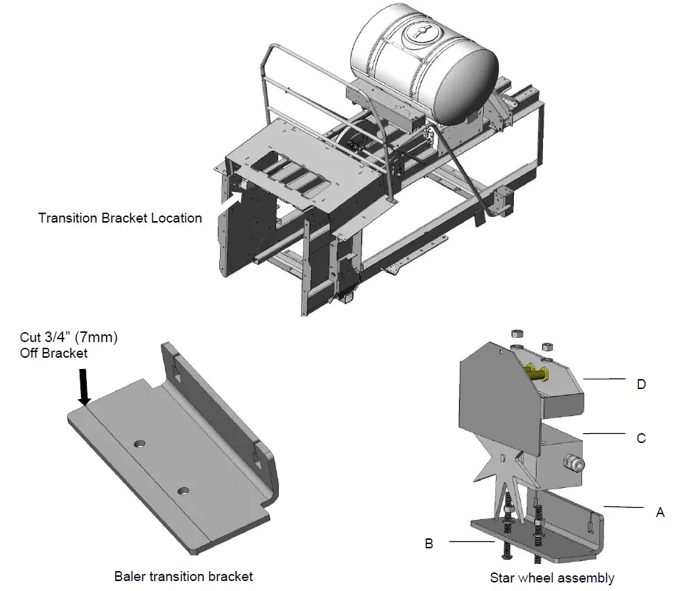
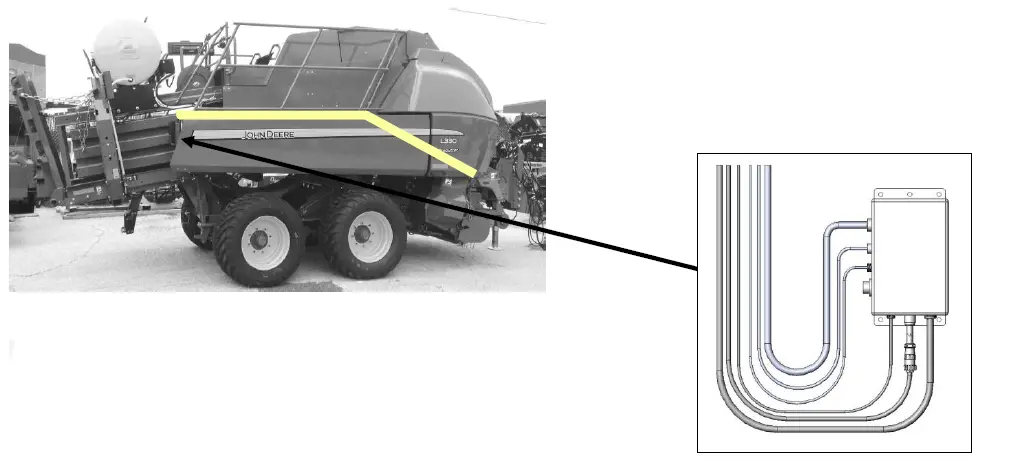
John Deere L330 / L340 Balers Harness Routing and ISOBUS Connection
- Main wiring harness and power cord connection to baler harness terminator connection

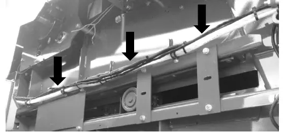
Route cords 006-6650LS2 along this path. Keep cords away from moving parts and hydraulic hoses. Secure with existing cable clamps or use cable ties. When all connections are made to DCP secure wires as shown below. - Route for mounting harness and hoses from DCP and Pumps

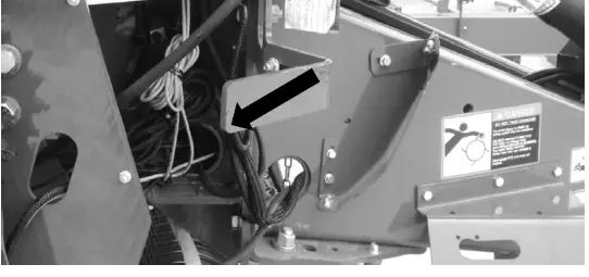
- Route ISO Integration Harness (006-6650VAJ) to opposite side of baler through support cylinder.

- ISOBUS Connection
Locate harness 006-6650VAJ and connect to baler interface harness next to baler’s processor (below) on front left side of baler. Remove baler terminating resistor and connect to short pigtail on 006-6650VAJ Harness.
Installation of iPad Integration Control
Locate a safe location in the cab of the tractor to place the iPad Integration Control (030-6672C). Recommended location is securely fastened out of the operators way in a location that is close enough to reach with the iPad cord.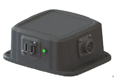
Connect the Power / Communication harness (006-6650TM(E)) to the bottom of the receiver.
To operate the applicator, plug the iPad cord into the communication port indicated by: 
iPad Integration Control Light Signals
Green Slow Blink – Power supplied to the applicator system and the unit is going through its startup process. This will take approximately 25-35 seconds.
Green Double Blink – Indicating the iPad module recognizes the iPad but the app is not open or connected. Green Solid Light – Module is connected to the app and is ready to operate.
*Recommended to use the USB cable included with the applicator kit (006-6672USBC)
Bluetooth Receiver Lights
Pre-2020 applcaitors equipped with Bluetooth receivers (030-6672B) are now equipped with lights to indicate both power and Hay App connection on the Apple iPad. Clean light regularly
Blinking Lights – System is waiting for the processor to connect, which could take up to 35 seconds.
Red Light – The Bluetooth receiver has power
Green Light – The Bluetooth receiver is connected to the Hay App. 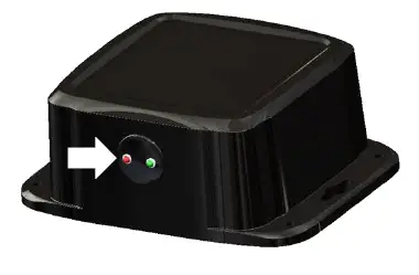
600 Series Applicators with serial number before DCP27000 will require the DCP to be sent to Harvest Tec for a required update in order to use the iPad Integration Module (030-6672C). Hay App version must be at least 2.5.18 (or higher) to operate with the iPad Integration Module
Made for Apple iPad badge
Use of the Made for Apple iPad badge means that an accessory has been designed to connect specifically to the Apple product(s) identified in the badge and has been certified by the developer to meet Apple performance standards. Apple is not responsible for the operation of this device or its compliance with safety and regulatory standards.
Please note that the use of this accessory with an Apple product may affect wireless performance.
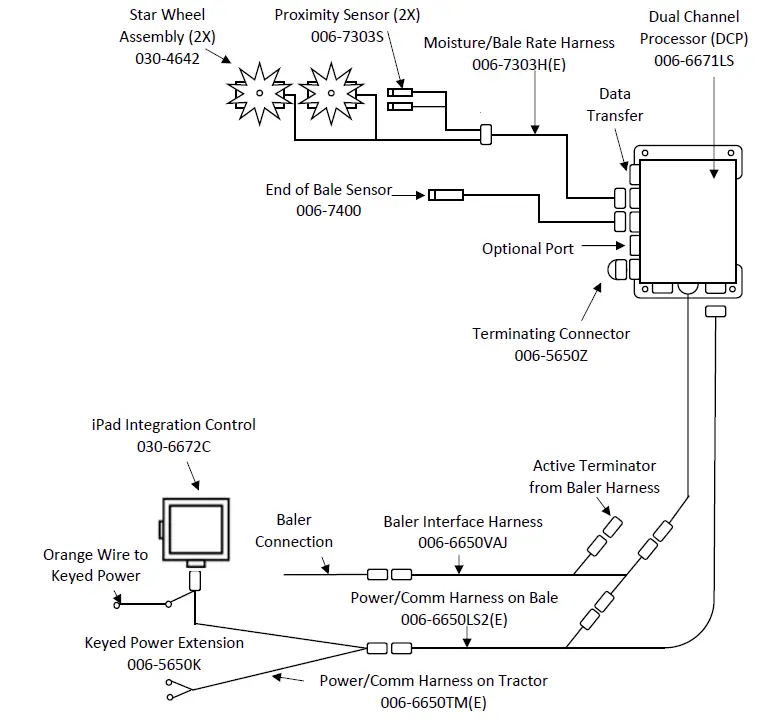
John Deere L330 / L340 Balers Harness/Wiring Installation for using ISOBUS Display
- The Baler Power/Communication Harness (006-6650LS2(E)) will attach to the open port of the Tractor Harness (006-6650TM(E)) and run back to the Dual Channel Processor (DCP 006-6671LS).
- Connect the large plug of the Baler Power/Communication Harness (006-6650LS2(E)) to the bottom
(shorter side) of the DCP. - Attach the Baler Interface Harness (006-6650VAJ) in between the short whip cable hardwired to the DCP and the main Power/Communication Harness. Make sure Active Terminator removed from the baler processor is attached to the Baler Interface Harness (006-6650VAJ).
- Connect the iPad Integration Control (030-6672C) to Communication Harness (006-6650TM(E)).
- Install the Terminating Connector (006-5650Z) to the port labeled Modular Port on the Pump Controller (006-5672).
- Attach moisture and bale rate harness (006-7303H(E)) to the DCP (006-6671LS).
- Connect Keyed Power Extension harness (006-5650K) to a keyed power source.
- Note: the Optional Port and the Data Transfer Port are not used in this application.

Pin Outs
Power/Comm Harness 006-6650TM(E) at Hitch 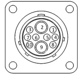
| Pin 1 | Red | +12V Power to TSD |
| Pin 2 | Red | +12V Power to DCP |
| Pin 3 | Orange | Keyed Power |
| Pin 4 | Gray | Shield |
| Pin 5 | Green | HT Can Low |
| Pin 6 | Yellow | HT Can Hi |
| Pin 7 | Orange | Can1 Hi |
| Pin 8 | Black | Ground from TSD |
| Pin 9 | Black | Ground from DCP |
| Pin 10 | Blue | Can1 Low |
Power/Comm Harness 006-6650LS2(E) at Hitch 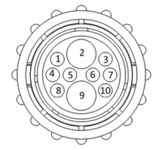
| Pin 1 | Red | +12V Power to TSD |
| Pin 2 | Red | +12V Power to DCP |
| Pin 3 | Orange | Keyed Power |
| Pin 4 | Gray | Shield |
| Pin 5 | Green | HT Can Low |
| Pin 6 | Yellow | HT Can Hi |
| Pin 7 | Orange | Can1 Hi |
| Pin 8 | Black | Ground from TSD |
| Pin 9 | Black | Ground from DCP |
| Pin 10 | Blue | Can1 Low |
iPad Integration Control / BLE on Harness 006-6650TM(E) 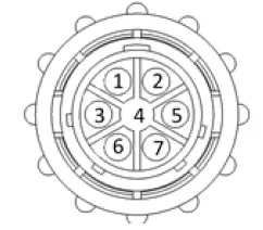
| Pin 1 | Red | +12V Power from DCP |
| Pin 2 | Black | Ground from TSD |
| Pin 3 | Yellow | HT Can Low |
| Pin 4 | Gray | Shield |
| Pin 5 | Green | HT Can Hi |
| Pin 6 | Orange | Can1 Hi |
| Pin 7 | Blue | Can1 Low |
ISOBUS Plug Baler Side 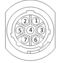
| Pin 1 | N/A | |
| Pin 2 | N/A | |
| Pin 3 | 120 OHM with Pin 5 | |
| Pin 4 | N/A | |
| Pin 5 | 120 OHM with Pin 3 | |
| Pin 6 | Orange | Can1 Hi |
| Pin 7 | Blue | Can1 Low |
ISOBUS Plug Tractor Side 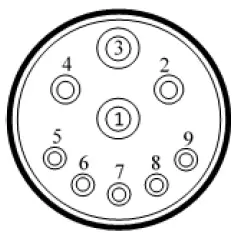
| Pin 1 | N/A | |
| Pin 2 | N/A | |
| Pin 3 | +12V Keyed Tractor Power | |
| Pin 4 | N/A | |
| Pin 5 | N/A | |
| Pin 6 | N/A | |
| Pin 7 | N/A | |
| Pin 8 | Orange | Can1 Hi |
| Pin 9 | Blue | Can1 Low |
Main Power Connector on DCP 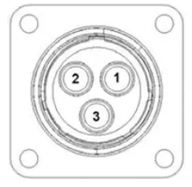
Pin 1 Red +12V Power from tractor
Pin 2 Black Ground from tractor
Pin 3 Orange Keyed power
Star Wheel and Bale Rate Sensor connector on DCP 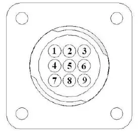
| Pin 1 | Blue | +12V Power |
| Pin 2 | Orange | Ground |
| Pin 3 | Black | Signal for sensor 1 |
| Pin 4 | White | Signal for sensor 2 |
| Pin 5 | N/A | |
| Pin 6 | N/A | |
| Pin 7 | N/A | |
| Pin 8 | Violet | Star wheel input 1 |
| Pin 9 | Brown | Star wheel input 2 |
End of Bale sensor on DCP 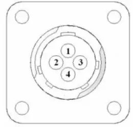
Pin 1 Brown Sensor Power
Pin 2 Blue Sensor Ground
Pin 3 N/A
Pin 4 Black Signal from Sensor
Pump Communication Plug on DCP
| Pin 1 | Red | +12V Can |
| Pin 2 | Red | +12V Power |
| Pin 3 | Gray | Shield |
| Pin 4 | Green | Comm Channel OH |
| Pin 5 | Yellow | Comm Channel OL |
| Pin 6 | Blue | Comm Channel IH |
| Pin 7 | Orange | Comm Channel IL |
| Pin 8 | Black | Can Ground |
| Pin 9 | Black | Power Ground |
| Pin 10 | N/A |
Pump Connection Colors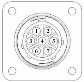
| Pin 1 | Black with Orange Stripe | Pump 1 Ground |
| Pin 2 | Black with Green Stripe | Pump 2 Ground |
| Pin 3 | Black with Yellow Stripe | Pump 3 Ground |
| Pin 4 | N/A | |
| Pin 5 | Orange with Black Stripe | Pump 1 Positive |
| Pin 6 | Green with Black Stripe | Pump 2 Positive |
| Pin 7 | Yellow with Black Stripe | Pump 3 Positive |
Flow Meter Connection on Pump Controller
Pin 1 White 5 – 12V (+) Supply
Pin 2 Green Ground
Pin 3 Brown Signal
Pin 4 Black Shield
Connector for Crop Eyes on DCP 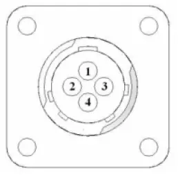
Pin 1 Red +12V Power
Pin 2 Black Ground
Pin 3 White Signal
Pin 4 N/A
006-6650VAJ Harness to Baler Plug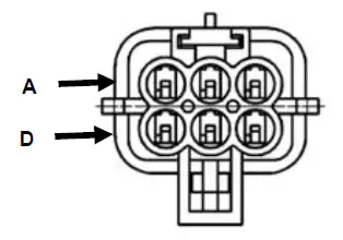
Pin A N/A
Pin B Red TBC Power
Pin C N/A
Pin D Gray TBC Ground
Pin E Orange Can1 Hi
Pin F Blue Can1 Low
Troubleshooting
| PROBLEM | POSSIBLE CAUSE | SOLUTION |
| Moisture reading errors (high or low) | 1. Wire disconnected or bad connection between star wheels and DCP | 1. Reconnect wire. |
| 2. Low power supply to DCP | 2. Check voltage at box. (Min of 12 volts required.) See Diagnostics section of manual. | |
| 3. Dry hay lower than 8% moisture or wet hay over 75%. | 3. System reads 8-70% moisture. | |
| 4. Ground contact with one or both star wheels and baler mounted processor. | 4. Reconnect. | |
| 5. Short in wire between star wheels and DCP. | 5. Replace wire. | |
| 6. Check hay with hand tester to verify. | 6. Contact Harvest Tec if conditions persist. | |
| Moisture readings erratic. | 1. Test bales with hand tester to verify that DCP has more variation than hand tester. | |
| 2. Check all wiring connections for corrosion or poor contact. | 2. Apply dielectric grease to all connections. | |
| 3. Check power supply at tractor. Voltage should be constant between 12 and 14 volts. | 3. Install voltage surge protection on tractors alternator. | |
| Terminal reads under or over power. | 1. Verify with multi-meter actual voltage. Voltage range should be between 12-14 volts. | 1. Clean connections and make sure applicator is hooked to battery. See Diagnostics section of manual. |
| Bale rate displays zero. | 1. Bale rate sensors are reversed. 2. Short in cable. 3. Damaged sensor. 4. Sensor too far from starwheel. | 1. Switch the sensors next to the star wheel. 2. Replace cable. 3. Replace sensor. 4. Adjust gap between prox sensor and star wheel so it is 1/8-1/4” away. |
| Bluetooth Receiver lights will not illuminate | 1. Bluetooth receiver not connected 2. Harness disconnected 3. Low power | 1. Check connections and voltage. Minimum 12.5V needed. |
| Blinking Lights – System is waiting for the processor to connect, which could take up to 35 seconds. Red Light – The Bluetooth receiver has power Green Light – When the proper active connection is selected in the Hay App menu, the green light will indicate connection with the iPad. | ||
600J Series Control and Harnesses Dual Channel Processor (DCP) 
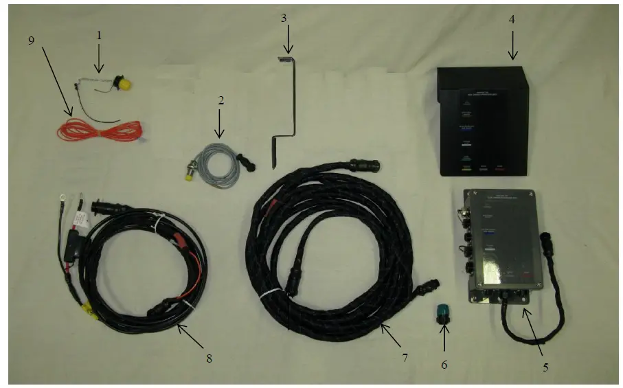
| Ref | Description | Part Number | Qty |
| 1 | Dust Plugs | 006-5651PLUGS | 1 |
| 2 | End of Bale Sensor 600 Series | 006-7400 | 1 |
| 3 | End of Bale Sensor Bracket | 001-4648J | 1 |
| 4 | DCP Shield Cover | 001-5650X | 1 |
| 5 | DCP Main Control LS 600 AUTO | 006-6671LS | 1 |
| 6 | Terminating Connector (Green Cap) | 006-5650Z | 1 |
| 7 | DCP Baler Harness 30 Ft | 006-6650LS2(E) | 1 |
| 8 | DCP Tractor Harness | 006-6650TM(E) | 1 |
| 9 | Key Switch Wire | 006-5650K | 1 |
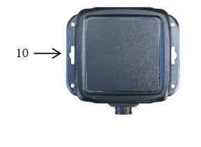
| 10 | iPad Integration Control | 030-6672C | 1 |
| NP | Baler Integration Harness | 006-6650VAJ | 1 |
| NP | USB Cord | 006-6672USBC | 1 |
 Star Wheel Moisture Sensors and Bale Rate Sensors
 Star Wheel Moisture Sensors and Bale Rate Sensors
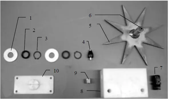
| Ref | Description | Part# | Qty | Ref | Description | Part# | Qty |
| 1 | Washer (per side) | 006-4642K | 2 | 8 | Star wheel block | 006-4641D | 2 |
| 2 | Dust seal (per side) | w/006-4642K | 1 | 9 | Plug fitting | 003-F38 | 2 |
| 3 | Snap ring (per side) | w/006-4642K | 2 | 10 | Block Cover | 006-4641B | 2 |
| 4 | Swivel | 006-4642A | 2 | 1-10 | Star wheel assembly | 030-4642 | 2 |
| 5 | Star wheel | 030-4641E | 2 | NP | Twine guard – right (prox) | 001-4644H | 1 |
| 6 | Insert | w/ Ref # 5 | 2 | NP | Twine guard – left | 001-4645H | 1 |
| 7 | Wiring grommet | 008-0821A | 2 |
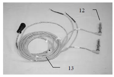
| Ref | Description | Part# | Qty |
| 12 | Bale rate sensor | 006-7303S | 2 |
| 13 | Moisture and bale rate harness | 006-7303H(E) | 1 |
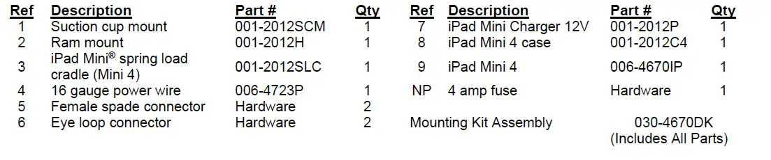
Optional iPad Mini Mounting Kit (030-2014MK) 
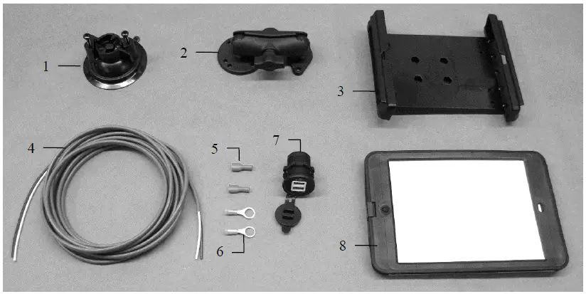
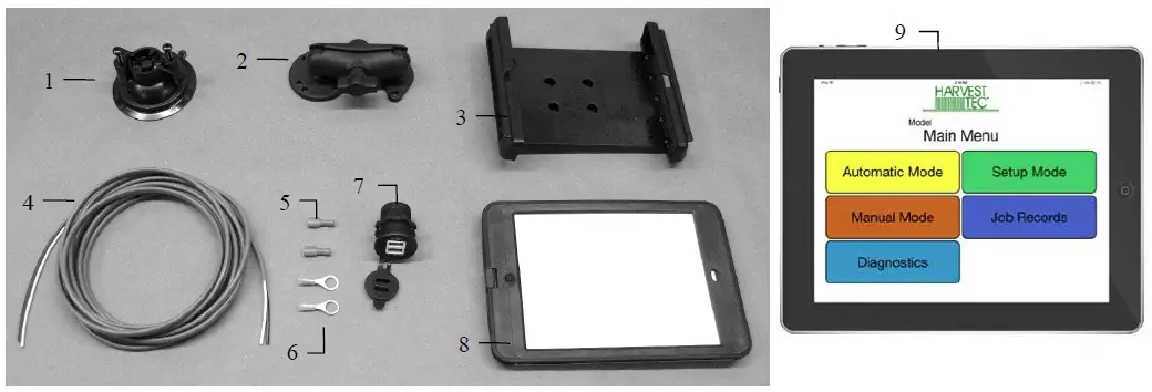
| Ref | Description | Part # | Qty |
| 1 | Suction cup mount | 001-2012SCM | 1 |
| 2 | Ram mount | 001-2012H | 1 |
| 3 | iPad Mini® spring load cradle (Mini 4) | 001-2012SLC | 1 |
| 4 | 16 gauge power wire | 006-4723P | 1 |
| 5 | Female spade connector | Hardware | 2 |
| 6 | Eye loop connector | Hardware | 2 |
| 7 | iPad Mini Charger 12V | 001-2012P | 1 |
| 8 | iPad Mini 4 case | 001-2012C4 | 1 |
| NP | 4 amp fuse | Hardware | 1 |
| Mounting Kit Assembly | 030-2014MK | ||
| (Includes All Parts) | |||
Installation Instructions
- Identify 12V power source for wires to connect.
- Eye loops included if wiring directly to the battery is desired.
- Test for key power source if preferred to have power to the USB shut off with the key.
- Once power source is identified, cut wires to desired length.
- Crimp the two supplied quick connectors onto each the white and black wire.
- Remove the round locking plastic nut from USB plug before connecting the wires. Black (+) White (-).
- The wires will then be hooked to the designated terminals on the bottom of the USB plug
- Drill a 1 1/8” hole in the preferred mounting location. Be sure to clean any sharp edges after drilling.
- Feed the wires through the mounting hole.
- If using the round plastic nut to secure plug in place, slide the nut back over the wiring before connecting the wires to powered source.
- Connect the wires to the identified power source if easier to do so before tightening the plug into place.
- Tighten plug using either the round plastic nut or mounting plate and two screws, both options supplied.
- Once connected, hook a USB charging cord into the plug and connect a mobile device/tablet to ensure the plug is operating as you wish (key power working properly if necessary).
NOTE: This plug is not designed to charge two iPads. System damage could occur if this is attempted. System will charge a mobile phone and iPad simultaneously without problem. iPad mini is a trademark of Apple Inc., registered in the U.S. and other countries.
Optional iPad Display Kit (030-4670DK) 
Installation Instructions
- Identify 12V power source for wires to connect.
- Eye loops are included if wiring directly to the battery is desired.
- Test for key power source if preferred to have power to the USB shut off with the key.
- Once power source is identified, cut wires to desired length.
- Crimp the two supplied quick connectors onto the white and black wire.
- Remove the round locking plastic nut from USB plug before connecting the wires. Black (+) White (-).
- The wires will then be hooked to the designated terminals on the bottom of the USB plug
- Drill a 1 1/8” hole in the preferred mounting location. Be sure to clean any sharp edges after drilling.
- Feed the wires through the mounting hole.
- If using the round plastic nut to secure plug in place, slide the nut back over the wiring before connecting the wires to powered source.
- Connect the wires to the identified power source if easier to do so before tightening the plug into place.
- Tighten plug using either the round plastic nut or mounting plate and two screws, both options supplied.
- Once connected, hook a USB charging cord into the plug and connect a mobile device/tablet to ensure the plug is operating as you wish (key power working properly if necessary).
NOTE: This plug is not designed to charge two iPads. System damage could occur if this is attempted. System will charge a mobile phone and iPad simultaneously without a problem.
Harvest Tec LLC. Warranty and Liability Agreement
Harvest Tec, LLC. will repair or replace components that are found to be defective within 12 months from the date of manufacture. Under no circumstances does this warranty cover any components which in the opinion of Harvest Tec, LLC. have been subjected to negligent use, misuse, alteration, accident, or if repairs have been made with parts other than those manufactured and obtainable from Harvest Tec, LLC. Our obligation under this warranty is limited to repairing or replacing free of charge to the original purchaser any part that in our judgment shows evidence of defective or improper workmanship, provided the part is returned to Harvest Tec, LLC. within 30 days of the failure. If it is determined that a non-Harvest Tec branded hay preservative has been used inside the Harvest Tec applicator system where the failure occurred, then Harvest Tec reserves the right to deny the warranty request at their discretion. Parts must be returned through the selling dealer and distributor, and transportation charges prepaid. This warranty shall not be interpreted to render Harvest Tec, LLC. liable for injury or damages of any kind, direct, consequential, or contingent, to persons or property. Furthermore, this warranty does not extend to loss of crop, losses caused by delays or any expense prospective profits or for any other reason. Harvest Tec, LLC. shall not be liable for any recovery greater in amount than the cost or repair of defects in workmanship. There are no warranties, either expressed or implied, of merchantability or fitness for a particular purpose intended or fitness for any other reason. This warranty cannot guarantee that existing conditions beyond the control of Harvest Tec, LLC. will not affect our ability to obtain materials or manufacture necessary replacement parts. Harvest Tec, LLC. reserves the right to make design changes, improve design, or change specifications, at any time without any contingent obligation to purchasers of machines and parts previously sold
HARVEST TEC, LLC.
P.O. BOX 63
2821 HARVEY STREET
HUDSON, WI 54016
PHONE: 715-386-9100
1-800-635-7468
FAX: 715-381-1792
Email: [email protected]


