HARVEST TEC 201SS Small Square Baler Precision Moisture Sensing Kit Owner’s Manual
Introduction
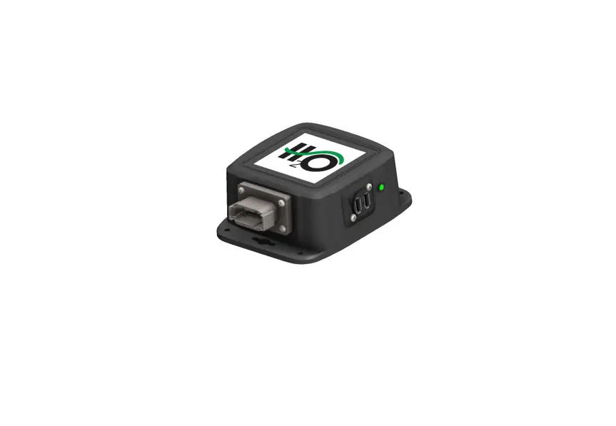
Congratulations and thank you for purchasing a Harvest Tec H2O Moisture Sensing Kit Model 201SB system.
Please read this manual carefully to ensure correct steps are taken to attach the system to the baler. This system is designed to read moisture at levels of 5-33%.
Requirements
The app will support operation of the current operating system and one previous version for both Apple and Android devices.
It is recommended for proper communication that the original phone/tablet power cable is used. Many lower cost power cables do not meet requirements to properly charge and communicate to the Harvest Tec H2O module.
Tools Needed
SAE wrench set Hammer Drill bit set
Standard screw driver Measuring tape Center punch
Side cutter SAE socket set
Installation of Star Wheels
Two-Tie Balers Only
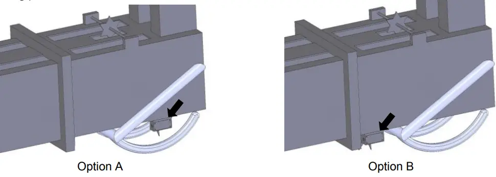
The pair of star wheels will need to mount on the bottom side as close to the front of the bale chute as possible and at least 3/8” (10mm) away from any metal. They will need to maintain a safe distance away from the twine.
Depending on the baler model the star wheels can mount in front of the needle arm Option A (below) if there is space available. When there is not enough room for the star wheel use Option B
The star wheels will require two holes to be drilled per block, when drilling make sure to keep the wheel square to the bale chamber. Any angle will cause stress on the wheel and will eventually cause the wheel to work itself out of the block. Some balers may require a notch cut on the bottom of the bale chamber to mount the star wheels as close to the front of the chamber as possible.
Use the supplied bolts and place the head inside of the bale chamber. Next attach 001-6707ES to the outside of the chamber. Then attach the star wheels to the bolts followed by the flat washer, lock washer, and nut.
First, remove the cover from the star wheel block and use a 1/4” (7mm) nut driver to remove the nut from the electronic swivel. Next, run the star wheel sensor wire through the black grommet and place the eye terminal on the star wheel sensor. Tighten the eye loop with the nut on the sensor and put the star wheel cover back on the base. Next, tighten the grommet to form a tight seal around the wire. Secure the harness to the baler to avoid moving parts.
Three-Tie Balers Only
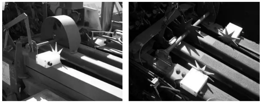
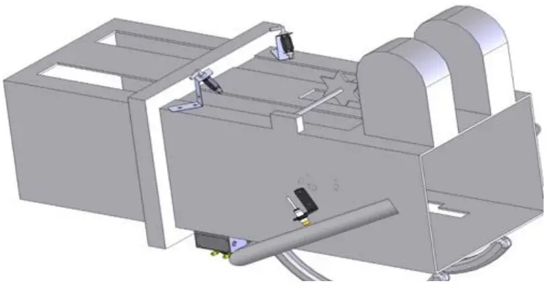
When using a three-tie baler the star wheels will need to be mounted on the top of the bale chamber as close to the knotters as possible (shown below). Use the instructions above for proper star wheel installation.
Control Box Installation
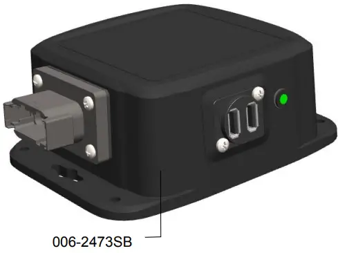
Locate a safe location in the cab of the tractor to place the control box (006-2473SB). Recommended location is as close to the tablet or phone being used to control the system.
Connect the Power Harness (006-2470P) and the Baler Power Communication Harness (006-2470SS).
The control box (006-2473SB) is equipped with a green light to indicated both power and connection.
Plug the tablet/phone cord into the communication port (closest to light) and indicated by:
Slow Blink – System has power but not connected to phone or tablet.
Solid Green – Device is connected.
**It is recommended for proper communication that the original phone/tablet power cable is used. Many lower cost power cables do not meet requirements to properly charge and communicate to the Harvest Tec H2O module.
End of Bale Sensor Installation – 200FCA (Optional)
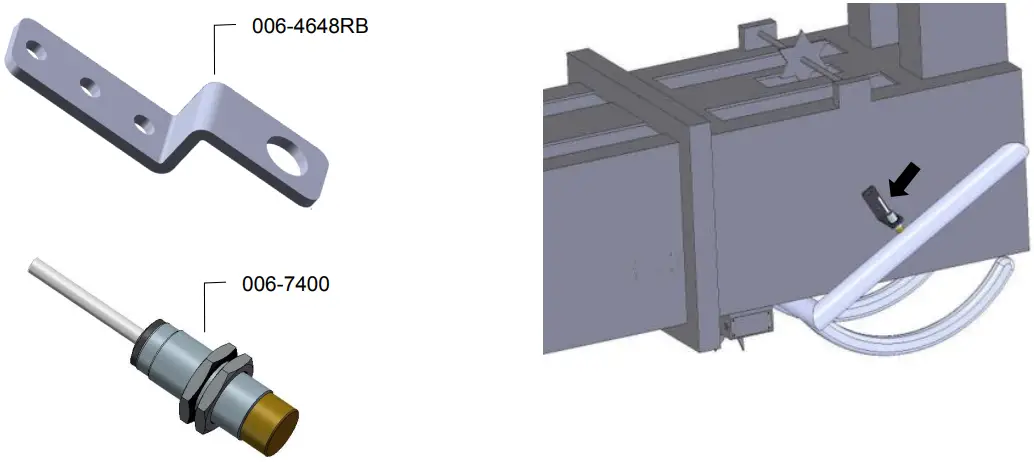
The end of bale sensor is used to determine when the baler needle arm moves. With this information the system is able to show the average moisture of the previous bale. Part number for kit is 200FCA
Mount the 006-7400 sensor to the mounting bracket 001-4648RB as shown below. Mount the assembly on the right side of the baler chamber. The face of the sensor needs to be parallel to the arm attached to the needles.
Note: The bracket may need to be slightly bent for the proper positioning. Mark and drill two 3/8” (10mm) holes. Install the sensor using two 5/16” x 1“ allen head bolts, locks, and nuts.
The end of the sensor needs to be no greater than 1/4” (7mm) away from the needle arm. Tighten nuts on sensor after adjustment.
The harness will need to be routed toward the harness at the tongue of the baler. Secure with cable ties and take care to avoid pinch points. The harness extension (006-7400EXT) may need to be used.
Dye Marker Installation – 200DM (Optional)
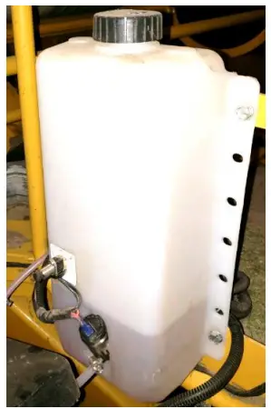
Locate the dye marking kit tank and pump assembly (005-9015). Identify a suitable mounting location for the tank away from moving parts and hydraulic lines on the baler. Be sure to mount the tank within 10’ of the connection on the Baler Pwr/Comm Harness (006-2470SS), wiring details in the wiring diagram.
Note: The mounting location will potentially be different for the tank on each baler model. Due to various baler designs and modifications, Harvest Tec does not offer a specific mounting location for each baler model.
Once a mounting location has been identified, mount the tank vertically as
shown (right) with the tank lid on the top using the included hardware.
Next locate the dye marking spray assemblies shown (below).

Nozzle straps should be placed directly above star wheels so spray will be
applied on the top of the bale in the twine grooves.
Small square and Large square balers must us the brass tip (004-TX-5)
Mount the second tip assembly on the left side of the baler in a similar position to allow the tip to spray the bale.
Routing the Hose
Using the supplied 1/4” hose (002-9006) connect to the pump and secure with the hose clamps (003-9002).
Route the hose to each tip assembly by using the 1/4″ Barbed Tee (003-T1414) to go to each side of the baler.
Be sure to avoid moving parts.
Wiring Diagram
- Connect the power harness (006-2470P) to the tractor convenience outlet keyed power switch using the red wire with fuse to the positive side and the black wire to the negative.
a. Any modifications of the power harness will void the warranty. Contact Harvest Tec before modifications are made. - The power harness (006-2470P) will mount on the tractor connected to the control box (006-2473SB) with the 12-pin male deutsch connection and the opposite end down to the draw bar.
- Connect the Baler Pwr/Comm Harness (006-2470SB) to the power harness (006-2470P).
- Route the Pwr/Comm Harness (006-2470SS) on the baler to each moisture sensor on both sides of bale chamber, sensors are pn 030-4642UX.
- Connect the USB charging/comm cord for the phone or tablet being used to that device and the 201 control box (006-2473SB).
- When using a Dye Marker, the End of Bale Sensor kit will need to be added to the system in order to see when needle arm cycles. Part number (200FCA). Connect the sensor to the End of Bale (EOB) connection on the Baler Pwr/Comm Harness (006-2470SS).
- When using the optional Dye Marker (200DM) connect 4 pin round end of the H2O harness (006-2470C) to the Dye Marker (DM) connection on the (006-2470SS) harness. Then connect the two straight spade connections with only the white wire to the push switch (006-2850). The remaining two connections with 90-degree female spades will connect to the pump.
System wiring diagram
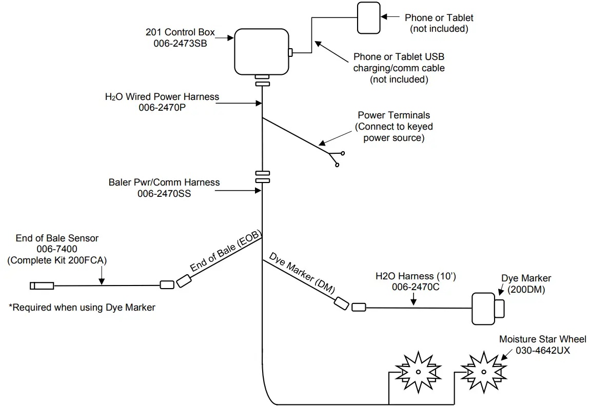
*If needed an optional 8’ Pwr/Comm harness extension is available (not included), part number 006-2470BL2.
Downloading H2O App
The H2O App is available on any Apple or Android device running with the current operating system software and one previous version. Download the app by searching for H2O Sensor. App icon shown right.

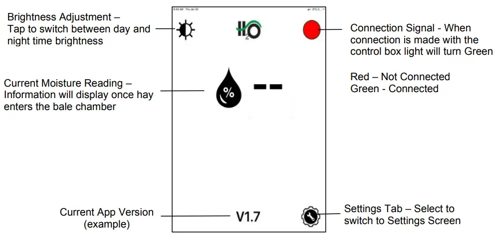
Screen Definitions
Main Screen
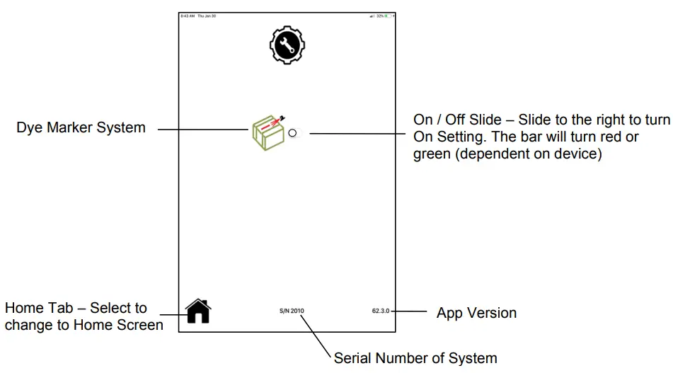
Settings Screen
Operation
After installation of the H2O app, turn the system on by turning the key in the tractor on. When the connection is made the green light on the control box will illuminate.
Reading Moisture
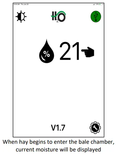
Moisture Range 5-33%

Dye Marker System
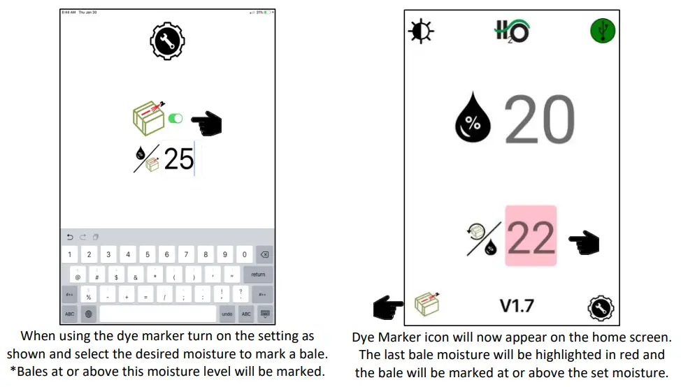
Dye Marker Notes
- When the Dye Marker is activated by the moisture setting it will spray 3 seconds once per End of Bale (EOB) cycle. After an EOB signal the dye marker is then reset to be able to spray again for 3 seconds once on the next bale.
- A full tank of dye is estimated to mark 50-60 bales.
Dye Marker Override
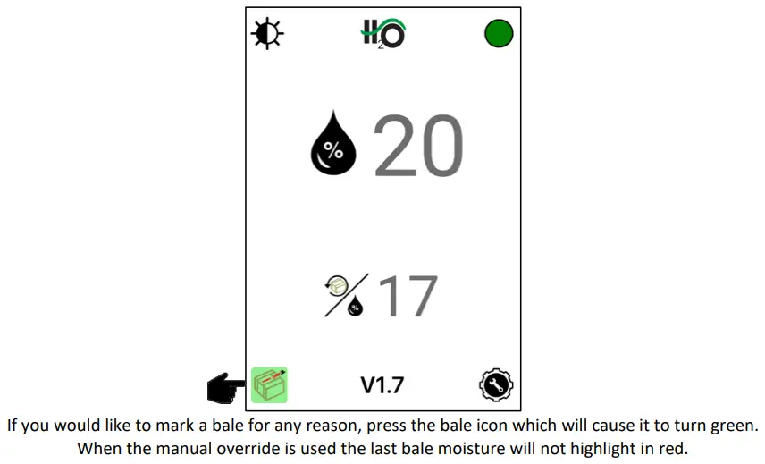
The manual spray function can be used on a bale as many times as preferred in 3 second intervals.
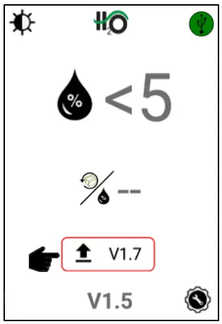
H2O Firmware Update through App
When there is an update available for the H2O system the following information will appear, and the steps listed will need to be followed.
Once an operator downloads the app update (internet connection required) the “update available” symbol will appear along with the version number of the available update once connected to the system.
At this point the system can run without updating if the operator chooses. The icon will simply remain on the screen.
Once the operator decides to perform the software update, they will press the version number or upload arrow to begin.
Internet connection is not required to perform the update to the module once the app is downloaded
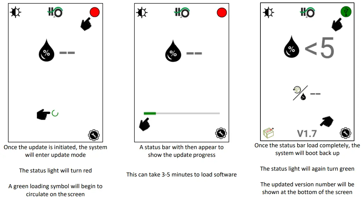
It is recommended for proper communication that the original phone/tablet power cable is used. Many lower cost power cables do not meet requirements to properly charge and communicate to the Harvest Tec H2O module.
Pin Outs
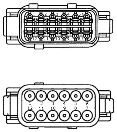
| H2O Wired Moisture Control 006-2473SB Pin 1 Red Module Power Pin 2 Red/Black EOB + Pin 3 Black EOB – Pin 4 Grey Left Moisture Sensor Pin 5 Brown Right Moisture Sensor Pin 6 Purple EOB Signal Pin 7 Yellow CAN + Pin 8 Green CAN – Pin 9 Red/White Dye Marker 12V + Pin 10 Black/White Dye Marker 12V – Pin 11 Blue Dye Marker Prime Pin 12 Black Ground |
| H2O Wired Power Harness 006-2470P Pin 1 Red Module Power Pin 2 Red/Black EOB + Pin 3 Black EOB – Pin 4 Grey Left Moisture Sensor Pin 5 Brown Right Moisture Sensor Pin 6 Purple EOB Signal Pin 7 Yellow Not Used Pin 8 Green Not Used Pin 9 Red/White Dye Marker 12V + Pin 10 Black/White Dye Marker 12V – Pin 11 Blue Dye Marker Prime Pin 12 Black Ground |
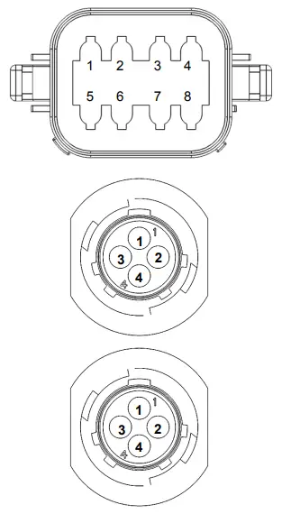
| Baler Communication Harness 006-2470SS Pin 1 Red/Black EOB + Pin 2 Black EOB – Pin 3 Purple Left Moisture Sensor Pin 4 Grey Right Moisture Sensor Pin 5 Brown EOB Signal Pin 6 Red/White Dye Marker 12V + Pin 7 Black/White Dye Marker 12V – Pin 8 Blue Dye Marker Prime |
| End of Bale Sensor (EOB) 006-2471B Pin 1 Brown EOB + Pin 2 Blue EOB – Pin 3 N/A Not Used Pin 4 Black EOB Signal |
| Dye Marker H2O Harness 006-2470C Pin 1 Red DS + Pin 2 Black DS – Pin 3 White DS Prime Pin 4 N/A Not Used |
Parts Breakdowns
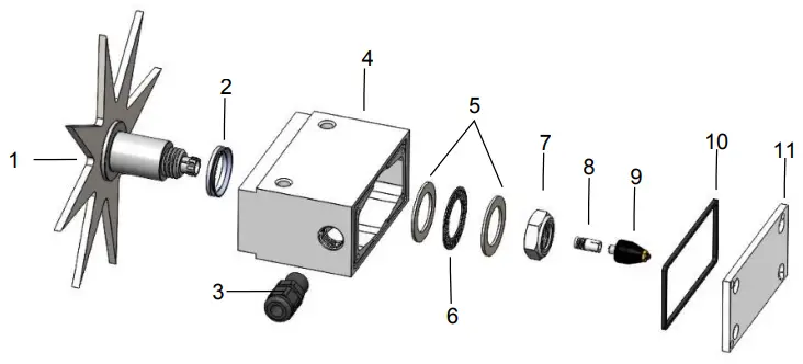
Star Wheel assembly 030-4642UX
| Ref | Description | Part# | Qty |
| 1 | Star Wheel | 006-4642US | 1 |
| Star Wheel w insert (includes 1, 8, & hardware) | 030-4642US | ||
| 2 | Dust Seal (per side) | 006-4642DSL | 2 |
| 3 | Wiring Grommet | 008-0821A | 1 |
| 4 | Block | 006-4642UB | 1 |
| 5 | Thrust Washer | 006-4642TA | 2 |
| 6 | Thrust Bearing | 006-4642TB | 1 |
| 7 | 3/4″ Short Nut | 006-4642U | 1 |
| 8 | Swivel Insert | 006-4642B | 1 |
| 9 | Rotary Swivel | 006-4642A | 1 |
| 10 | Gasket | 006-4642UG | 1 |
| 11 | Block Cover | 006-4642UC | 1 |
| Hardware kit (items 2, 5, 6, 7) | 006-4642UK | ||
| NP | Spacer Plate | 001-6707ES | 2 |
| Star wheel assembly | 030-4642UX | 2 | |
| *Optional Twine Guard-Right | 001-4644 | ||
| *Optional Twine Guard-Left | 001-4644 |
*Can be added if twine excessively makes contact with star wheels
Control Box & Harnesses
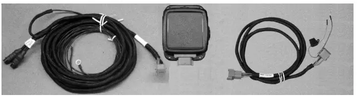
| Ref | Description | Part # | Qty |
| 1 | Baler Pwr/Comm Harness | 006-2470SS | 1 |
| 2 | 201 Series Control Box | 006-2473SB | 1 |
| 3 | Tractor Power Harness | 006-2470P | 1 |
| Optional 8’ power/comm harness extension | 006-2470BL2 | ||
Fixed Chamber End of Bale Sensor Kit
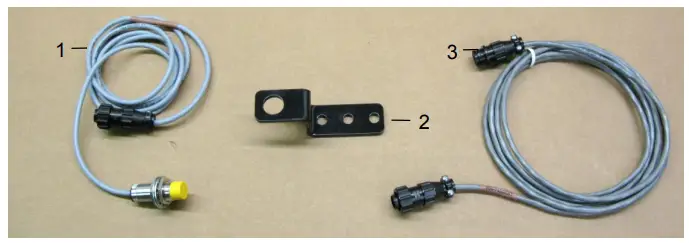
| Ref | Description | Part # | Qty | Ref | Description | Part # | Qty |
| 1 | End of Bale Sensor | 006-7400 | 1 | 3 | EOB Extension | 006-7400EXT | 1 |
| 2 | End of Bale Bracket | 001-4648RB | 1 | Complete Kit | 200FCA |
H2O Dye Marker
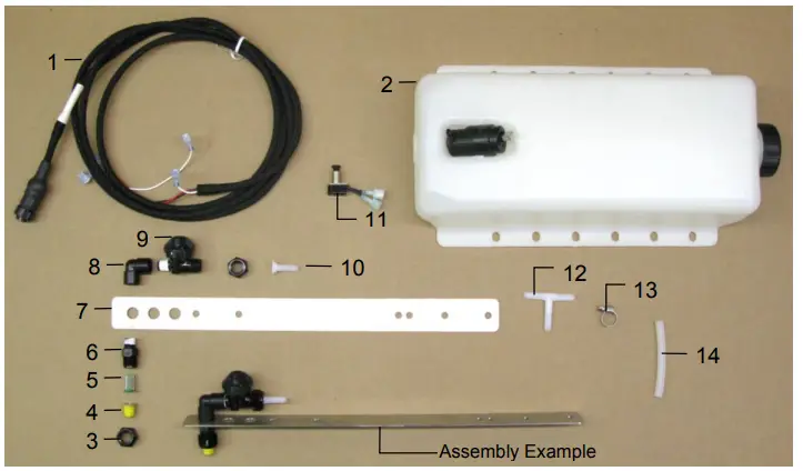
| Ref | Description | Part # | Qty | Ref | Description | Part # | Qty |
| 1 | H2O Harness (10’) | 006-2470C | 1 | 8 | 1/4″ Street Elbow | 003-SE14F | 2 |
| 2 | Tank & Pump | 005-9015 | 1 | 9 | Check Valve | 007-1207VB | 2 |
| 3 | Nozzle Cap | 004-4723 | 4 | 10 | 1/4″ Straight Fitting | 003-A1414VB | 2 |
| 4 | Tip – Brass | 004-TX-5 | 2 | 11 | Push Switch | 006-2850 | 1 |
| 5 | Tip Strainer (Green) | 004-1203-100 | 2 | 12 | 1/4″ All Barb Tee | 003-T1414 | 1 |
| 6 | Nozzle Body | 004-4722 | 2 | 13 | Mini Hose Clamp | 003-9002 | 6 |
| 7 | Nozzle Holder | 001-4215 | 2 | 14 | 1/4″ Hose | 002-9006 | 40 |
| NP | Red Dye | 009-0800 | 1 | ||||
| NP | End of Bale Sensor Kit | 200FCA | 1 | ||||
| Complete Assembly | 030-200DM | ||||||
Harvest Tec Inc. Warranty and Liability Agreement
Harvest Tec, Inc. will repair or replace components that are found to be defective within 12 months from the date of manufacture. Under no circumstances does this warranty cover any components which in the opinion of Harvest Tec, Inc. have been subjected to negligent use, misuse, alteration, accident, or if repairs have been made with parts other than those manufactured and obtainable from Harvest Tec, Inc.
Our obligation under this warranty is limited to repairing or replacing free of charge to the original purchaser any part that in our judgment shows evidence of defective or improper workmanship, provided the part is returned to Harvest Tec, Inc. within 30 days of the failure. If it is determined that a non-Harvest Tec branded hay preservative has been used inside the Harvest Tec applicator system where the failure occurred, then Harvest Tec reserves the right to deny the warranty request at their discretion. Parts must be returned through the selling dealer and distributor, transportation charges prepaid.
This warranty shall not be interpreted to render Harvest Tec, Inc. liable for injury or damages of any kind, direct, consequential, or contingent, to persons or property. Furthermore, this warranty does not extend to loss of crop, losses caused by delays or any expense prospective profits or for any other reason. Harvest Tec, Inc. shall not be liable for any recovery greater in amount than the cost or repair of defects in workmanship.
There are no warranties, either expressed or implied, of merchantability or fitness for particular purpose intended or fitness for any other reason.
This warranty cannot guarantee that existing conditions beyond the control of Harvest Tec, Inc. will not affect our ability to obtain materials or manufacture necessary replacement parts.
Harvest Tec, Inc. reserves the right to make design changes, improve design, or change specifications, at any time without any contingent obligation to purchasers of machines and parts previously sold.
HARVEST TEC, INC.
P.O. BOX 63
2821 HARVEY STREET HUDSON, WI 54016 USA PHONE: 715-386-9100
FAX: 715-381-1792
Email: [email protected]
DECLARATION OF INCORPORATION

MANUFACTURER:
Harvest Tec Inc.
2821 Harvey St.
P.O. Box 63
Hudson, WI 54016, U.S.A.
REPRESENTATIVE ESTABLISHED IN COMMUNITY:
Profitable Farming Company
Middle Barlington, Roborough
Winkleigh, Devon, EX19 8AG
ENGLAND
The person above certifies and declares that:
VIRTUAL MACHINE: Equipment mounted on a farm press to monitor moisture.
MODEL: H2O Sensor-Owners-201SS-19-Imp&Metric
BRAND: Harvest Tec
SERIAL NUMBER:
This Harvest Tec moisture system meets the Directive 2006/42/EC of the European Parliment and the Council of 17 May 2006 and other applicable European Directives including Directive 2014/53/EU on the Radio Equipment Directive and 2014/30/EU
The Harvest Tec moisture system will be turned on after being installed on a farm press which has been declard in conformity with the Machinery Directive.
Person in the community authorized to provide information on the partly completed machinery and making this statement:
Richard Snell, President, Profitable Farming Company Signed on May 21, 2011: Middle Barlington, Roborough Winkleigh, Devon, EX19 8AG
ENGLAND


