HARVEST TEC 300SS Moisture Only Kit for Small Square Balers Instruction Manual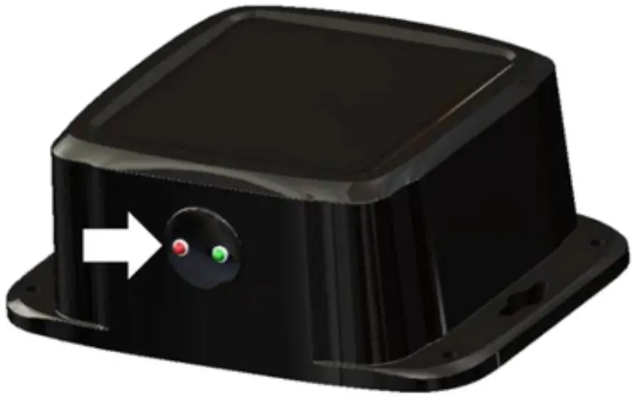
Introduction
Congratulations and thank you for purchasing a Harvest Tec Model 300SS moisture only kit. Please read this manual carefully to ensure correct steps are taken to attach the system to the baler. This applicator is designed to read moisture through an Apple iPad. A parts break of the system is located in the back of the manual.
System Requirements
Made for iPad® running the current iOS operating system *iPad is a trademark of Apple Inc., registered in the U.S. and other countries. 300 Series Applicators with serial number before THS07000 will require the THS to be sent to Harvest Tec for a required update in order to use the iPad Integration Module (030-6670C).
Hay App version must be at least 2.7.1 (or higher) to operate with the iPad Integration Module (030-6672C)
Tools Needed
- Standard socket set
- Side cutter
- Crescent wrench
- Metal drilling and cutting tools
- Standard screw driver or 5/16”
- Hose cutter
- Hammer
- Center Punch
Installation of iPad Integration Control
Locate a safe location in the cab of the tractor to place the iPad Integration Control (030-6672C). Recommended location is securely fastened out of the operators way in a location that is close enough to
reach with the iPad cord.
Connect the Power / Communication harness (006-6650TM(E)) to the bottom of the receiver.
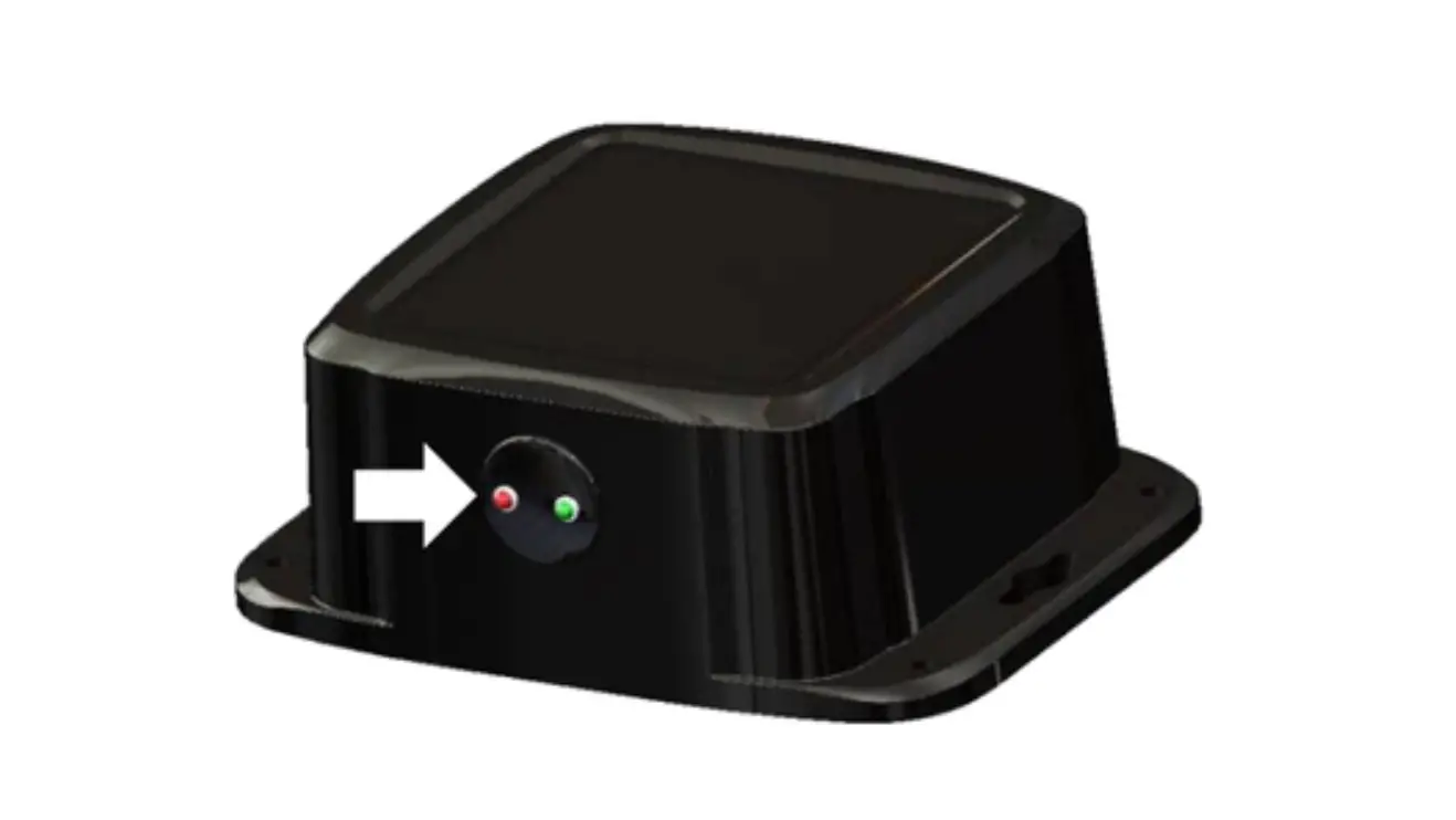
To operate the applicator, plug the iPad cord into the communication port indicated by: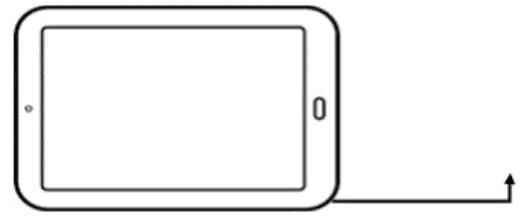
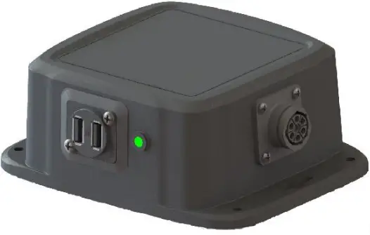

iPad Integration Control Light Signals
Green Slow Blink – Power supplied to the applicator system and the unit is going through its startup process.
This will take approximately 25-35 seconds.
Green Double Blink – Indicating the iPad module recognizes the iPad but the app is not open or connected.
Green Solid Light – Module is connected to the app and is ready to operate.
*Recommended to use the USB cable included with the applicator kit (006-6672USBC)
Bluetooth Receiver Lights
Pre-2020 applicators’ equipped with Bluetooth receivers (030-6672B) are now equipped with lights to indicate both power and Hay App connection on the Apple iPad. Clean light regularly Blinking Lights – System is waiting for the processor to connect, which could take up to 35 seconds.
Red Light – The Bluetooth receiver has power.
Green Light – The Bluetooth receiver is connected to the Hay App.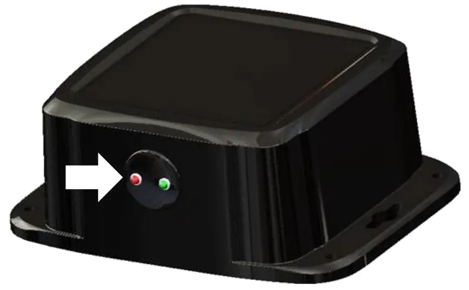
Made for Apple iPad badge
Use of the Made for Apple iPad badge means that an accessory has been designed to connect specifically to the Apple product(s) identified in the badge and has been certified by the developer to meet Apple
performance standards. Apple is not responsible for the operation of this device or its compliance with safety and regulatory standards.
Please note that the use of this accessory with an Apple product may affect wireless performance.
Installation of the 300SS
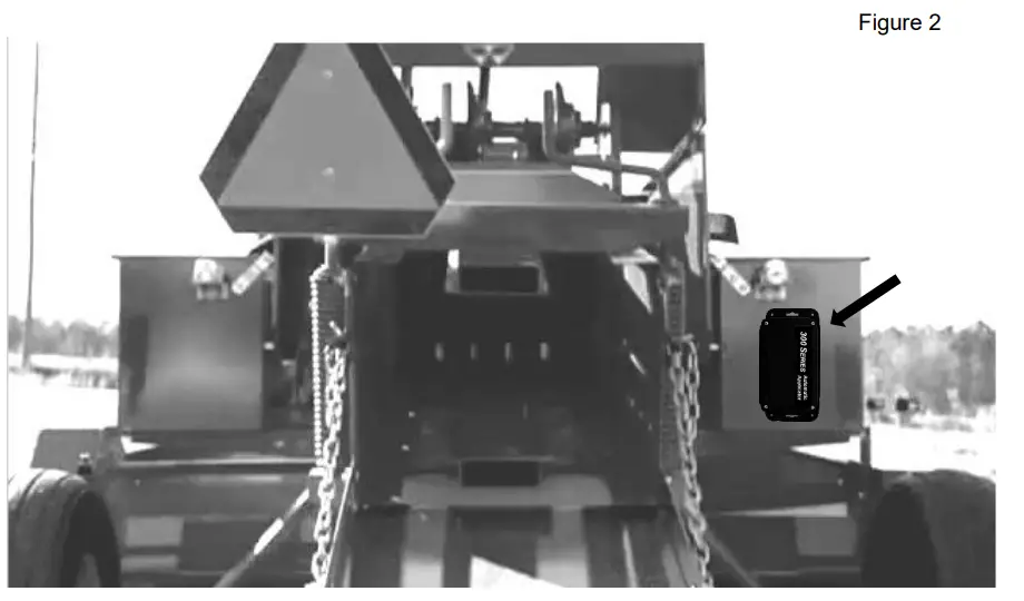
Locate the controls package. Select a mounting location for the Three Hundred Series (THS) control box (006- 3671SS) easily accessible that is away from moving parts and access panels. Check before drilling to ensure nothing will be damaged on the opposite side of the THS. After selecting the location for the THS, use the THS as a drill guide and mark the four mounting holes.
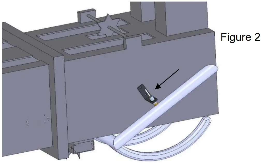
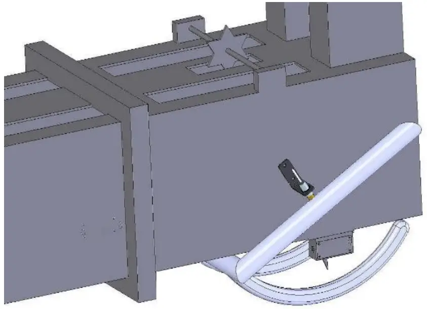
Drill the four mounting hole locations to 3/16″ (5mm) in size. The locations shown in figures 1 and 2 are examples of mounting the THS on the twine box (looking at the back of the baler). Use the supplied 10/32 x 3/4″ Phillips flathead machine screws, NY lock washers and nuts to mount the control box.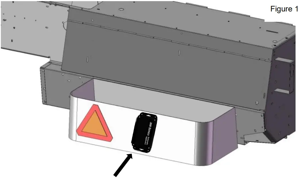
Installation of End of Bale Sensor
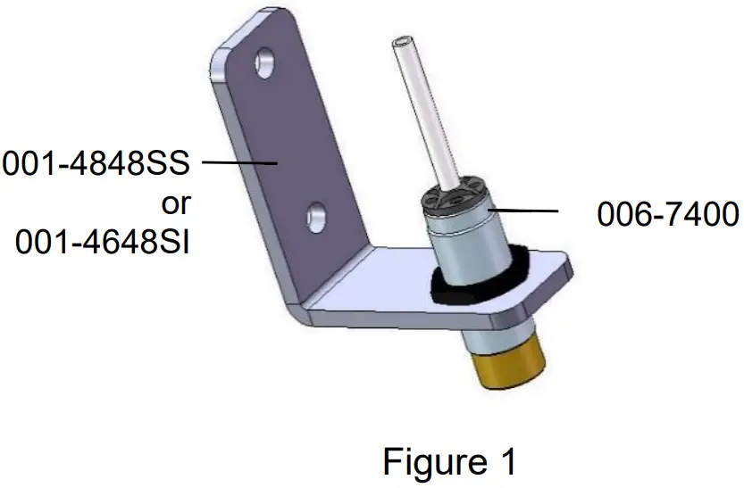
Mount the 006-7400 sensor to the mounting bracket 001-4648SI for AGCO as shown below (Figure 1). Case IH, New Holland, & John Deere and other balers will use bracket 001-4648SS. Mount the assembly on the right side of the baler chamber. The face of the sensor needs to be parallel to the arm attached to the needles (Figure 2). Mark and drill two 3/8” (10mm) holes. Install the sensor using two 5/16” x 1“ Allen head bolts, locks, nd nuts. The end of the sensor needs to be no greater than 1/4” (7mm) away from the needle arm. Tighten nuts on sensor after adjustment.
Installation of Star Wheels
The pair of star wheels will need to mount on the bottom side as close to the front of the bale chute as possible and at least 3/8″ (10mm) away from any metal. They will need to maintain a safe distance away from the twine.
The star wheels will require two holes to be drilled per block, when drilling make sure to keep the wheel square to the bale chamber. Any angle will cause stress on the wheel and will eventually cause the wheel to work itself out of the block. Some balers may require a notch cut on the bottom of the bale chamber to mount the star wheels as close to the front of the chamber as possible.
Use the supplied bolts and place the carriage head inside of the bale chamber followed by lock and nut. Next attach the star wheels to the bolts followed by flat washer, lock washer and nut.
First, remove the cover from the star wheel block and use a 1/4″ (7mm) nut driver to remove the nut from the electronic swivel. Next, run the star wheel sensor wire through the black grommet and place the eye terminal on the star wheel sensor. Tighten the eye loop with the nut on the sensor and put the star wheel cover back on the base. Next, tighten the grommet to form a tight seal around the wire. Once the star wheel connection is complete, run the harness along the baler frame to the Three Hundred Series (THS) controller.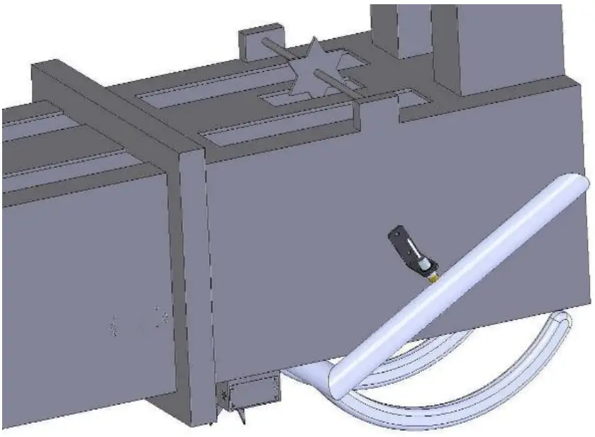
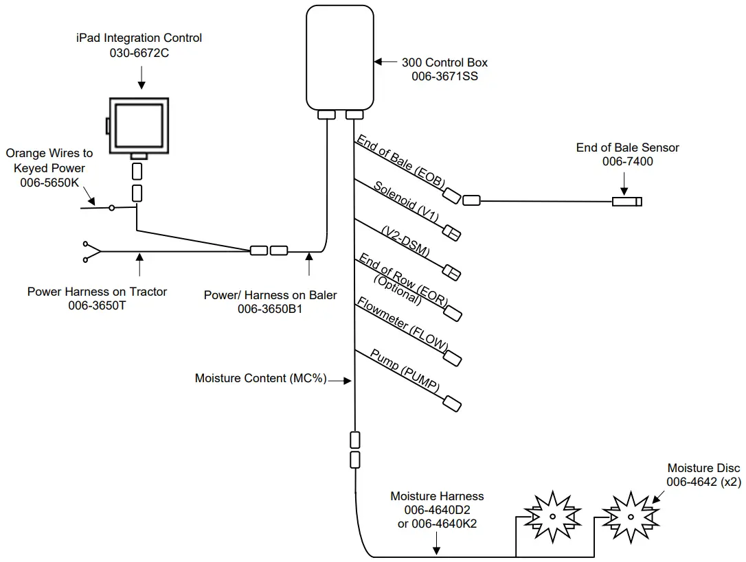
Wiring Diagram 300SS
 Connect the power harness (006-3650T) to the tractor battery (12 volt) using the red wire with fuse to the positive side and the black wire to the negative.
- The power harness must be connected to the battery! The unit will draw more amps than convenience outlets can handle. Any modifications of the power harness will void systems warranty. CONTACT HARVEST TEC BEFORE MODIFICATIONS.
- This unit will not function on positive ground tractors.
- If the unit loses power while operating it will not keep track of accumulated pounds of product used.
- The power harness on the tractor (006-3650T) will run from the tractor battery to the hitch. The power harness on the baler (006-3650B1) will connect to the tractor power harness (006-3650T) at the hitch.
- Connect the keyed power wire (006-5650K) to a keyed power source on the tractor. The keyed power wire must connect to a keyed source or the unit will not power up correctly.
- Attached the iPad Integration Control (030-6672C) to the tractor power harness (006-3650T).
- Attach the End of Bale (EOB) connection on the controller to the End of Baler Sensor (006-7400).
System wiring diagram
| Harness | Color |
| EOB | Brown |
| V1 | White (Delphi Connector) |
| EOR | Yellow |
| FLOW | White |
| V2-DSM | White (Delphi Connector) |
| Pump | Orange |
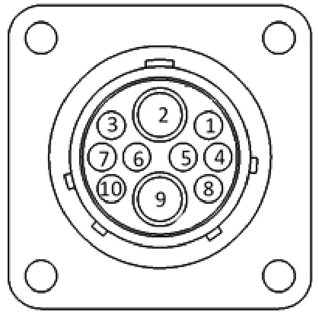
Pin Outs
Power Harness 006-3650T at Tractor Hitch
- Pin 1 Red +12V Power to BLE
- Pin 2 Red +12V Power to THS
- Pin 3 Orange Keyed Power
- Pin 4 Not Used
- Pin 5 Green HT Can Low
- Pin 6 Yellow HT Can Hi
- Pin 7 Not Used
- Pin 8 Black Ground from BLE
- Pin 9 Black Ground from THS
- Pin 10 Not Used

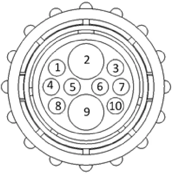
Power Harness 006-3650B1 at Baler Hitch
- Pin 1 Red +12V Power to BLE
- Pin 2 Red +12V Power to THS
- Pin 3 Orange Keyed Power
- Pin 4 Not Used
- Pin 5 Green HT Can Low
- Pin 6 Yellow HT Can Hi
- Pin 7 Not Used
- Pin 8 Black Ground from BLE
- Pin 9 Black Ground from THS
- Pin 10 Not Used

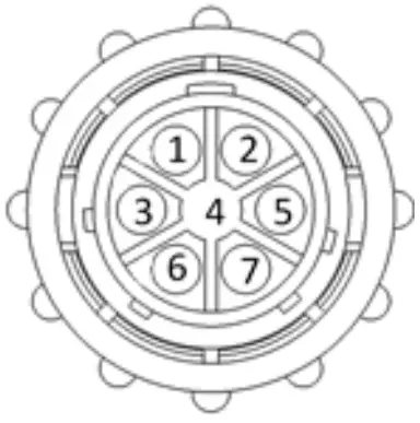
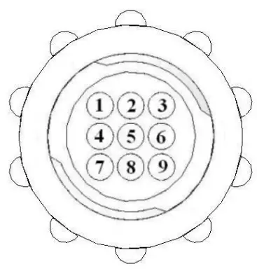
iPad Integration Control / BLE on Harness 006-3650T
- Pin 1 Red +12V Power for BLE
- Pin 2 Black Ground for BLE
- Pin 3 Yellow HT Can Low
- Pin 4 Not Used
- Pin 5 Green HT Can Hi
- Pin 6 Not Used
- Pin 7 Not Used

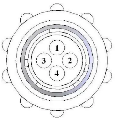
End of Bale Sensor at 300 Controller Harness
- Pin 1 Brown Sensor Power
- Pin 2 Blue Sensor Ground
- Pin 3 N/A
- Pin 4 Black Signal from Sensor

Flow Meter at 300 Controller Harness
- Pin 1 White +5-12V Power
- Pin 2 Brown Ground
- Pin 3 Green Signal
- Pin 4 Not Used
End of Row Sensor at 300 Controller Harness
- Pin 1 Red/White +12V Power
- Pin 2 Black/White Ground
- Pin 3 Yellow Signal
- Pin 4 N/A
Moisture Sensor connection at 300 Controller Harness
- Pin 1 Not Used
- Pin 2 Not Used
- Pin 3 Not Used
- Pin 4 Not Used
- Pin 5 Not Used
- Pin 6 Not Used
- Pin 7 Not Used
- Pin 8 Blue Signal for Sensor 1
- Pin 9 Blue Signal for Sensor 2
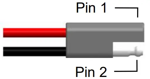
Pump connection at 300 Controller Harness
- Pin 1 Red Power to Pump
- Pin 2 Black Ground to Pump


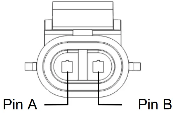
Solenoid Connection at 300 Controller Harness
- Pin A Black Solenoid Pause
- Pin B White Solenoid Ground
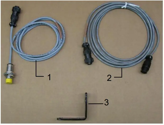
Control Box and Wiring Harnesses
| Ref | Description | Part# | Qty | Ref | Description | Part# | Qty |
| 1 | Power lead baler 20’ | 006-3650B1 | 1 | 5 | 300 Series Controller | 006-3671SS | 1 |
| 2 | Power lead tractor | 006-3650T | 1 | 6 | Dust Plugs | 006-5651Plugs | 1 |
| 3 | Key Switch Wire | 006-5650K | 1 | 7 | Power lead baler 30’ (AGCO) | 006-3650B2 | 1 |
| 4 | iPad Int. Control | 030-6672C | 1 | NP | USB Cable | 006-6672USBC | 1 |
| Complete Assembly (1-6) | 030-362CPA | ||||||
| Complete Assembly (2-7) | 030-362CPB |
End of Bale Sensor Kit A
| Ref | Description | Part # | Qty |
| 1 | End of Bale Sensor | 006-7400 | 1 |
| 2 | EOB Extension | 006-7400EXT | 1 |
| 3 | End of Bale Bracket | 001-4648SS | 1 |
| Complete Assembly | EOB-SS-A |
End of Bale Sensor Kit B
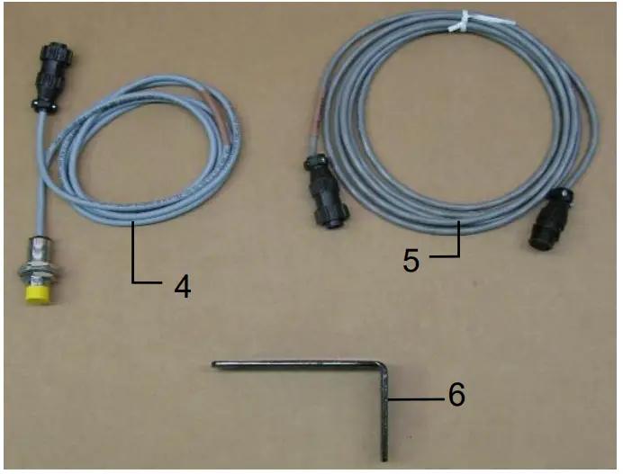
| Ref | Description | Part # | Qty |
| 4 | End of Bale Sensor | 006-7400 | 1 |
| 5 | EOB Extension | 006-7400EXT | 1 |
| 6 | End of Bale Bracket | 001-4648SI | 1 |
| Complete Assembly | EOB-SS-B |
Star Wheel Sensors
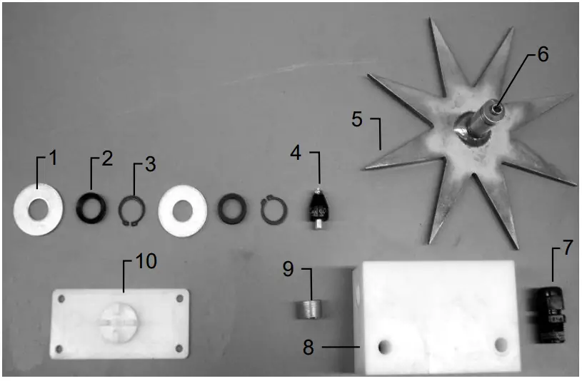
| Ref | Description | Part# | Qty |
| 1 | Washer (per side) | 006-4642K | 2 |
| 2 | Dust Seal (per side) | w/006-4642K | 1 |
| 3 | Snap Ring (per side) | w/006-4642K | 2 |
| 4 | Swivel | 006-4642A | 2 |
| 5 | Star Wheel | 030-4641E | 2 |
| 6 | Insert | w/ Ref # 5 | 2 |
| 7 | Wiring grommet | 008-0821A | 2 |
| 8 | Star wheel block | 006-4641A | 2 |
| 9 | Plug Fitting | 003-F38 | 2 |
| 10 | Block Cover | 006-4641B | 2 |
| 1-10 | Star wheel assembly | 030-4642 | 2 |
Moisture Harness
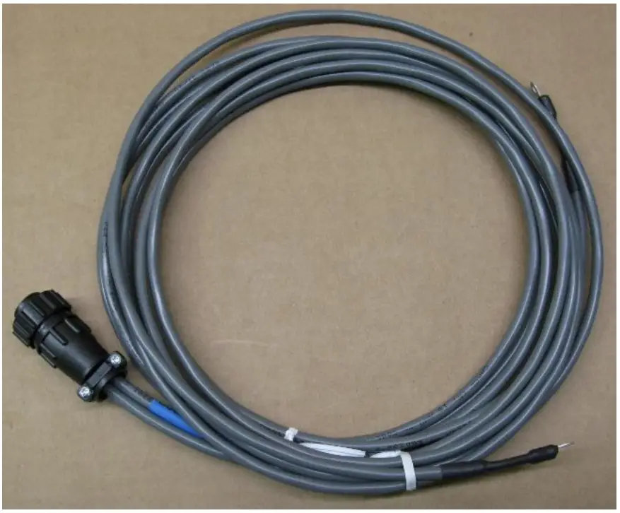
| Ref | Description | Part # | Qty |
| NP | Moisture Harness (10’) | 006-4640D2 | 1 |
| NP | Moisture Harness (15’) | 006-4640K2 | 1 |
Optional iPad Mini Mounting Kit (030-2014MK)
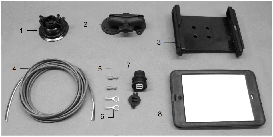
| Ref | Description | Part # | Qty |
| 1 | Suction cup mount | 001-2012SCM | 1 |
| 2 | Ram mount | 001-2012H | 1 |
| 3 | iPad Mini® spring load cradle (Mini 4) | 001-2012SLC | 1 |
| 4 | 16 gauge power wire | 006-4723P | 1 |
| 5 | Female spade connector | Hardware | 2 |
| 6 | Eye loop connector | Hardware | 2 |
| 7 | iPad Mini Charger 12V | 001-2012P | 1 |
| 8 | iPad Mini 4 case | 001-2012C4 | 1 |
| NP | 4 amp fuse | Hardware | 1 |
| Mounting Kit Assembly | 030-2014MK | ||
| (Includes All Parts) | |||
Installation Instructions
- Identify 12V power source for wires to connect.
- Eye loops included if wiring directly to the battery is desired.
- Test for key power source if preferred to have power to the USB shut off with the key.
- Once power source is identified, cut wires to desired length.
- Crimp the two supplied quick connectors onto each the white and black wire.
- Remove the round locking plastic nut from USB plug before connecting the wires. Black (+) White (-).
- The wires will then be hooked to the designated terminals on the bottom of the USB plug
- Drill a 1 1/8” hole in the preferred mounting location. Be sure to clean any sharp edges after drilling.
- Feed the wires through the mounting hole.
- If using the round plastic nut to secure plug in place, slide the nut back over the wiring before connecting the wires to powered source.
- Connect the wires to the identified power source if easier to do so before tightening the plug into place.
- Tighten plug using either the round plastic nut or mounting plate and two screws, both options supplied.
- Once connected, hook a USB charging cord into the plug and connect a mobile device/tablet to ensure the plug is operating as you wish (key power working properly if necessary).
NOTE: This plug is not designed to charge two iPads. System damage could occur if this is attempted.
System will charge a mobile phone and iPad simultaneously without problem.
iPad mini is a trademark of Apple Inc., registered in the U.S. and other countries.
Harvest Tec LLC. Warranty and Liability Agreement
Harvest Tec, LLC. will repair or replace components that are found to be defective within 12 months from the date of manufacture. Under no circumstances does this warranty cover any components which in the opinion of Harvest Tec, LLC. have been subjected to negligent use, misuse, alteration, accident, or if repairs have been made with parts other than those manufactured and obtainable from Harvest Tec, LLC.
Our obligation under this warranty is limited to repairing or replacing free of charge to the original purchaser any part that in our judgment shows evidence of defective or improper workmanship, provided the part is returned to Harvest Tec, LLC. within 30 days of the failure. If it is determined that a non-Harvest Tec branded hay preservative has been used inside the Harvest Tec applicator system where the failure occurred, then
Harvest Tec reserves the right to deny the warranty request at their discretion. Parts must be returned through the selling dealer and distributor, transportation charges prepaid.
This warranty shall not be interpreted to render Harvest Tec, LLC. liable for injury or damages of any kind, direct, consequential, or contingent, to persons or property. Furthermore, this warranty does not extend to loss of crop, losses caused by delays or any expense prospective profits or for any other reason. Harvest Tec,
LLC. shall not be liable for any recovery greater in amount than the cost or repair of defects in workmanship.
There are no warranties, either expressed or implied, of merchantability or fitness for particular purpose intended or fitness for any other reason.
This warranty cannot guarantee that existing conditions beyond the control of Harvest Tec, LLC. will not affect our ability to obtain materials or manufacture necessary replacement parts.
Harvest Tec, LLC. reserves the right to make design changes, improve design, or change specifications, at any time without any contingent obligation to purchasers of machines and parts previously sold.
Revised 5/22
Customer Support
HARVEST TEC, LLC.
P.O. BOX 63
2821 HARVEY STREET
HUDSON, WI 54016
PHONE: 715-386-9100
1-800-635-7468
FAX: 715-381-1792
Email: [email protected]


