HARVEST TEC 600SS Moisture Sensor Kit for Small Square Installation Guide
Introduction
Thank you for purchasing a Harvest Tec Model 600SS Moisture Monitor System. This 600SS Moisture
Monitoring System has been designed to be operated through an Apple iPad (not included) using the Hay App.
As well as the option to plug directly into most tractors that have an ISOBUS Monitor. The 600SS Moisture Monitoring System offers these advantages by operating through an Apple iPad:
- Large bright, clear, colorful display
- More durable and can be read in bright sunlight
- Can be used for multiple other uses than just the applicator display
- Option to tie-into the tractor ISOBUS system
The 600SS Moisture Monitor kit includes the following parts: Dual Channel Processor (DCP), Moisture Sensors, Harnesses. A parts break down for the 600SS Moisture Monitoring System is included in the back of
this manual. If you do have questions please bring this manual into the dealership.
Right and Left sides are determined by facing in the direction of forward travel.
*Made for iPad® (3rd through Pro 2nd generation), running the current iOS operating system or one version previous required for iPad option *iPad is a trademark of Apple Inc., registered in the U.S. and other countries.
**600 Series Applicators with serial number before DCP27000 will require the DCP to be sent to Harvest Tec for a required update in order to use the iPad Integration Module (030-6672C).
*Hay App version must be at least 2.7.1 (or higher) to operate with the iPad Integration Module
If choosing to operate the unit though the ISOBUS monitor, part number 006-6670A will need to be ordered through your local equipment dealer.
Tools Needed:
- Standard wrench set
- Electric drill and bits
- Side cutter
- Standard nut driver set
- Standard socket set
- Hammer
- Center punch
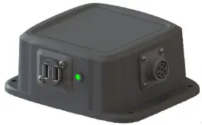
Installation of the Dual Channel Processor
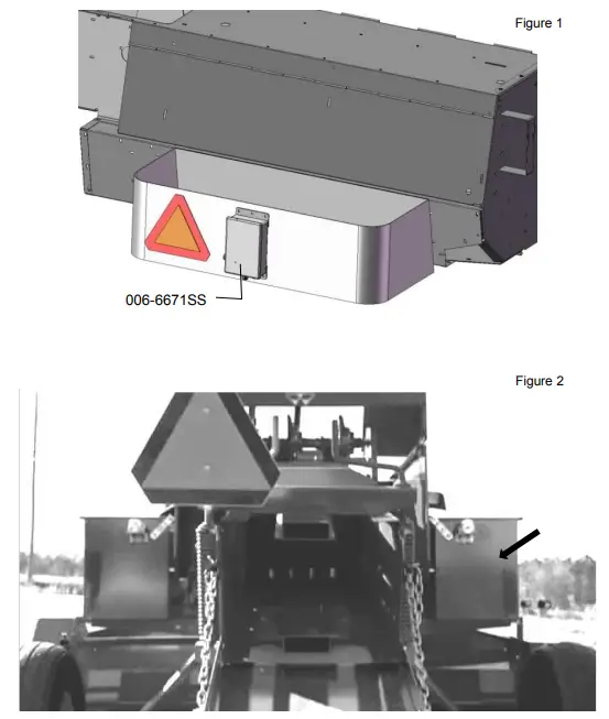
Follow the instructions below to mount the Dual Channel Processor (DCP) on to your specific baler model and type. The locations shown are examples of mounting the DCP on the twine box (looking at the back of the baler). Mark and drill the four 3/8” (10mm) holes and install DCP with four 5/16” x 1” bolts, locks, flats and nuts. Mount the DCP on the back of the twine box on the right side. Figure 1 & 2
Two-Tie Balers
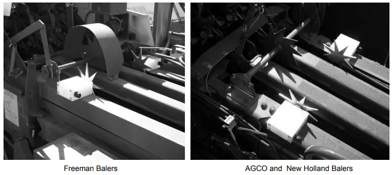
The pair of star wheels will need to mount on the bottom side as close to the front of the bale chute as possible and at least 3/8″ away from any metal. They will need to maintain a safe distance away from the twine.
The star wheels will require two holes to be drilled per block, when drilling make sure to keep the wheel square to the bale chamber. Any angle will cause stress on the wheel and will eventually cause the wheel to work itself out of the block. Some balers may require a notch cut on the bottom of the bale chamber to mount the star wheels as close to the front of the chamber as possible. Use the template in back of manual to aid in installation.
Use the supplied bolts and place the carriage head inside of the bale chamber followed by lock and nut. Next attach the star wheels to the bolts followed by flat washer, lock washer and nut. The right side star wheel will have the bale rate sensor bolted to the bottom of the block.
First, remove the cover from the star wheel block and use a 1/4″ (7mm) nut driver to remove the nut from the electronic swivel. Next, run the star wheel sensor wire through the black grommet and place the eye terminal on the star wheel sensor. Tighten the eye loop with the nut on the sensor and put the star wheel cover back on the base. Next, tighten the grommet to form a tight seal around the wire. The sensor with the longer sensor wire should say “FRONT”, which indicates it should be placed in the front sensor hole. The sensor wire with the shorter wire should say “BACK.” The tip of the sensor should be placed no more than 1/4” (7mm) away from the star wheel teeth and no less than 1/8” from the star wheel teeth.
Each sensor will have an LED light located on the sensor by the sensor holder. Once the unit is powered up spin the wheel and make sure that both led lights turn on and off. If they don’t turn on and off, adjustments may need to be made. Once the star wheel connection is complete, run the harness along the baler frame to the Duel Channel Processor (DCP). See wiring installation.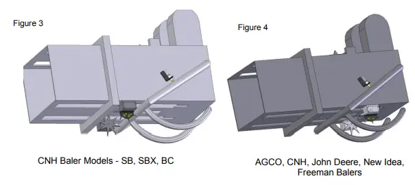
Three-Tie Balers
The pair of star wheels will need to mount on the top as close to the knotters as possible and at least 3/8″ away from any metal. They will need to maintain a safe distance away from the twine.
The star wheels will require two holes to be drilled per block, when drilling make sure to keep the wheel square to the bale chamber. Any angle will cause stress on the wheel and will eventually cause the wheel to work itself out of the block. A template can be found in the back of the manual to help with the placement of the star wheel.
Use the supplied 5/16” allen head carriage bolts and place the carriage head inside of the bale chamber followed by lock and nut. Next place the 001-4644SS prox sensor holder (not pictured) on top of the star wheel located on the right side of the bale chamber. Secure the prox sensor holder and star wheel entire block using nuts, locks, and flat washers.
Remove the four screws holding the plastic cover and attach one wire eye loop per star wheel through the grommet and tighten down with the nut attached to the swivel. Reinstall the cover and run the wires up to the pump plate. You will need to use zip ties to attach the wires so as to not interfere with normal baler use.
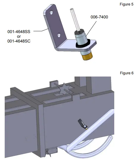
Installation of End of Bale Sensor
The end of bale sensor determines the position of the needles on the baler. When the needles cycle, the sensor communicates this information to the Dual Channel Processor. This information is used for job records and will be used by the optional Bale Identification system. Follow the steps below for your baler to mount the sensor.
Mount the 006-7400 sensor to the mounting bracket 001-4648SS for Case IH, New Holland, & John Deere or 001-4648SC for AGCO as shown below. Figure 5
Mount the assembly on the right side of the baler chamber. The face of the sensor needs to be parallel to the arm attached to the needles. Drill two 3/8” (10mm) holes (Figure 6). Install sensor using two 5/16” x 1 “ Allen head bolts, locks, and nuts. The end of the sensor needs to be no greater than 1/4” away from the needle arm. Tighten both nuts on the sensor after the adjustment.
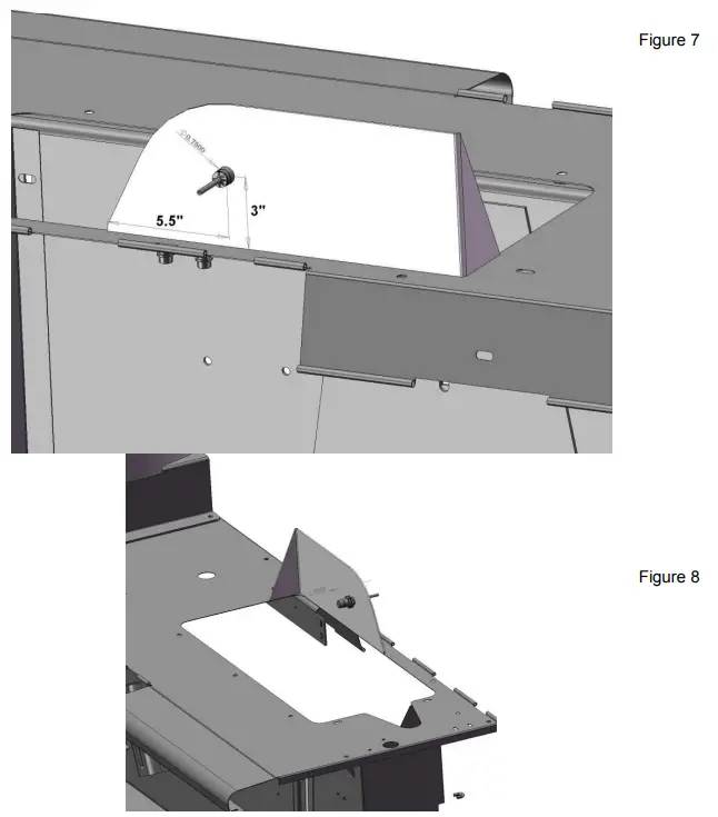
Installation of Stroke Counter Sensor
The stroke counter sensor determines how many plunger strokes were used to make a bale. This sensor works in combination with the end of bale sensor and sends the information to the DCP. The information will be saved in your Job Records and will also be displayed on the screen in Automatic or Manual mode. Follow the steps below for your baler to mount the sensor.
CaseIH Baler Models – SBX 530, 540, 550, SB531, SB541, SB551
New Holland Baler Models – 570, 575, 580, BC5060, BC5070, BC5080
Locate the steel behind the gathering fork (Figure 7). Figure 7 shows the steel from the back of the baler, Figure 8 is the front-left view. Mark and drill the 3/4” (19mm) hole for the sensor to mount through. With the tractor turned off and the PTO disconnected from the tractor, rotate the baler fly wheel by hand until the gathering fork arm is directly in front of the 3/4” (19mm) hole. Install the sensor and position so that the end of the sensor is 1/4” (7mm) away from the fork. Tighten the nuts on both sides of the sensor after the adjustment.
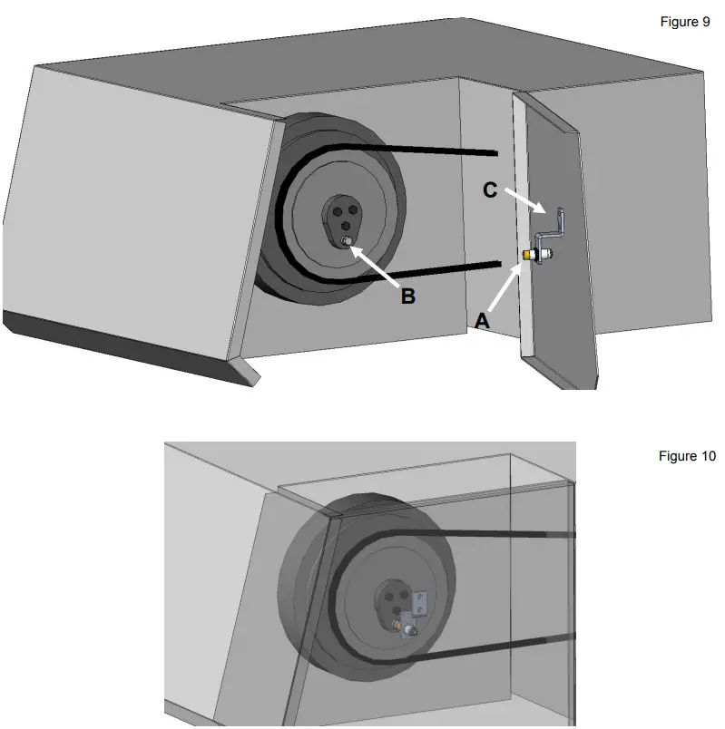
AGCO, New Idea, Massey Ferguson
Open the left access panel as shown in Figure 9. The end of the sensor (A) will be aligned with the bolt head
(B). With the tractor turned off and the PTO disconnected from the tractor, rotate the balers flywheel so that the bolt head (B) is at it lowest position. Locate bracket 001-4648SC (C) and loosely install the sensor. Align the end of the sensor over the bolt head (B) and mark the two 3/8” (10mm) holes that will need to be drilled to mount the bracket (C). Install the bracket using two 5/16 x 1” bolts, flats, locks, and nuts. Close the access panel (Figure 8) and adjust the sensor so that it is 1/4” (7mm) away from the bolt head (B). Tighten the nuts on the sensor after the adjustment is made. Leave enough slack in the wire to allow the access door to function (Figure 10).
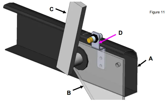
New Holland 200, 300 Series, 565 and BC5050
John Deere, Welger Balers, Freeman
Locate the gathering fork area shown below on the baler (Figure 11). The area is shown standing at the front of the baler and looking to the back. The bracket will mount on the steel next to the bearing on the gathering fork.
Point (A) is the sheet metal on the back of the baler, point (B) is the steel that holds the gathering fork bearing, point (C) is the back arm on the gathering fork.
Locate the sensor bracket D (001-4648RB). Mark and drill two 3/8” (10mm) holes to mount the bracket. Attach the bracket using two 5/16 x 1” bolts, flats, locks, and nuts. Loosely install the sensor into the bracket. With the tractor turned off and the PTO disconnected from the tractor, rotate the flywheel by hand to get the end of the sensor lined up with the gathering fork (C). The end of the sensor need to be 1/4” (7mm) away from gathering fork. After the adjustments are made tighten both nuts on the sensor.
Installation of iPad Integration Control
Locate a safe location in the cab of the tractor to place the iPad Integration Control (030-6672C). Recommended location is securely fastened out of the operators way in a location that is close enough to reach with the iPad cord.
Connect the Power / Communication harness (006-6650TM(E)) to the bottom of the receiver.
To operate the applicator, plug the iPad cord into the communication port indicated by:

iPad Integration Control Light Signals
Green Slow Blink – Power supplied to the applicator system and the unit is going through its startup process.
This will take approximately 25-35 seconds.
Green Double Blink – Indicating the iPad module recognizes the iPad but the app is not open or connected.
Green Solid Light – Module is connected to the app and is ready to operate.
Recommended to use the USB cable included with the applicator kit (006 6672USBC)
Bluetooth Receiver Lights
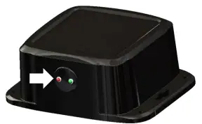
Pre-2020 applcaitors equipped with Bluetooth receivers (030-6672B) are now equipped with lights to indicate both power and Hay App connection on the Apple iPad. Clean light regularly
Blinking Lights – System is waiting for the processor to connect, which could take up to 35 seconds.
Red Light – The Bluetooth receiver has power
Green Light – The Bluetooth receiver is connected to the Hay App.
**600 Series Applicators with serial number before DCP27000 will require the DCP to be sent to Harvest Tec for a required update in order to use the iPad Integration Module (030-6672C).
Hay App version must be at least 2.7.1 (or higher) to operate with the iPad Integration Module
*Made for Apple iPad badge
Use of the Made for Apple iPad badge means that an accessory has been designed to connect specifically to the Apple product(s) identified in the badge and has been certified by the developer to meet Apple performance standards. Apple is not responsible for the operation of this device or its compliance with safety and regulatory standards.
Please note that the use of this accessory with an Apple product may affect wireless performance.
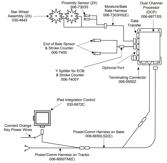
Wiring Diagram
A. Locate the tractor power/communication harness (006-6650TM(E)).
B. Connect the red power wire with the 50 amp fuse to the positive side of the battery (12 volt).![]()
a. The power harness must be connected to the battery! The unit will draw more amps than convenience outlets can handle.
b. This unit will not function on positive ground tractors.
c. If the unit loses power while operating it will not keep track of accumulated pounds of product used and bale records.
C. Connect the black ground wire to frame of tractor or negative side of battery (12 volt).
D. Connect the iPad Integration Control (030-6672C) to the Communication Harness (006-6650TM(E)).
E. Connect the key power orange wire to a keyed power source.
Pin Outs
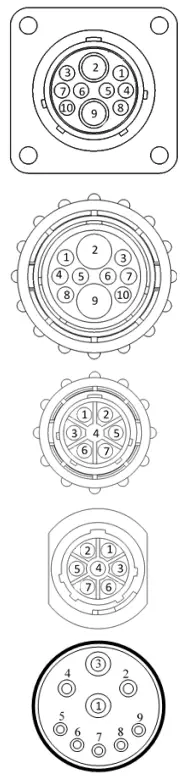
Power/Comm Harness 006-6650TM(E) at Hitch
| Pin 1 | Red | +12V Power to TSD |
| Pin 2 | Red | +12V Power to DCP |
| Pin 3 | Orange | Keyed Power |
| Pin 4 | Gray | Shield |
| Pin 5 | Green | HT Can Low |
| Pin 6 | Yellow | HT Can Hi |
| Pin 7 | Orange | Can1 Hi |
| Pin 8 | Black | Ground from TSD |
| Pin 9 | Black | Ground from DCP |
| Pin 10 | Blue | Can1 Low |
Power/Comm Harness 006-6650LS2(E) at Hitch
| Pin 1 | Red | +12V Power to TSD |
| Pin 2 | Red | +12V Power to DCP |
| Pin 3 | Orange | Keyed Power |
| Pin 4 | Gray | Shield |
| Pin 5 | Green | HT Can Low |
| Pin 6 | Yellow | HT Can Hi |
| Pin 7 | Orange | Can1 Hi |
| Pin 8 | Black | Ground from TSD |
| Pin 9 | Black | Ground from DCP |
| Pin 10 | Blue | Can1 Low |
iPad Integration Control / BLE on Harness 006-6650TM(E)
| Pin 1 | Red | +12V Power from DCP |
| Pin 2 | Black | Ground |
| Pin 3 | Yellow | HT Can Low |
| Pin 4 | Gray | Shield |
| Pin 5 | Green | HT Can Hi |
| Pin 6 | Orange | Can1 Hi |
| Pin 7 | Blue | Can1 Low |
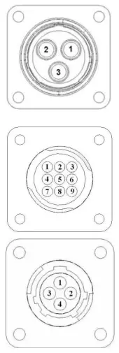
ISOBUS Plug 006-6670A Baler Side
| Pin 1 | N/A | |
| Pin 2 | N/A | |
| Pin 3 | 120 OHM with Pin 5 | |
| Pin 4 | N/A | |
| Pin 5 | 120 OHM with Pin 3 | |
| Pin 6 | Orange | Can1 Hi |
| Pin 7 | Blue | Can1 Low |
ISOBUS Plug Tractor Side
| Pin 1 | N/A | |
| Pin 2 | N/A | |
| Pin 3 | +12V Keyed Tractor Power | |
| Pin 4 | N/A | |
| Pin 5 | N/A | |
| Pin 6 | N/A | |
| Pin 7 | N/A | |
| Pin 8 | Orange | Can1 Hi |
| Pin 9 | Blue | Can1 Low |
Main Power Connector on DCP
Pin 1 Red +12V Power from tractor
Pin 2 Black Ground from tractor
Pin 3 Orange Keyed power
Star Wheel and Bale Rate Sensor connector on DCP
| Pin 1 Pin 2 Pin 3 Pin 4 | Blue Orange Black White | +12V Power Ground Signal for sensor 1 Signal for sensor 2 |
| Pin 5 | N/A | |
| Pin 6 | N/A | |
| Pin 7 | N/A | |
| Pin 8 | Violet | Star wheel input 1 |
| Pin 9 | Brown | Star wheel input 2 |
End of Bale sensor on DCP
Pin 1 Red Sensor Power
Pin 2 Black Sensor Ground
Pin 3 Orange Signal From Stroke Counter Pin 4 Yellow Signal from EOB Sensor
Troubleshooting
| PROBLEM | POSSIBLE CAUSE | SOLUTION |
| Moisture reading errors (high or low) | 1. Wire disconnected or bad connection between star wheels and DCP | 1. Reconnect wire. |
| 2. Low power supply to DCP | 2. Check voltage at box. (Min of 12 volts required.) See Diagnostics section of manual. | |
| 3. Dry hay lower than 8% moisture or wet hay over 75%. | 3. System reads 8-70% moisture. | |
| 4. Ground contact with one or both star wheels and baler mounted processor. | 4. Reconnect. | |
| 5. Short in wire between star wheels and DCP. | 5. Replace wire. | |
| 6. Check hay with hand tester to verify. | 6. Contact Harvest Tec if conditions persist. | |
| Moisture readings erratic. | 1. Test bales with hand tester to verify that DCP has more variation than hand tester. | |
| 2. Check all wiring connections for corrosion or poor contact. | 2. Apply dielectric grease to all connections. | |
| 3. Check power supply at tractor. Voltage should be constant between 12 and 14 volts. | 3. Install voltage surge protection on tractors alternator. | |
| Terminal reads under or over power. | 1. Verify with multi-meter actual voltage. Voltage range should be between 12-14 volts. | 1. Clean connections and make sure applicator is hooked to battery. See Diagnostics section of manual. |
| Bale rate displays zero. | 1. Bale rate sensors are reversed. 2. Short in cable. 3. Damaged sensor. 4. Sensor too far from starwheel. | 1. Switch the sensors next to the star wheel. 2. Replace cable. 3. Replace sensor. 4. Adjust gap between prox sensor and star wheel so it is 1/8-1/4” away. |
| Bluetooth Receiver lights will not illuminate | 1. Bluetooth receiver not connected 2. Harness disconnected 3. Low power | 1. Check connections and voltage. Minimum 12.5V needed. |
| Blinking Lights – System is waiting for the processor to connect, which could take up to 35 seconds. Red Light – The Bluetooth receiver has power Green Light – When the proper active connection is selected in the Hay App menu, the green light will indicate connection with the iPad. | ||
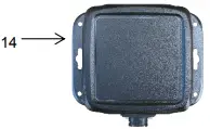
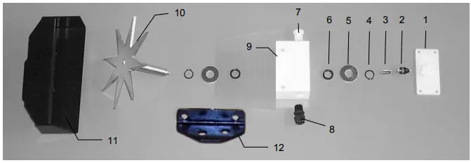
Parts Breakdown for 600SS Series Control and Harnesses
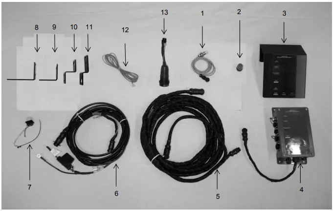
| Ref | Description | Part Number | Qty |
| 1 | End Of Bale Sensor | 006-7400 | 2 |
| 2 | Terminating Connector w green cap | 006-5650Z | 1 |
| 3 | DCP Shield/Cover | 001-5650X | 1 |
| 4 | DCP Main Control LS 600 AUTO | 006-6671SS | 1 |
| 5 | DCP Baler Harness 30 FT | 006-6650LS2(E) | 1 |
| 6 | DCP Tractor Harness | 006-6650TM(E) | 1 |
| 7 | Dust Plugs | 006-5651PLUGS | 1 |
| 8 | SC Bracket Inline SSQ | 001-4648SI | 1 |
| 9 | SMSQ End of Bale Bracket | 001-4648SS | 1 |
| 10 | EOB Bracket Inline SSQ | 001-4648SC | 1 |
| 11 | Round Baler End of Bale Bracket | 001-4648RB | 1 |
| 12 | Key Switch Wire | 006-5650K | 1 |
| 13 | Optional ISOBUS Tractor Plug (not included) | 006-6670A | 1 |
| 14 | iPad Integration Control | 030-6672C | 1 |
| NP | Y Splitter for EOB & Stroke Counter | 006-7400Y | 1 |
| NP | USB Cord | 006-6672USBC | 1 |
Star Wheels and Bale Rate Sensors
| Ref | Description | Part# | Qty | Ref | Description | Part# | Qty |
| 1 | Block cover | 006-4641B | 2 | 9 | Star wheel block | 006-4641D | 2 |
| 2 | Electronic swivel | 006-4642A | 2 | 10 | Star wheel sensor | 030-4641C | 2 |
| 3 | Swivel insert | w/ Ref # 10 | 2 | 11 | Twine guard – left | 001-4645 | 1 |
| 4 | Snap ring (per side) | 006-4641K | 2 | Twine guard – right (prox) | 001-4644 | 1 | |
| 5 | Washer (per side) | w/006-4641K | 2 | 12 | Prox Sensor Holder | 001-4644SS | 1 |
| 6 | Dust seal (per side) | w/006-4641K | 2 | ||||
| 7 | Plug fitting | 003-F38 | 2 | 1-10 | Star wheel assembly | 030-4642 | 2 |
| 8 | Wiring grommet | 008-0821A | 2 |
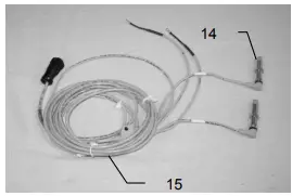
| Ref | Description | Part# | Qty |
| 14 | Bale rate sensor | 006-7303S | 2 |
| 15 | Moisture and bale rate harness | 006-7303HS(E) | 1 |
| Complete Assembly | 006-7202 |
Optional iPad Mini Mounting Kit (030-2014MK)
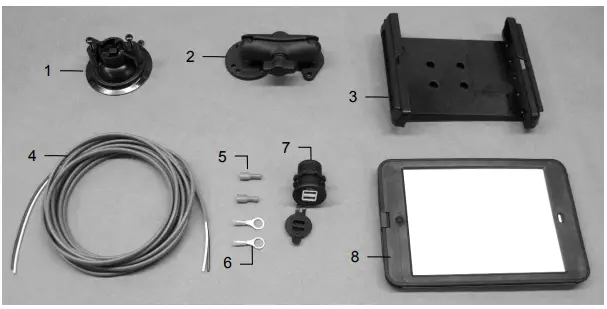
| Ref | Description | Part # | Qty |
| 1 | Suction cup mount | 001-2012SCM | 1 |
| 2 | Ram mount | 001-2012H | 1 |
| 3 | iPad Mini® spring load cradle (Mini 4) | 001-2012SLC | 1 |
| 4 | 16 gauge power wire | 006-4723P | 1 |
| 5 | Female spade connector | Hardware | 2 |
| 6 | Eye loop connector | Hardware | 2 |
| 7 | iPad Mini Charger 12V | 001-2012P | 1 |
| 8 | iPad Mini 4 case | 001-2012C4 | 1 |
| NP | 4 amp fuse | Hardware | 1 |
| Mounting Kit Assembly | 030-2014MK | ||
| (Includes All Parts) | |||
Installation Instructions
- Identify 12V power source for wires to connect.
a. Eye loops included if wiring directly to the battery is desired.
b. Test for key power source if preferred to have power to the USB shut off with the key. - Once power source is identified, cut wires to desired length.
- Crimp the two supplied quick connectors onto each the white and black wire.
- Remove the round locking plastic nut from USB plug before connecting the wires. Black (+) White (-).
- The wires will then be hooked to the designated terminals on the bottom of the USB plug
- Drill a 1 1/8” hole in the preferred mounting location. Be sure to clean any sharp edges after drilling.
- Feed the wires through the mounting hole.
- If using the round plastic nut to secure plug in place, slide the nut back over the wiring before connecting the wires to powered source.
- Connect the wires to the identified power source if easier to do so before tightening the plug into place.
- Tighten plug using either the round plastic nut or mounting plate and two screws, both options supplied.
- Once connected, hook a USB charging cord into the plug and connect a mobile device/tablet to ensure the plug is operating as you wish (key power working properly if necessary).
NOTE: This plug is not designed to charge two iPads. System damage could occur if this is attempted.
System will charge a mobile phone and iPad simultaneously without problem.
iPad mini is a trademark of Apple Inc., registered in the U.S. and other countries.
Optional iPad Display Kit (030-4670DK)
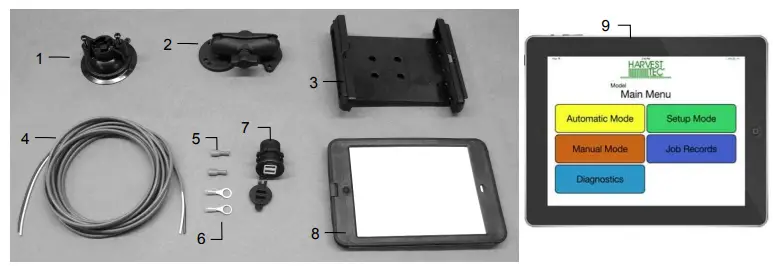
| Ref | Description | Part # | Qty | Ref | Description | Part # | Qty |
| 1 | Suction cup mount | 001-2012SCM | 1 | 7 | iPad Mini Charger 12V | 001-2012P | 1 |
| 2 | Ram mount | 001-2012H | 1 | 8 | iPad Mini 4 case | 001-2012C4 | 1 |
| 3 | iPad Mini® spring load cradle (Mini 4) | 001-2012SLC | 1 | 9 | iPad Mini 4 | 006-4670IP | 1 |
| 4 | 16 gauge power wire | 006-4723P | 1 | NP | 4 amp fuse | Hardware | 1 |
| 5 | Female spade connector | Hardware | 2 | ||||
| 6 | Eye loop connector | Hardware | 2 | Mounting Kit Assembly | 030-4670DK | ||
| (Includes All Parts) | |||||||
Installation Instructions
- Identify 12V power source for wires to connect.
a. Eye loops included if wiring directly to the battery is desired.
b. Test for key power source if preferred to have power to the USB shut off with the key. - Once power source is identified, cut wires to desired length.
- Crimp the two supplied quick connectors onto the white and black wire.
- Remove the round locking plastic nut from USB plug before connecting the wires. Black (+) White (-).
- The wires will then be hooked to the designated terminals on the bottom of the USB plug
- Drill a 1 1/8” hole in the preferred mounting location. Be sure to clean any sharp edges after drilling.
- Feed the wires through the mounting hole.
- If using the round plastic nut to secure plug in place, slide the nut back over the wiring before connecting the wires to powered source.
- Connect the wires to the identified power source if easier to do so before tightening the plug into place.
- Tighten plug using either the round plastic nut or mounting plate and two screws, both options supplied.
- Once connected, hook a USB charging cord into the plug and connect a mobile device/tablet to ensure the plug is operating as you wish (key power working properly if necessary).
NOTE: This plug is not designed to charge two iPads. System damage could occur if this is attempted. System will charge a mobile phone and iPad simultaneously without problem.
iPad mini is a trademark of Apple Inc., registered in the U.S. and other countries.
Harvest Tec LLC. Warranty and Liability Agreement
Harvest Tec, LLC. will repair or replace components that are found to be defective within 12 months from the date of manufacture. Under no circumstances does this warranty cover any components which in the opinion of Harvest Tec, LLC. have been subjected to negligent use, misuse, alteration, accident, or if repairs have been made with parts other than those manufactured and obtainable from Harvest Tec, LLC.
Our obligation under this warranty is limited to repairing or replacing free of charge to the original purchaser any part that in our judgment shows evidence of defective or improper workmanship, provided the part is returned to Harvest Tec, LLC. within 30 days of the failure. If it is determined that a non-Harvest Tec branded hay preservative has been used inside the Harvest Tec applicator system where the failure occurred, then Harvest Tec reserves the right to deny the warranty request at their discretion. Parts must be returned through the selling dealer and distributor, transportation charges prepaid.
This warranty shall not be interpreted to render Harvest Tec, LLC. liable for injury or damages of any kind, direct, consequential, or contingent, to persons or property. Furthermore, this warranty does not extend to loss of crop, losses caused by delays or any expense prospective profits or for any other reason. Harvest Tec, LLC. shall not be liable for any recovery greater in amount than the cost or repair of defects in workmanship.
There are no warranties, either expressed or implied, of merchantability or fitness for particular purpose intended or fitness for any other reason.
This warranty cannot guarantee that existing conditions beyond the control of Harvest Tec, LLC. will not affect our ability to obtain materials or manufacture necessary replacement parts.
Harvest Tec, LLC. reserves the right to make design changes, improve design, or change specifications, at any time without any contingent obligation to purchasers of machines and parts previously sold.
HARVEST TEC, LLC.
P.O. BOX 63
2821 HARVEY STREET
HUDSON, WI 54016
PHONE: 715-386-9100
1-800-635-7468
FAX: 715-381-1792
Email: [email protected]
DECLARATION OF INCORPORATION

MANUFACTURER:
Harvest Tec LLC.
2821 Harvey St.
P.O. Box 63
Hudson, WI 54016, U.S.A.
REPRESENTATIVE ESTABLISHED IN COMMUNITY:
Profitable Farming Company
Middle Barlington, Roborough
Winkleigh, Devon, EX19 8AG
ENGLAND
The person above certifies and declares that:
VIRTUAL MACHINE: Equipment mounted on a farm press and for the application of innoculants onto forage crops.
MODEL: 600SS-INST-17-Imp&Metric BRAND: Harvest Tec
SERIAL NUMBER:
This application preservatives for hay Harvest Tec system meets the Directive 2006/42/EC of the European Parliment and the Council of 17 May 2006 and other applicable European Directives including Directive 2004/108/EC on the Electromagnetic compatability.
The application of preservatives for hay Harvest Tec system will be turned on after being installed on a farm press has been declard in conformity with the Machinery Directive.
Person in the community authorized to provide information on the partly completed machinery and making this statement:
Richard Snell, President, Profitable Farming Company Signed on May 21, 2011: Middle Barlington, Roborough Winkleigh, Devon, EX19 8AG
ENGLAND


