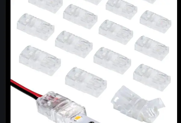
Armacost WireGrip Connectors
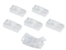
WireGrip Connectors
IMPORTANT: These instructions cover wire and splice connector models for both single color and RGB color changing LED tape lighting.
WireGrip Connectors
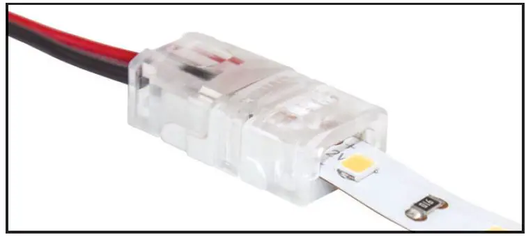
Used to join 2-conductor wire to single color LED lighting or 4-conductor wire to RGB LED lighting.
WireGrip Splice Connectors
WireGrip Splice Connectors are used to join two strips, creating a continuous run of LED lighting. Skip to step 6 in these instructions.
For instructional purposes, photos and illustrations shown will relate to both single color and RGB connectors.
- No soldering or special tools required. WireGrip Connectors allow you to easily add low voltage power wire leads to your LED tape lighting
- Uses a clamp-down mechanism with insulation-piercing metal pins that make secure and reliable connections without soldering, no stripping of wires is needed
- Works with 22, 20, and 18AWG gauge wire, however some wire types with thicker than standard insulation may not work properly –always test a sample wire fi first
- To view an online video tutorial visit armacostlighting.com/WireGrip
Tools you may need
- Scissors
- Small fl at-head screwdriver
- Pliers (fi ne tip is recommended)
- Heat shrink tubing (for outdoor installations)
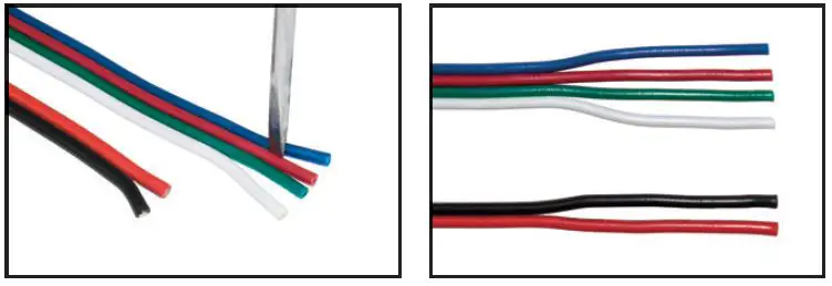
Prep the Wires
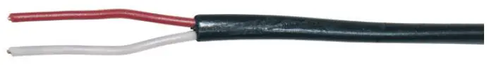
If your wire has an outer jacket, remove a portion to expose individual wires as shown.
If your wire is the fl at ribbon wire type separate the ends of wires with a fl athead screwdriver or razor knife to about 1 inch. Do not strip wire bare.
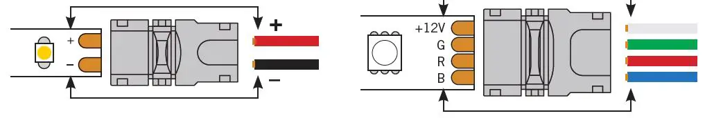
Plan your wire layout, maintain polarity
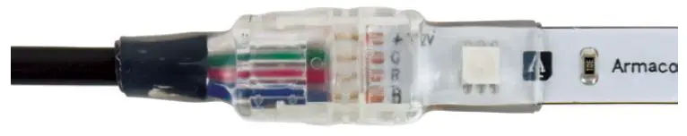
Check the polarity of your tape. Use the + and – (single color lighting) or +12V/G/R/B (RGB color-changing) markings printed on the tape light as a guide to maintain the same polarity with your power supply or color controller low voltage outputs.
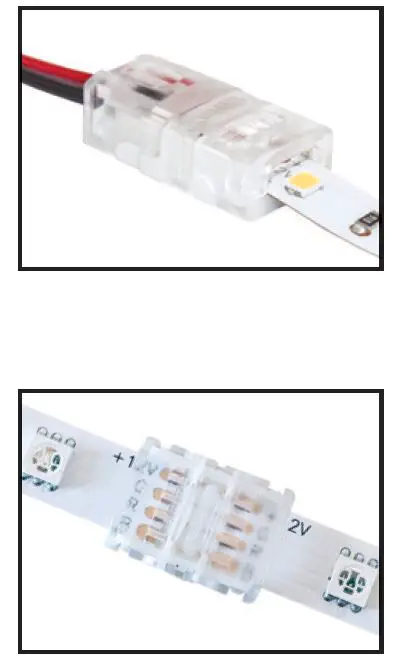
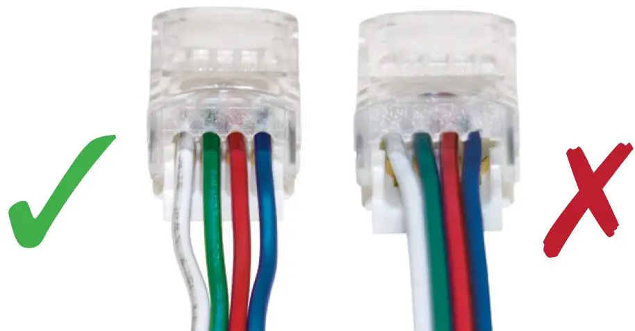
Insert wires into the Wire Grip Connector
The wires go in the grooved side of the connector. Be sure the individual wires seat themselves in the receiving grooves.
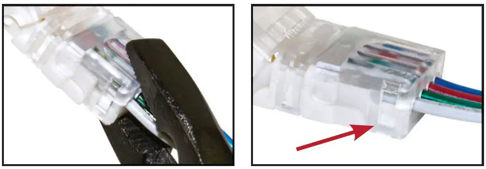
Clamp the connector wire cover closed
Use pliers to apply gentle pressure evenly across the pressure door. Be sure that the small locks on both sides are fully engaged.
Prep your LED tape lighting
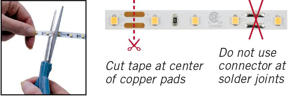
Cut your LED tape to length. Cut on bare copper, do not use factory solder joints.
Insert the LED tape into the connector
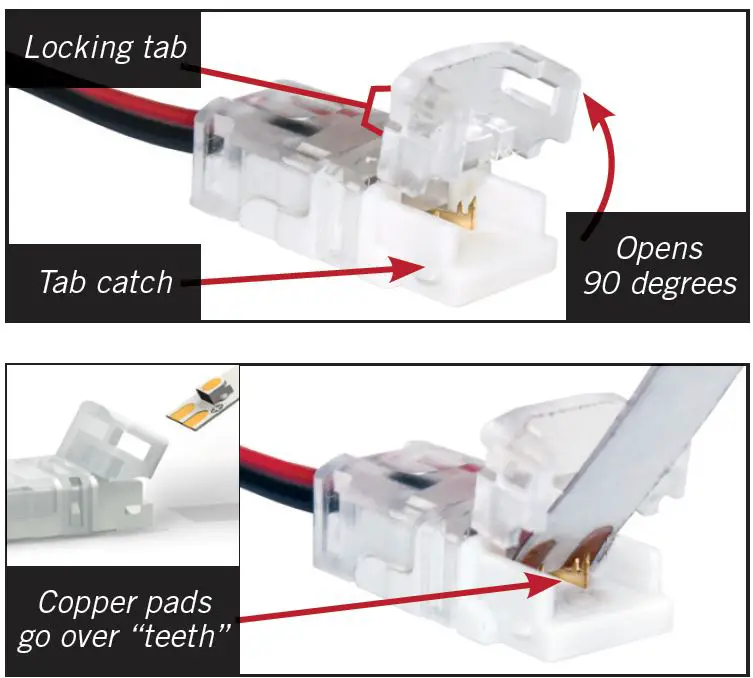
First: open the short door on the connector 90 degrees. Remove 1 in. of 3M paper backing and insert LED tape face up.
IMPORTANT! Position tape light copper pads on top of the connector’s copper teeth as shown.
Follow the same basic instructions when using WireGrip Splice Connectors. Be sure to maintain polarity between LED strips.
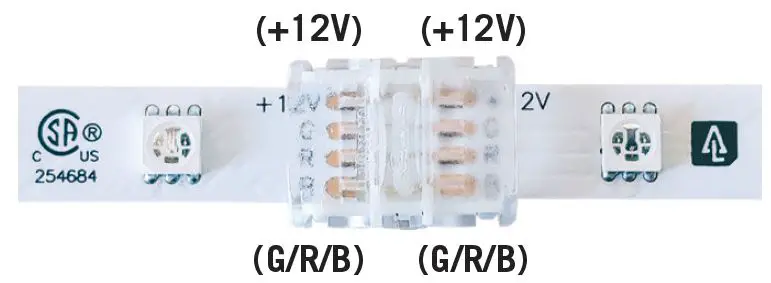
If the +12V/G/R/B marks do not line up, fl ip the tape strip and use the opposite end for proper +12V/G/R/B alignment.
Close and lock down the tape light cover door
Using finger pressure only, close the tape pressure door. Do NOT use pliers on this side of the connector. Check mechanical and electrical connections on both sides by gently pulling up on the tape lighting and wiring, one at a time. The locks on either side of the connector should stay secure. Apply power before installation to make sure your lights turn on and RGB colors are correct.
WireGrip Connectors can be reused if necessary. Use a small fl athead screwdriver to open up the locking tabs on either side of the cover door. The cover door will break if fl exed excessively. Avoid rough use.
IMPORTANT: If you are using WireGrip Connectors with outdoor rated LED tape lighting, all connectors must be sealed with adhesive lined heat-shrink tubing as shown.
Allow at least 1 in. overage of heat shrink tubing to make a water tight seal with the cable and tape light.
Troubleshooting
| Problem | Solution |
| Tape lighting does not power up | Check your polarity and make sure each wire goes to the appropriate copper pad Make sure both the wires and tape lighting are fully seated inside the connector and the pressure pad doors are fully closed and latched on both sides |
| Cover door will not close | Make sure wires are inserted in the correct side, are aligned with the grooves, and are sufficiently separated Use even pressure to close the door in the center of the connector If the locks on the sides are broken, discard that connector |
| RGB color lighting is mismatched | Check your polarity and RGB alignment |
armacostlighting.com
© 2018-21 Armacost Lighting. All rights reserved.


