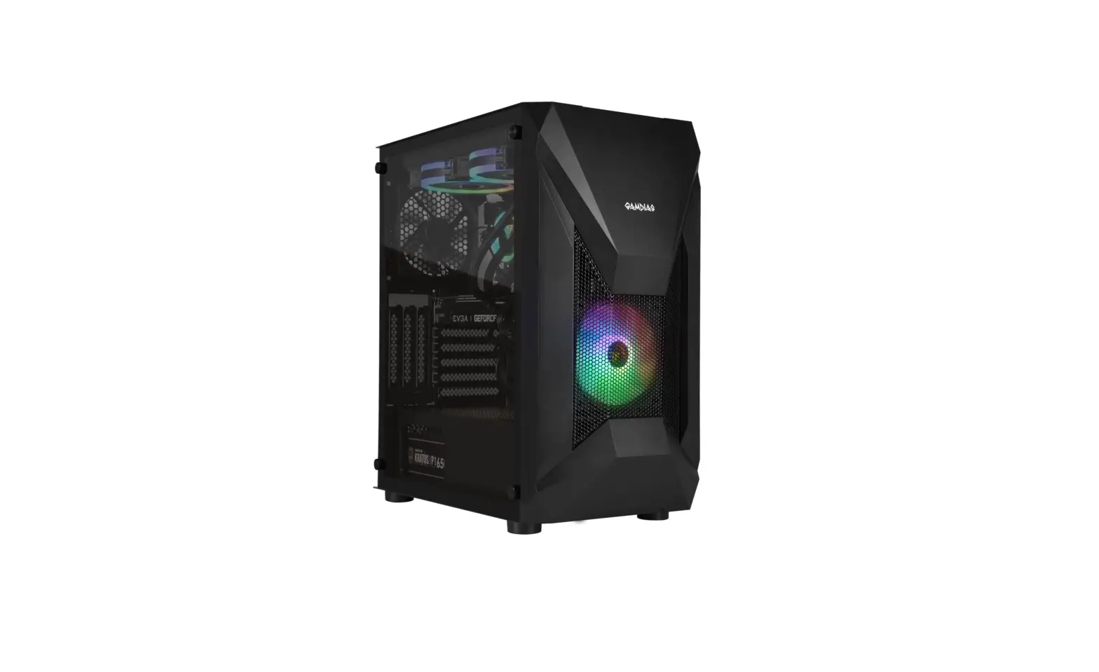
GAMDIAS Athena E1 Elite Micro Tower Gaming Case Installation Guide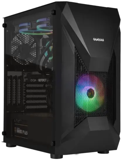
SPECIFICATIONS
SERIES: MESH Strips Series
Product Name: ATHENA E1 Elite
Case Type: MID Tower
Dimension (L x W x H): 420 x 230 x 460 mm 16.5 x 9 x 18.1 inch
Chassis Dimension (L x W x H): 350 x 230 x 445 mm 13.7 x 9 x 17.5 inch
Motherboard Support: ATX, Micro-ATX,Mini-ITX
Expansion Slots: 7+3
Material: SPCC , ABS , Tempered glass
Window: Left
Radiator Support: Top: 280 mm, 240mm Rear: 140 mm, 120mm
Fan Support: Top: 2 x 120mm , 2 x 140mm Front: 1 x 120mm , 1 x 140 mm Rear: 1 x 120mm, 1 x 140mm
Pre-installed Fans: Front: 1 x 120mm ARGB Fans Rear: 1 x 120mm Fan
Pre-installed Control BOX: NO
Motherboard Sync: 5V 3-Pin Addressable Header
Drive Bays: 2 x 3.5″ or 1 x 2.5″+1 x 3.5″(HDD Cage) 3 x 2.5″
Clearance: CPU cooler height limitation: 190mm VGA length limitation: 340mm PSU length limitation: 180mm
I/O Port: USB 3.0 x1, USB 2.0 x2, HD Audio x1, LED Control x1
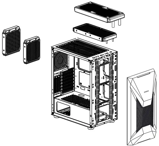
EXPLODED VIEW & PARTS
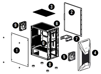
PARTS
Chassis Body
- Tempered Glass Side Panel
- Right Side Panel
- Top Dust Filters
- Front Panel
- 120MM ARGB FAN
- IO Port
- HDD Cage
- Rubber Foot
- 120 MM Fan
ACCESSORY
| Figure | Parts Name | Qty | Used for |
| Stand-off 4.75 x 9.5 x 6.5mm | 3 | Motherboard | |
| Screw #6 x 6 mm | 6 | PSU |
| Screw #6 x 5 mm | 9 | HDD |
| Screw M3 x 5 mm | 18 | 2.5″ HDD/Motherboard/ODD |
| CableTie | 5 | Cable Management |
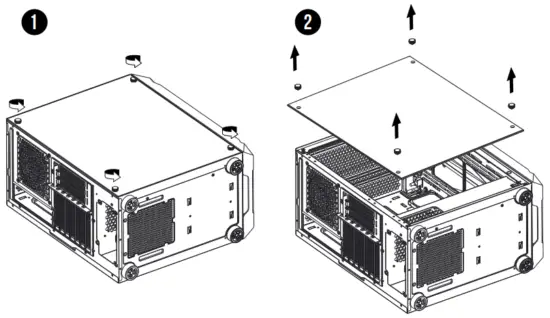
SIDE PANEL REMOVAL
Remove the side panel
MOTHERBOARD INSTALLATION
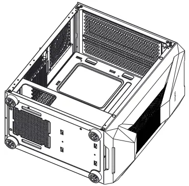
Lay down the chassis Install the motherboard in proper location and secure it with screws
PSU INSTALLATION
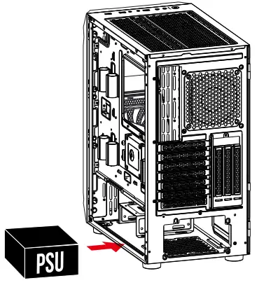
Place the PSU in proper location
3.5″ 2.5″ HDD INSTALLATION
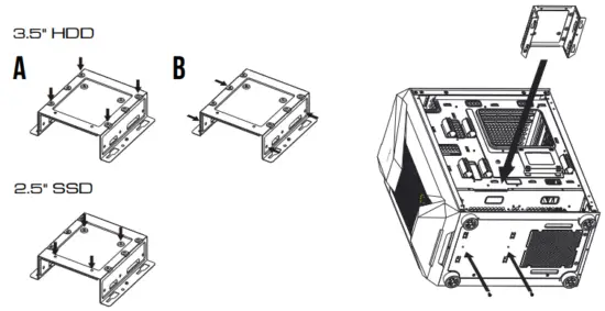
A. 3.5″ HDD
Align the HDD into the mounting holes and screw in.
B. 2.5″ SSD
Align the SSD into the mounting holes and screw in.
AIR COOLING COMPATIBILITY
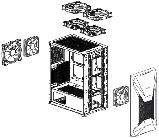
Top 2 x 120mm or 2 x 140mm
Front 1 x 120mm or 1 x 140mm
Rear 1 x 120mm or 1 x 140mm
RADIATOR COMPATIBILITY
Top 280 mm or 240 mm
Rear 140 mm or 120 mm
I/O PORTS
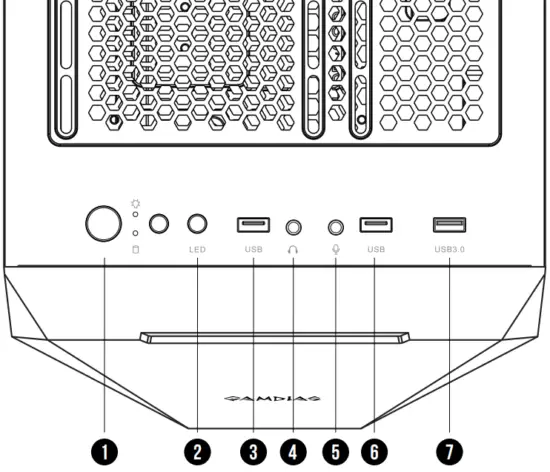
- Power Button
- Fan LED Control
- USB 2.0
- Headphone
- Mic
- USB 2.0
- USB 3.0
Sync With Motherboard : Press and Hold the Fan LED Control Button for 3 Seconds.
I/O CONNECTORS
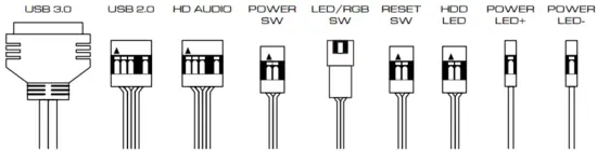
See your motherboard’s manual for front panel header locations and pin-outs.


