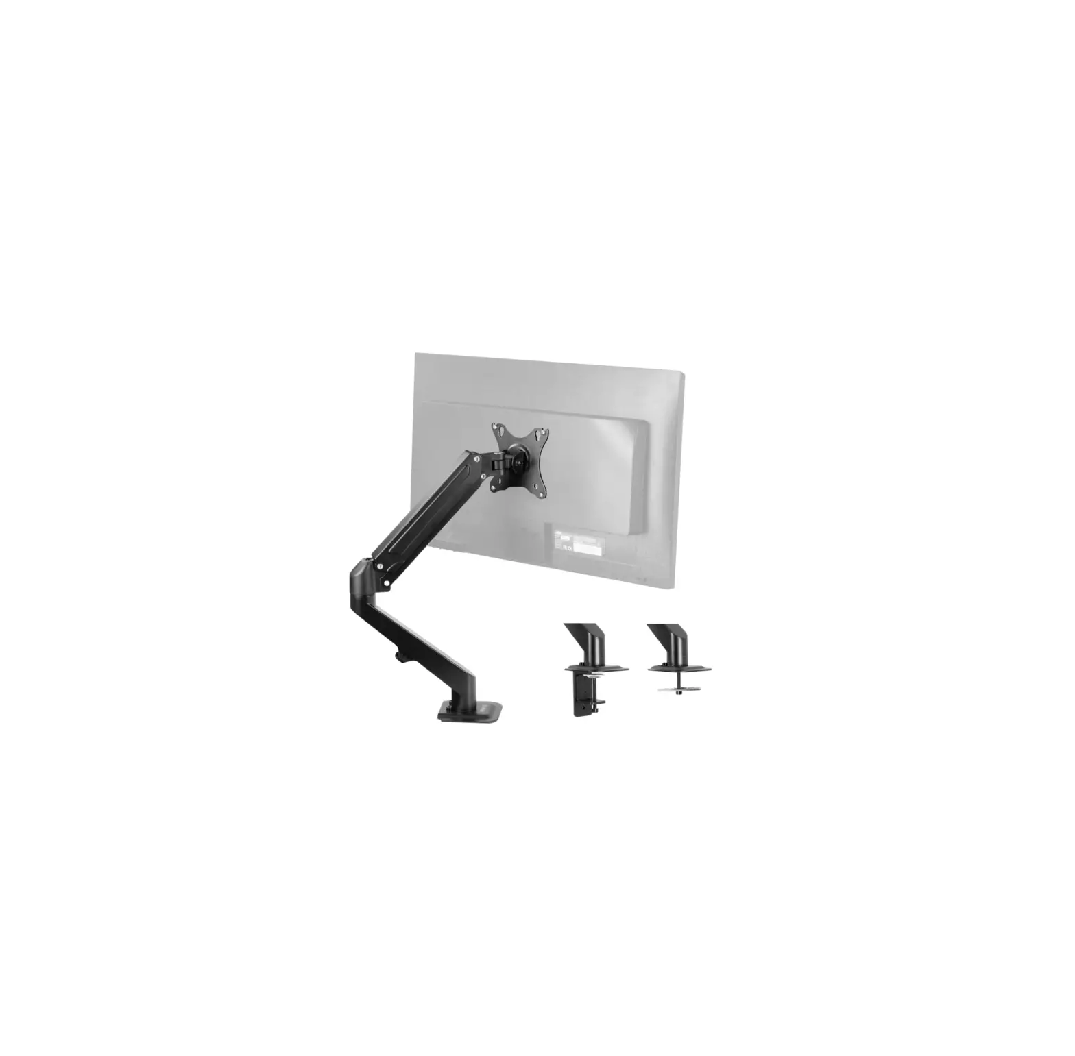
VIVO STAND-V101G1U Pneumatic Arm Single Monitor Desk Mount
![]() WARNING!
WARNING!
If you do not understand these directions, or if you have any doubts about the safety of the installation, please call a qualified technician. Check carefully to make sure there are no missing or defective parts. Improper installation may cause damage or serious injury. Do not use this product for any purpose that is not explicitly specified in this manual. Do not exceed weight capacity. We cannot be liable for damage or injury caused by improper mounting, incorrect assembly or inappropriate use.
![]() TIPOVER WARNING
TIPOVER WARNING
SERIOUS OR FATAL CRUSHING INJURIES CAN OCCUR FROM TIPOVER. TO HELP PREVENT TIPOVER:
- NEVER ALLOW CHILDREN TO CLIMB, STAND, HANG, OR PLAY ON ANY PART OF MONITOR OR STAND.
- USE TIPOVER RESTRAINT OR ANCHOR STAND TO WALL
USE OF TIPOVER RESTRAINTS MAY ONLY REDUCE, BUT NOT ELIMINATE RISK OF TIPOVER.
![]() WARNING: CHOKING HAZARD
WARNING: CHOKING HAZARD
SMALL PARTS – NOT FOR CHILDREN UNDER 3 YEARS. ADULT SUPERVISION IS REQUIRED.
PACKAGE CONTENTS
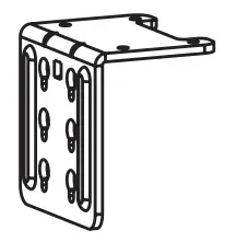
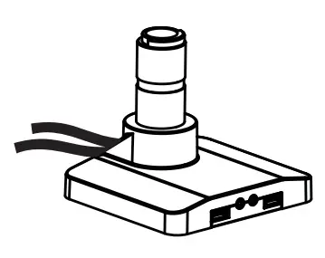 | A (x1) Base | 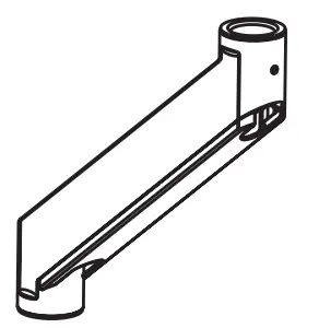 | B (x1) Lower Arm |
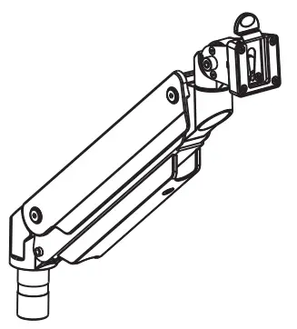 | C (x1) Gas Spring Arm | 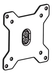 | D (x1) VESA Plate |
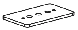 | E (x1) Clamp Plate | 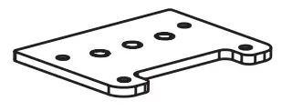 | F (x1) Grommet Plate |
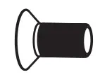
 | G (x1) Soft Pad | 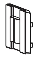 | H (x1) Cover |
 | I (x1) Clamp Brace | 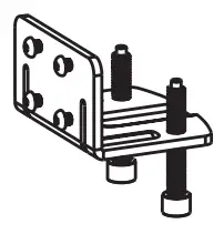 | J (x1) Clamp |
 | S-A (x4) M6x12mm Screw | 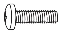 | M-A (x4) M4x12mm Screw |
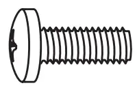 | M-B (x4) M5x12mm Screw |  | M-C (x4) M5 Washer |
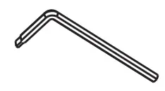 | T-A (x1) 3mm Allen Wrench | | T-B (x1) 4mm Allen Wrench |
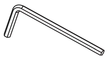 | T-C (x1) 6mm Allen Wrench |
NOTE: SOME HARDWARE INCLUDED MAY NOT BE USED
TOOLS NEEDED
Phillips Screwdriver
 | DO NOT EXCEED WEIGHT CAPACITY. Failure to do so may result in serious injury. |
ASSEMBLY STEPS
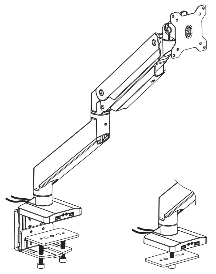
STEP 1 (Option A)
Clamp Installation
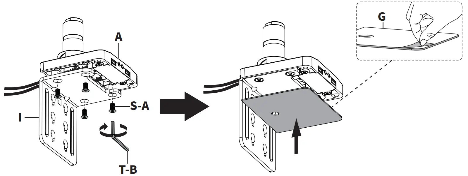
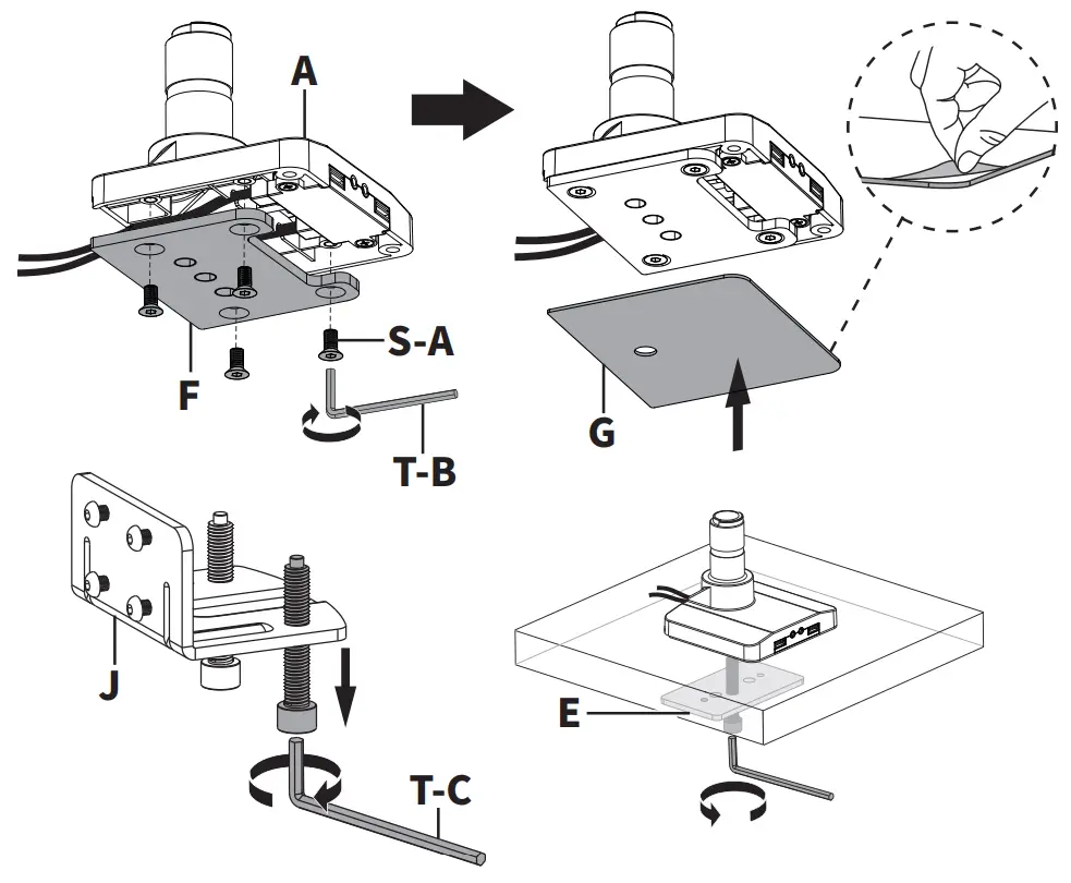
Attach Clamp Brace (I) to Base (A) using M6x12mm Screws (S-A) and 4mm Allen Wrench (T-B). Apply Soft Pad (G) to underside of Base (A).
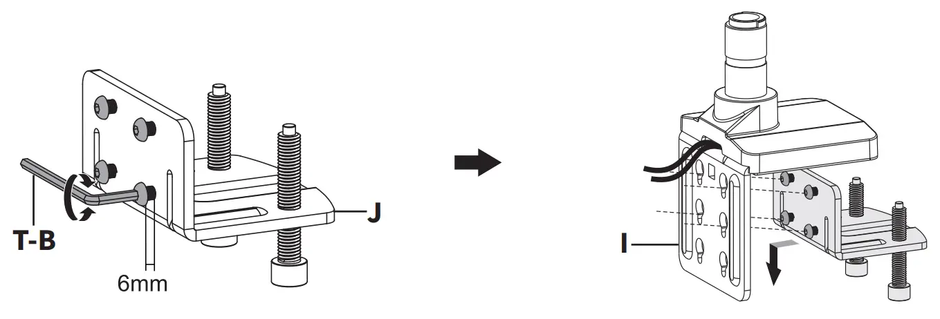
Loosen screws on the back of Clamp (J), leaving 6mm of thread exposed. Assemble Clamp (J) to Clamp Brace (I) and retighten screws using 4mm Allen Wrench (T-B). Place Clamp Plate (E) on top of clamp bolts.
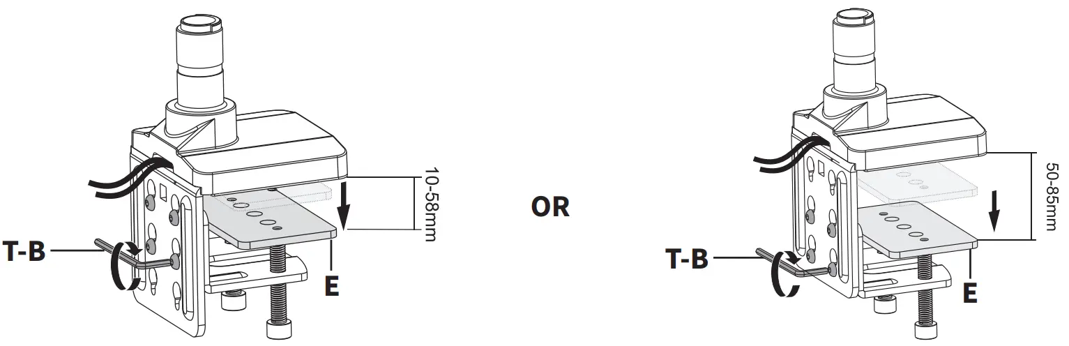
For a Desk Thickness of 3/8” – 2-1/2” (10mm – 58mm), hang Clamp (J) in top 4 slots of Clamp Brace (I).
For a Desk Thickness of 2” – 3-3/8” (50mm – 85mm), hang Clamp (J) in bottom 4 slots of Clamp Brace (I).
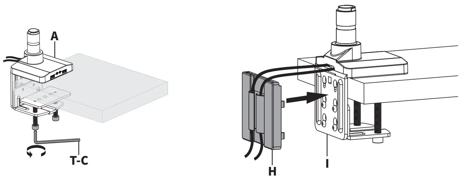
Position Base (A) on desktop and tighten clamp bolts evenly using 6mm Allen Wrench (T-C). Attach Cover (H) to back of Clamp Brace (I).
STEP 1 (Option B)
Grommet Base Installation
Attach Grommet Plate (F) to Base (A) using M6x12mm Screws (S-A) and tighten with 4mm Allen Wrench (T-B). Apply Soft Pad (G) to underside of Base (A). Position Base (A) over grommet hole in desktop, or drill a 3/8” (10mm) hole through the desk for installation. Remove clamp bolt from Clamp (J) using 6mm Allen Wrench (T-C). Insert clamp bolt with Clamp Plate (E) up through the underside of the desk and tighten to Base (A) using the 6mm Allen Wrench (T-C).
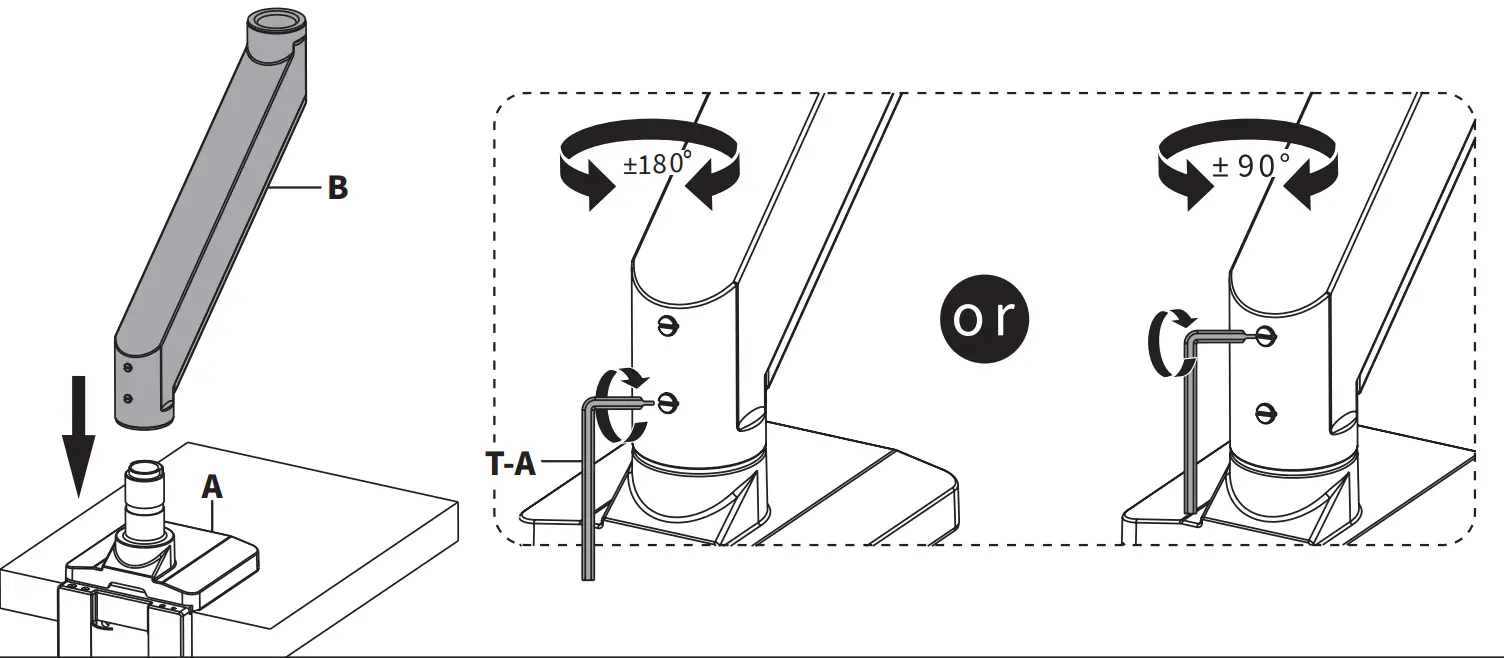
STEP 2
Place Lower Arm (B) on top of Base (A), and secure by turning the lower screw in back with 3mm Allen Wrench (T-A). Optionally, also tighten the upper screw to restrict swivel movement to +/-90 degrees.
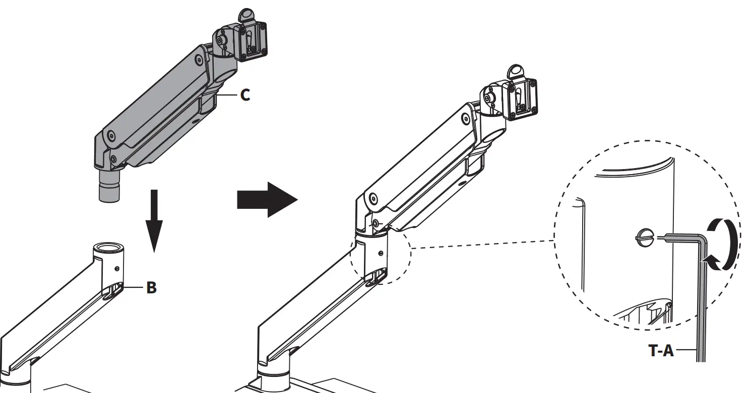
STEP 3
Assemble Gas Spring Arm (C) to Lower Arm (B), and secure by tightening the set screw in Lower Arm (B) using 3mm Allen Wrench (T-A).
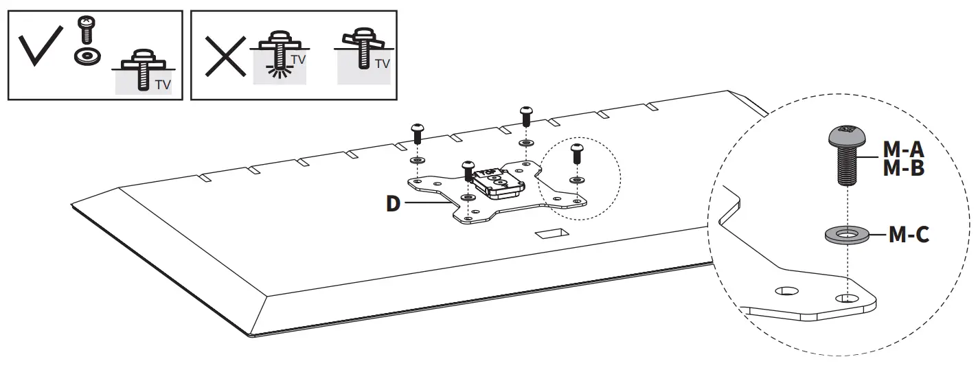
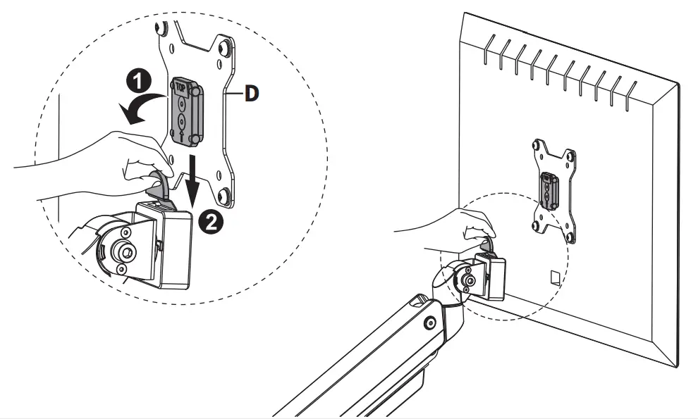
STEP 4
Install VESA Plate (D) to monitor using M4x12mm Screws (M-A) or M5x12mm Screws (M-B) with M5 Washers (M-C), making sure the arrow on VESA Plate (D) is pointing up.
STEP 5
Pull back the release lever on the support bracket, then place the monitor with VESA Plate (D) into the support.
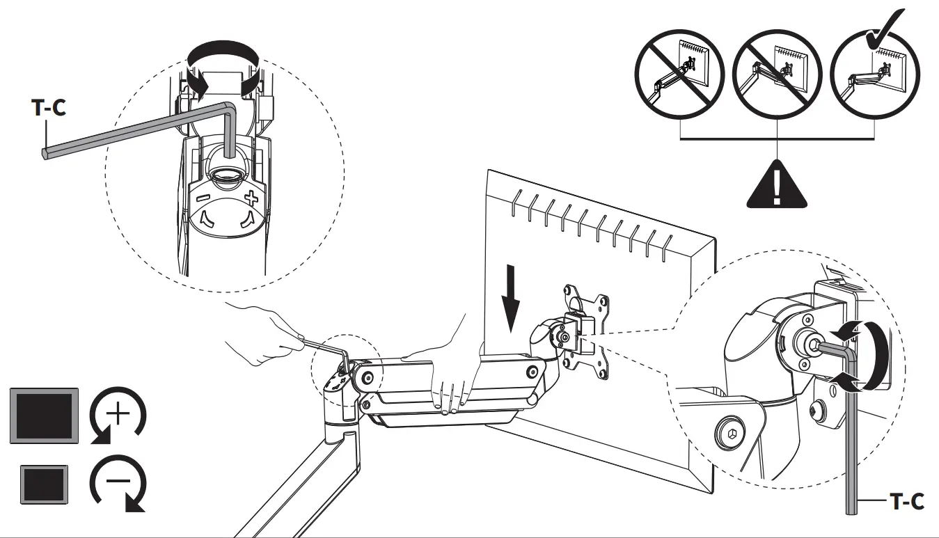
STEP 6
If needed, adjust gas spring arm to support the monitor using the 6mm Allen Wench (T-C). Turn the screw in back clockwise to increase support, and counter-clockwise to decrease. Adjust the tilt joint using 6mm Allen Wrench (T-C).
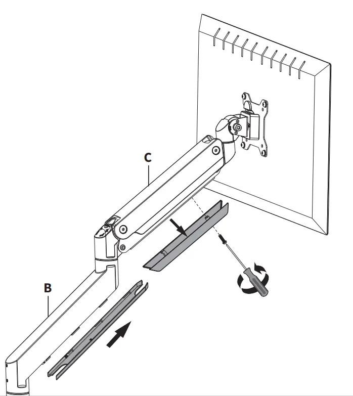
STEP 7
Remove cable cover on Gas Spring Arm (C) using a Phillips screwdriver. Slide cable cover on Lower Arm (B) forward to remove.
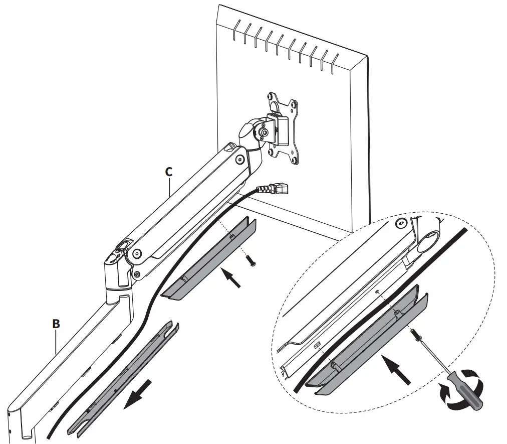
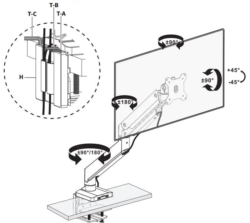
STEP 8
Organize cables, then reinstall cable covers to Gas Spring Arm (C) and Lower Arm (B).
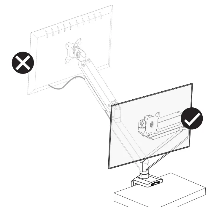
STEP 9
For safety, please do not extend the monitor behind the desk. This may cause instability and tip the desk over.
STEP 10
Adjust as desired. Store Allen Wrenches (T-A, T-B, T-C) in Cover (H) for future adjustments.
![]() Love your new VIVO setup and want to share?
Love your new VIVO setup and want to share?
Tag us in your photo! @vivo_us
SKU: STAND-V101G1U
 | Scan the QR code with your mobile device or follow the link for helpful videos and specifications related to this product. Instruction Manual |
Customer Support
GET IN TOUCH Open Monday – Friday 7:00am – 7:00pm CST,
our dedicated support team can offer immediate assistance with rapid response times. If any parts are received damaged or defective, please contact us. We are happy to replace parts to ensure you have a fully functioning product.
 | www.vivo-us.com Chat live with an agent! | AVG. RESOLUTION TIME (within office hrs): < 15 M |
 | 309-278-5303 | AVG. RESOLUTION TIME (within office hrs): 5M 4S |
 | [email protected] | AVG. RESPONSE TIME (within office hrs): 1HR 8M
|
FOR MORE VIVO PRODUCTS, CHECK OUT OUR WEBSITE AT: www.vivo-us.com


