
IMMERGAS 3.015245 Modulating Room Thermostat Kit User Manual
MODULATING ROOM THERMOSTAT KIT
CODE 3.015245
GENERAL WARNINGS.
All products are protected with suitable transport packaging.
The material must be stored in dry environments and protected against weathering.
This instruction manual provides technical information for installing the kit. As for the other issues related to kit installation (e.g. safety in the work site, environment protection, injury prevention), it is necessary to comply with the provisions specified in the regulations in force and principles of good practice.
Improper installation or assembly of the appliance and/or components, accessories, kit and devices can cause unexpected problems to people, animals and objects. Read the instructions provided with the product carefully to ensure a proper installation.
Installation and maintenance must be performed in compliance with the regulations in force, according to the manufacturer’s instructions and by authorised professionally qualified staff, intending staff with specific technical skills in the plant sector, as envisioned by the Law.
RECOMMENDED INSTALLATION SEAT.
The room thermostat kit must be installed away from heat sources, at a height of approx. 1.20-1.50 m and in a suitable position for correctly measuring the temperature.
The room thermostat must not be installed:
- in places exposed to direct sunlight;
- in the vicinity of appliances that produce heat, such as TV sets, refrigerators, wall lamps, radiators, etc.;
- on walls behind which there are heating pipes or flues;
- on external walls;
- in corners or recesses, on shelves or behind curtains (insufficient air circulation);
- near entrance doors of non-heated rooms (influence of outside cold);
- on non-insulated fitted outlets (influence of outside cold due to flue effect of installation pipes).
Kit assembly.
Remove the front cover and fix the room thermostat in the required place with the screws and plugs supplied. Pass the data bus cable necessary for electrical connection through the special rear access.
ELECTRICAL CONNECTION.
To carry out the electrical connections do not operate with the main regulator powered, and respect the polarities by referring to the electrical connections given in the zone regulator instruction handbook. The electrical connection must be made to the special bipolar terminal board (see fig. 1).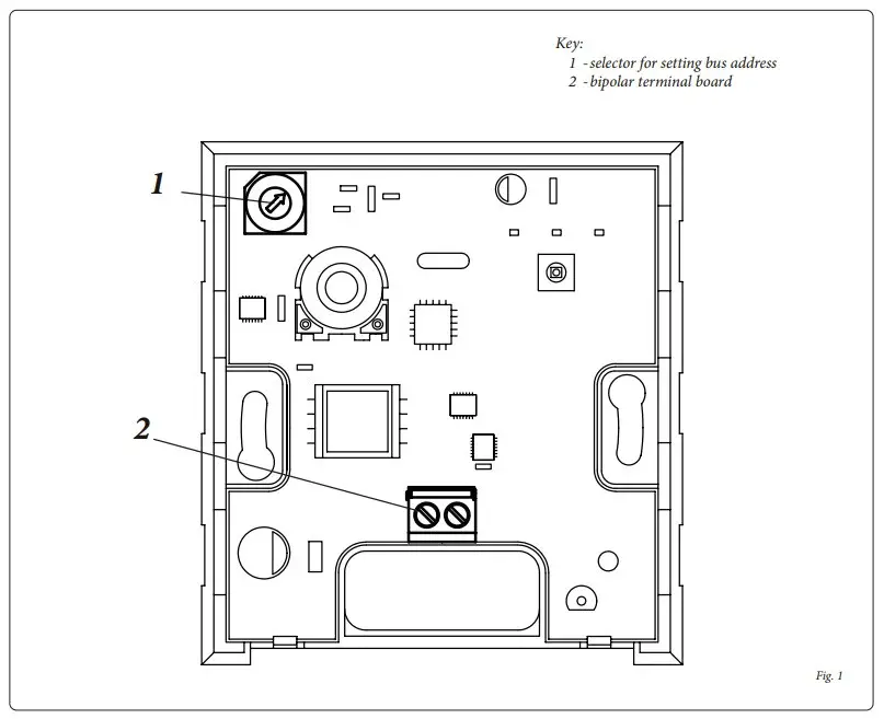
Recommended connection cable: J-Y (ST) Y 2x2x0.6.
Caution: Do not invert terminals A and B.
After connecting the data bus cable to the terminal board and setting the thermostat bus address (see table “Setting BUS address”), refit the front cover.
The modulating room thermostat allows a heating circuit to be adjusted independently of the others.
MAIN FUNCTIONS:
- Room temperature measurement (temperature sensor). The sensor incorporated in the thermostat reads the temperature in the room where it is installed and sends the value to the boiler via the bipolar BUS data line.
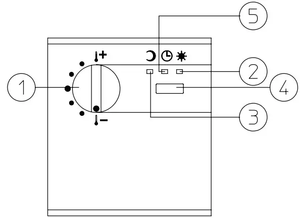
- Function mode switch (4) (automatic function (5) – permanent daytime temperature (2) – permanent reduced temperature (3).
The function mode can be selected by pressing the button (4) (the button must be pressed for about 2-3 seconds). The selected mode is displayed by the relative LED lighting up
![]() Automatic operation
Automatic operation
The heating circuit is regulated according to the time program entered in the main regulator
 Permanent daytime temperature
The heating circuit is regulated according to the daytime room temperature entered in
the main regulator.
![]() Permanent reduced temperature
Permanent reduced temperature
The heating circuit is regulated according to the reduced room temperature entered in the main regulator.
Required temperature adjustment.
The required temperature for the function mode selected can be modified with knob (1). By turning the knob it is possible to change the room temperature set in the main regulator within a range of +/- 6°C.
Turn clockwise to increase the temperature.
Turn anticlockwise to decrease the temperature.
SUPPLEMENTARY FUNCTIONS
The supplementary functions PARTY, ABSENT, HOLIDAYS, SUMMER and STANDBY are adjusted exclusively by the main regulator, but any insertion made can be displayed by the thermostat as described below.
| Function | Room thermostat |
| PARTY | LEDflashing |
| ABSENT | LED |
| HOLIDAYS | LED |
| SUMMER | All LEDs On |
| STANDBY | All LEDs On |
DISPLAY OF FAULTS / MALFUNCTIONS
| Fault/Malfunction | Led | Led | Led |
| Ignition phase / after apower failure | flashesbriefly | flashesbriefly | flashesbriefly |
| BUS address settingerror | flashing | on | on |
| Fault on BUS line / linenot present | on | flashing | on |
BUS ADDRESS SETTING
To enable communication between thermostat and main regulator the appropriate BUS address must be set.
The BUS address is set by means of the code selector located inside the thermostat (see fig. 1) according to the following table:
| Room thermostat | Main regulator | Heating circuit | |
| BUSaddress | No. | BUSaddress | |
| 1 | 1 | 10 | Direct heating circuit |
| 2 | 1 | 10 | Mixed heating circuit 1 |
| 3 | 1 | 10 | Mixed heating circuit 2 |
| 4 | 2 | 20 | Direct heating circuit |
| 5 | 2 | 20 | Mixed heating circuit 1 |
| 6 | 2 | 20 | Mixed heating circuit 2 |
| 7 | 3 | 30 | Direct heating circuit |
| 8 | 3 | 30 | Mixed heating circuit 1 |
| 9 | 3 | 30 | Mixed heating circuit 2 |
| A | 4 | 40 | Direct heating circuit |
| B | 4 | 40 | Mixed heating circuit 1 |
| C | 4 | 40 | Mixed heating circuit 2 |
| D | 5 | 50 | Direct heating circuit |
| E | 5 | 50 | Mixed heating circuit 1 |
| F | 5 | 50 | Mixed heating circuit 2 |
| 0 | available | available | |
IMPORTANT
Not more than one room thermostat can be set with the same BUS address. Data transmission errors are inevitable and can cause wrong functioning of thermoregulation (see Display faults/ malfunctions – BUS address setting error).
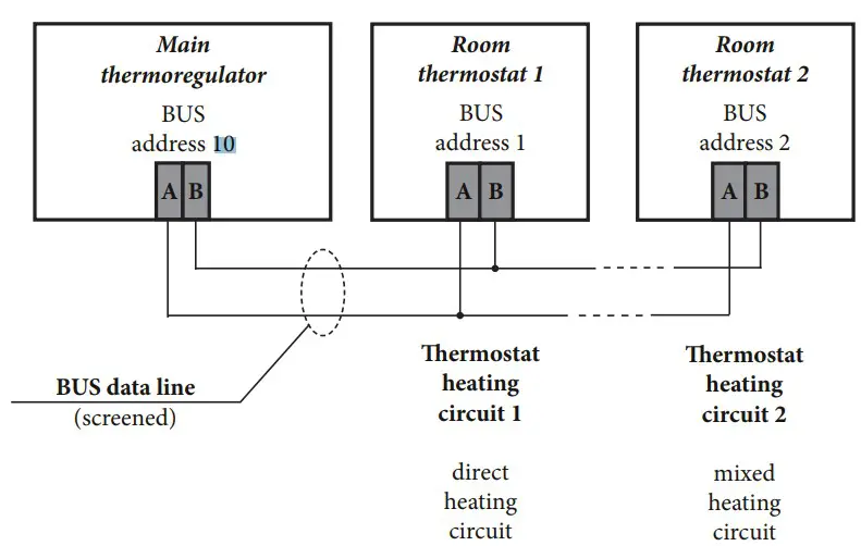
Installation example of one main regulator + 2 modulating room thermostats
PRODUCT SPECIFICATIONS.
In accordance with Regulation 811/2013 the temperature control device class is:
| Class | Contribution to the environmental heating seasonal energy efficiency | Description |
| V | +3% | Modulating Environ- ment Thermostat Kit |
| VI | +4% | Modulating Environment Thermostat Kit coupled to outer sensor |


