Rheem RP14AZ Endeavor Line Classic Series iM Heat Pumps Instruction Manua
Features and Benefits
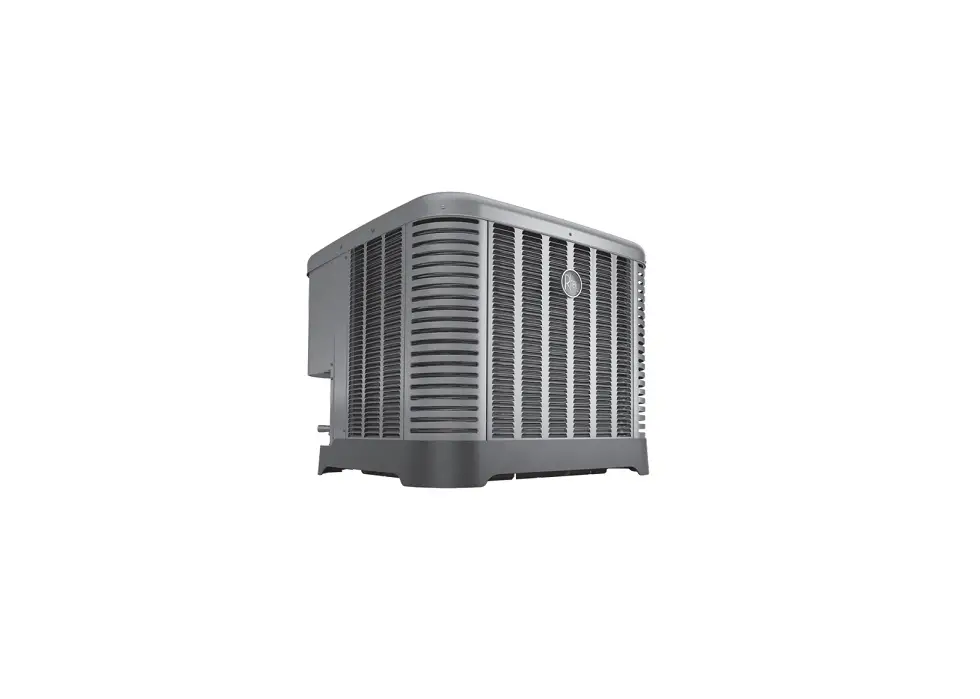
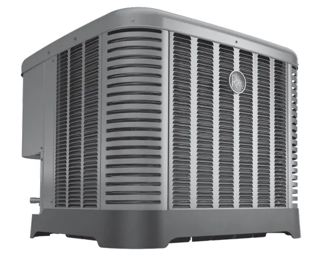
- Swept Wing Fan Technology1: Features quieter operation and improved unit acoustics
- Two-Stage Scroll Compressor2: Features two speeds (high and low) of cooling and heating, providing more precise
temperature control, lower humidity and greater efficiency when compared to single stage compressors
- Inverted Reversing Valve: Allows for faster heat transfer with gravity assist shifting and reduced joint stress for increased reliability
- PlusOne® Expanded Valve Space: 3 – 4 in. – 5 in. service valve space—provides a minimum working area of 27-square inches for easier access
- PlusOne® Triple Service Access: 15 in. wide, industry leading corner service access, two fastener, removeable corner and individual louver panels—makes repairs easier and faster
Heat Pumps
| R | P | 14 | A | Z | 18 | A | J | 1 | N | A |
| Brand | Product Category | SEER2 | Region | Refrigerant | Capacity | Major Series | Voltage | Type | Controls | Minor Series |
| R – Rheem | P – Heat Pump | 14 – 14.3 SEER2 | A – All Regions | Z – R-410A | 18 – 18,000 [5.28 kW] 24 – 24,000 [7.03 kW] 30 – 30,000 [8.79 kW] 36 – 36,000 [10.55 kW] 42 – 42,000 [12.31 kW] 48 – 48,000 [14.07 kW] 60 – 60,000 [17.58 kW] | A – 1st Design | J – 208/230/1/60 | 1 – 1-Stage 2 – 2-Stage | N – Non-Comm. | A – 1st Design |
Designates Metric Conversions
| AVAILABLE MODELS | DESCRIPTION |
| RP14AZ18AJ1NA | Endeavor™ Line Classic ® Series 1 1/2 ton 14.3 SEER2 1-Stage iM Heat Pump-208/230/1/60 |
| RP14AZ18AJ2NA | Endeavor™ Line Classic ® Series 1 1/2 ton 14.3 SEER2 2-Stage iM Heat Pump-208/230/1/60 |
| RP14AZ24AJ2NA | Endeavor™ Line Classic ® Series 2 ton 14.3 SEER2 2-Stage Heat iM Pump-208/230/1/60 |
| RP14AZ30AJ2NA | Endeavor™ Line Classic ® Series 2 1/2 ton 14.3 SEER2 2-Stage iM Heat Pump-208/230/1/60 |
| RP14AZ36AJ2NA | Endeavor™ Line Classic ® Series 3 ton 14.3 SEER2 2-Stage iM Heat Pump-208/230/1/60 |
| RP14AZ42AJ2NA | Endeavor™ Line Classic ® Series 3 1/2 ton 14.3 SEER2 2-Stage iM Heat Pump-208/230/1/60 |
| RP14AZ48AJ2NA | Endeavor™ Line Classic ® Series 4 ton 14.3 SEER2 2-Stage iM Heat Pump-208/230/1/60 |
| RP14AZ60AJ2NA | Endeavor™ Line Classic ® Series 5 ton 14.3 SEER2 2-Stage iM Heat Pump-208/230/1/60 |
STANDARD EQUIPMENT |
| R-410A Refrigerant |
| Scroll Compressor |
| Field Installed Filter Drier |
| Front Seating Service Valves |
| Internal Pressure Relief Valve |
| Internal Thermal Overload |
| Long Line capability |
| Low Ambient capability with Kit |
| 3-4-5 Expanded Valve Space |
| Composite Basepan |
| 2 Screw Control Box Access |
| 15″ Access to Internal Components |
| Quick release louver panel design |
| No fasteners to remove along bottom |
| Optimized Venturi Airflow |
| Single row condenser coil |
| Powder coated paint |
| Rust resistant screws |
| QR code |
| External gauge ports |
| Service trays |
| External gauge ports |
| Service trays |
| General Data | ||||||||
| GENERAL DATA | ||||||||
| MODEL NO. | RP14AZ18**1 | RP14AZ18**2 | RP14AZ24 | RP14AZ30 | RP14AZ36 | RP14AZ42 | RP14AZ48 | RP14AZ60 |
| Nominal Tonnage | 1.5 | 1.5 | 2.0 | 2.5 | 3.0 | 3.5 | 4.0 | 5.0 |
| Valve Connections | ||||||||
| Liquid Line O.D. – in. | 3/8 | 3/8 | 3/8 | 3/8 | 3/8 | 3/8 | 3/8 | 3/8 |
| Suction Line O.D. – in. | 3/4 | 3/4 | 3/4 | 3/4 | 3/4 | 7/8 | 7/8 | 7/8 |
| Refrigerant (R410A) furnished oz.¹ | 84 | 88 | 88 | 108 | 118 | 148 | 148 | 247 |
| Compressor Type | Scroll | |||||||
| Outdoor Coil | ||||||||
| Net face area – Outer Coil | 10.9 | 10.9 | 10.9 | 14.4 | 19.5 | 19.5 | 19.5 | 28.4 |
| Net face area – Inner Coil | ||||||||
| Tube diameter – in. | 0.276 | 0.276 | 0.276 | 0.276 | 0.276 | 0.276 | 0.276 | 0.375 |
| Number of rows | 1 | 1 | 1 | 1 | 1 | 1 | 1 | 1 |
| Fins per inch | 22 | 22 | 22 | 22 | 22 | 22 | 24 | 20 |
| Outdoor Fan | ||||||||
| Diameter – in. | 20 | 20 | 20 | 24 | 24 | 24 | 24 | 26 |
| Number of blades | 3 | 3 | 3 | 3 | 3 | 3 | 3 | 3 |
| Motor hp | 1/7 | 1/7 | 1/6 | 1/5 | 1/5 | 1/5 | 1/5 | 1/5 |
| CFM | 2401 | 2401 | 2620 | 3391 | 4077 | 4077 | 4096 | 4686 |
| RPM | 1075 | 1075 | 1075 | 850 | 850 | 850 | 850 | 850 |
| watts | 146 | 141 | 145 | 175 | 234 | 222 | 236 | 239 |
| Shipping weight – lbs. | 157 | 157 | 158 | 196 | 209 | 239 | 245 | 285 |
| Operating weight – lbs. | 150 | 150 | 151 | 189 | 202 | 232 | 238 | 278 |
| Electrical Data | ||||||||
| Line Voltage Data (Volts-Phase-Hz) | 208/230-1-60 | 208/230-1-60 | 208/230-1-60 | 208/230-1-60 | 208/230-1-60 | 208/230-1-60 | 208/230-1-60 | 208/230-1-60 |
| Maximum overcurrent protection (amps)² | 20 | 15 | 20 | 25 | 25 | 35 | 35 | 40 |
| Minimum circuit ampacity5 | 11 | 11 | 15 | 18 | 21 | 26 | 29 | 31 |
| Compressor | ||||||||
| Rated load amps | 10 | 8 | 11 | 13 | 15 | 20 | 22 | 24 |
| Locked rotor amps | 46 | 56 | 66 | 71 | 78 | 151 | 127 | 118 |
| Condenser Fan Motor | ||||||||
| Full load amps | 0.75 | 0.75 | 0.75 | 1.0 | 1.0 | 1.0 | 1.0 | 1.0 |
| Locked rotor amps | 1.4 | 1.4 | 1.5 | 2.6 | 2.56 | 2.56 | 2.56 | 2.6 |
¹Refrigerant charge sufficient for 15 ft. length of refrigerant lines. For longer line set requirements see the installation instructions for information about set length and additional refrigerant charge required. ²HACR type circuit breaker of fuse.
³Refer to National Electrical Code manual to determine wire, fuse and disconnect size requirements.
Accessories
| MODEL NO. | RP14AZ18**1 | RP14AZ18**2 | RP14AZ24 | RP14AZ30 | RP14AZ36 | RP14AZ42 | RP14AZ48 | RP14AZ60 | |
| Compressor crankcase heater* | 44-17402-44 | 44-17402-44 | 44-17402-44 | 44-17402-44 | 44-17402-44 | 44-17402-45 | 44-17402-45 | Factory Standard | |
| Low ambient control | RXAD-A08 | RXAD-A08 | RXAD-A08 | RXAD-A08 | RXAD-A08 | RXAD-A08 | RXAD-A08 | RXAD-A08 | |
| Compressor sound cover | 68-23427-26 | 68-23427-26 | 68-23427-26 | 68-23427-26 | 68-23427-26 | 68-23427-25 | 68-23427-25 | 68-23427-25 | |
| Compressor hard start kit | SK-A1 | SK-A1 | SK-A1 | SK-A1 | SK-A1 | SK-A1 | SK-A1 | SK-A1 | |
| Low pressure control | Factory Standard | Factory Standard | Factory Standard | Factory Standard | Factory Standard | Factory Standard | Factory Standard | Factory Standard | |
| High pressure control | Factory Standard | Factory Standard | Factory Standard | Factory Standard | Factory Standard | Factory Standard | Factory Standard | Factory Standard | |
| Liquid Line Solenoid (24 VAC, 50/60 Hz) | Solenoid Valve | 200RD2 T3TVLC | 200RD 2T3TVLC | 200RD2 T3TVLC | 200RD 2T3TVLC | 200RD 2T3TVLC | 200RD 2T3TVLC | 200RD3 T3TVLC | 200RD 3T3TVLC |
| Solenoid Coil | 61-AMG24V | 61-AMG24V | 61-AMG24V | 61-AMG24V | 61-AMG24V | 61-AMG24V | 61-AMG24V | 61-AMG24V | |
| Liquid Line Solenoid (120/240 VAC, 50/60 Hz) | Solenoid Valve | 200RD2 T3TVLC | 200RD2 T3TVLC | 200RD 2T3TVLC | 200RD 2T3TVLC | 200RD2 T3TVLC | 200RD2T 3TVLC | 200RD3T 3TVLC | 200RD3T 3TVLC |
| Solenoid Coil | 61-AMG1 20/240V | 61-AMG120 /240V | 61-AMG120 /240V | 61-AMG 120/ 240V | 61-AMG120 /240V | 61AMG 120/240V | 61AMG 120/240V | 61-AMG1 20/240V | |
| Classic Top Cap w/Label | 91-101123 -21 | 91-101123 -21 | 91-101123 -21 | 91-101123 -21 | 91-101123 -21 | 91-101123 -21 | 91-101123 -21 | 91-101123 -21 | |
Weighted Sound Power Level
| UNIT SIZE – VOLTAGE, SERIES | STANDARD RATING (DBA) | TYPICAL OCTAVE BAND SPECTRUM (dBA without tone adjustment) | ||||||
| 125 | 250 | 500 | 1000 | 2000 | 4000 | 8000 | ||
| RP14AZ18A | 73 | 39.8 | 55 | 62.1 | 67.0 | 60.0 | 57.4 | 51.2 |
| RP14AZ24A | 73 | 40.4 | 55.4 | 62.5 | 65.9 | 58.7 | 56.4 | 48.9 |
| RP14AZ30A | 72 | 48.9 | 55.3 | 63.6 | 61.0 | 59.1 | 56.5 | 48.7 |
| RP14AZ36A | 72 | 50.1 | 55.8 | 64.4 | 61.5 | 58.7 | 55.1 | 50.9 |
| RP14AZ42A | 72 | 48.6 | 56.2 | 63.1 | 61.7 | 60.0 | 56 | 50.0 |
| RP14AZ48A | 74 | 49.3 | 56 | 64.5 | 64.5 | 60.1 | 54.9 | 47.7 |
| RP14AZ60A | 74 | 43.9 | 55.2 | 63.4 | 65.8 | 61.7 | 57.9 | 52.9 |
NOTE: Tested in accordance with AHRI Standard 270-08 (not listed in AHRI)
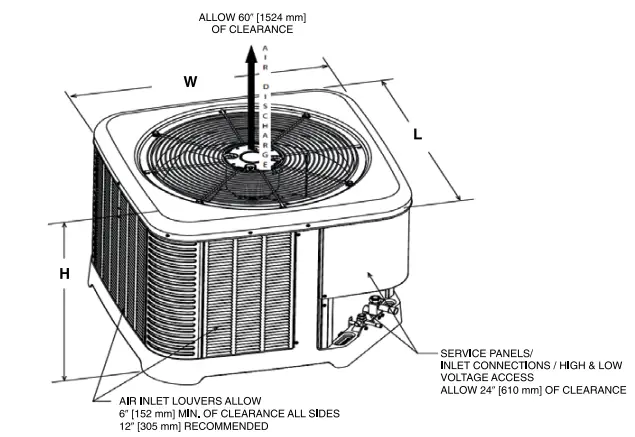
Unit Dimensions
| MODEL NO. | OPERATING | SHIPPING | ||||||||||
| H (Height) | L (Length) | W (Width) | H (Height) | L (Length) | W (Width) | |||||||
| INCHES | mm | INCHES | mm | INCHES | mm | INCHES | mm | INCHES | mm | INCHES | mm | |
| RP14AZ18**1 | 25.00 | 635 | 29.75 | 756 | 29.75 | 756 | 27.90 | 709 | 33.25 | 845 | 33.25 | 845 |
| RP14AZ18**2 | 25.00 | 635 | 29.75 | 756 | 29.75 | 756 | 27.90 | 709 | 33.25 | 845 | 33.25 | 845 |
| RP14AZ24 | 25.00 | 635 | 29.75 | 756 | 29.75 | 756 | 27.90 | 709 | 33.25 | 845 | 33.25 | 845 |
| RP14AZ30 | 27.00 | 686 | 33.75 | 857 | 33.75 | 857 | 30.08 | 764 | 37.64 | 956 | 37.64 | 956 |
| RP14AZ36 | 35.00 | 889 | 33.75 | 857 | 33.75 | 857 | 38.35 | 974 | 37.64 | 956 | 37.64 | 956 |
| RP14AZ42 | 35.00 | 889 | 33.75 | 857 | 33.75 | 857 | 38.35 | 974 | 37.64 | 956 | 37.64 | 956 |
| RP14AZ48 | 35.00 | 889 | 33.75 | 857 | 33.75 | 857 | 38.35 | 974 | 37.64 | 956 | 37.64 | 956 |
| RP14AZ60 | 45.00 | 1143 | 35.75 | 908 | 35.75 | 908 | 48.50 | 1232 | 39.37 | 1000 | 39.37 | 1000 |
Designates Metric Conversions
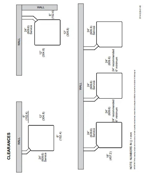
CLEARANCES
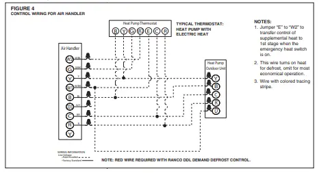
Control Wiring
Application Guidelines
- Intended for outdoor installation with free air inlet and outlet. Outdoor fan external static pressure available is less than 0.01-in. wc.
- Minimum outdoor operation air temperature for cooling mode without low-ambient operation accessory is 55°F (12.8°C).
- Maximum outdoor operating air temperature is 125°F (51.7°C).
- For reliable operation, unit should be level in all horizontal planes.
- Use only copper wire for electric connections at unit. Aluminum and clad aluminum are not acceptable for the type of connector provided.
- Do not apply capillary tube indoor coils to these units.
- Factory–supplied filter drier must be installed.
Refrigerant Line Size Information
| SINGLE AND TWO-STAGE HEAT PUMPS | |||||||||
|
UNIT SIZE | MAX. LIQUID LINE SIZE | SUCTION LINE SIZE | OUTDOOR UNIT ABOVE OR BELOW INDOOR UNIT EQUIVALENT LENGTH IN FEET | ||||||
| 0-15 | 16-25 | 26-50 | 51-80 | 81-100 | 101-125 | 126-150 | |||
| MAXIMUM VERTICAL SEPARATION/CAPACITY MULTIPLIER | |||||||||
| 1.5 TON | 3/8″ | 1/2″ | 15 / 1 | 25 / 1 | 50 / 0.99 | 80 / 0.97 | 100 / 0.97 | 115 / 0.96 | 115 / 0.95 |
| 5/8″ | 15 / 1 | 25 / 1 | 50 / 1 | 80 / 0.99 | 100 / 0.99 | 115 / 0.99 | 115 / 0.98 | ||
| 3/4″ | 15 / 1 | 25 / 1 | 50 / 1 | 80 / 0.99 | 100 / 0.99 | 115 / 0.99 | 115 / 0.98 | ||
| 2 TON | 3/8″ | 5/8″ | 15 / 1 | 25 / 1 | 50 / 0.99 | 80 / 0.98 | 100 / 0.97 | 100 / 0.96 | 95 / 0.95 |
| 3/4″ | 15 / 1 | 25 / 1 | 50 / 1 | 80 / 0.99 | 100 / 0.99 | 100 / 0.99 | 95 / 0.98 | ||
| 2.5 TON | 3/8″ | 5/8″ | 15 / 1 | 25 / 0.99 | 50 / 0.98 | 80 / 0.97 | 95 / 0.96 | 90 / 0.94 | 85 / 0.93 |
| 3/4″ | 15 / 1 | 25 / 1 | 50 / 0.99 | 80 / 0.99 | 95 / 0.98 | 90 / 0.98 | 85 / 0.97 | ||
| 3 TON | 3/8″ | 5/8″ | 15 / 1 | 25 / 0.99 | 50 / 0.97 | 80 / 0.95 | 85 / 0.94 | 80 / 0.92 | 75 / 0.9 |
| 3/4″ | 15 / 1 | 25 / 1 | 50 / 0.99 | 80 / 0.98 | 85 / 0.98 | 80 / 0.97 | 75 / 0.96 | ||
| 7/8″ | 15 / 1 | 25 / 1 | 50 / 1 | 80 / 0.99 | 85 / 0.99 | 80 / 0.99 | 75 / 0.98 | ||
| 3.5 TON | 3/8″ | 3/4″ | 15 / 1 | 25 / 0.99 | 50 / 0.98 | 80 / 0.97 | 80 / 0.97 | 70 / 0.96 | 65 / 0.95 |
| 7/8″ | 15 / 1 | 25 / 1 | 50 / 0.99 | 80 / 0.99 | 80 / 0.99 | 70 / 0.98 | 65 / 0.98 | ||
| 4 TON | 3/8″ | 3/4″ | 15 / 1 | 25 / 0.99 | 50 / 0.98 | 75 / 0.97 | 70 / 0.96 | 60 / 0.95 | 50 / 0.94 |
| 7/8″ | 15 / 1 | 25 / 1 | 50 / 0.99 | 75 / 0.99 | 70 / 0.98 | 60 / 0.98 | 50 / 0.97 | ||
| 5 TON | 3/8″ | 3/4″ | 15 / 1 | 25 / 0.99 | 50 / 0.97 | 65 / 0.95 | 45 / 0.94 | 30 / 0.92 | 15 / 0.9 |
| 7/8″ | 15 / 1 | 25 / 0.99 | 50 / 0.99 | 65 / 0.98 | 45 / 0.97 | 30 / 0.96 | 15 / 0.96 | ||
NOTES:
- Maximum Equivalent Line Length may not exceed 250′.
- Maximum Actual Line Length may not exceed 200′.
- Light Grey shaded areas are considered long line and may require accessories as recommended in Long Line Set
- Refer to supplemental Long Line Set Guide for applications that require liquid line size other than 3/8″.
- DO NOT use suction line traps in the suction riser as this adds additional unwanted pressure drop in the
Refrigerant Line Size Information (Con’t.)
| SINGLE AND TWO-STAGE HEAT PUMPS | |||||||||
|
UNIT SIZE | MAX. LIQUID LINE SIZE | SUCTION LINE SIZE | OUTDOOR UNIT ABOVE OR BELOW INDOOR UNIT EQUIVALENT LENGTH IN METERS | ||||||
| 0-5 | 5.5-8 | 8.5-15 | 15.5-24 | 24.5-30 | 30.5-38 | 38.5-46 | |||
| MAXIMUM VERTICAL SEPARATION/CAPACITY MULTIPLIER | |||||||||
| 1.5 TON | 3/8″ | 1/2″ | 5 / 1 | 8 / 1 | 15 / 0.99 | 24 / 0.97 | 30 / 0.97 | 35 / 0.96 | 35 / 0.95 |
| 5/8″ | 5 / 1 | 8 / 1 | 15 / 1 | 24 / 0.99 | 30 / 0.99 | 35 / 0.99 | 35 / 0.98 | ||
| 3/4″ | 5 / 1 | 8 / 1 | 15 / 1 | 24 / 0.99 | 30 / 0.99 | 35 / 0.99 | 35 / 0.98 | ||
| 2 TON | 3/8″ | 5/8″ | 5 / 1 | 8 / 1 | 15 / 0.99 | 24 / 0.98 | 30 / 0.97 | 30 / 0.96 | 29 / 0.95 |
| 3/4″ | 5 / 1 | 8 / 1 | 15 / 1 | 24 / 0.99 | 30 / 0.99 | 30 / 0.99 | 29 / 0.98 | ||
| 2.5 TON | 3/8″ | 5/8″ | 5 / 1 | 8 / 0.99 | 15 / 0.98 | 24 / 0.97 | 29 / 0.96 | 27 / 0.94 | 26 / 0.93 |
| 3/4″ | 5 / 1 | 8 / 1 | 15 / 0.99 | 24 / 0.99 | 29 / 0.98 | 27 / 0.98 | 26 / 0.97 | ||
| 3 TON | 3/8″ | 5/8″ | 5 / 1 | 8 / 0.99 | 15 / 0.97 | 24 / 0.95 | 26 / 0.94 | 24 / 0.92 | 23 / 0.9 |
| 3/4″ | 5 / 1 | 8 / 1 | 15 / 0.99 | 24 / 0.98 | 26 / 0.98 | 24 / 0.97 | 23 / 0.96 | ||
| 7/8″ | 5 / 1 | 8 / 1 | 15 / 1 | 24 / 0.99 | 26 / 0.99 | 24 / 0.99 | 23 / 0.98 | ||
| 3.5 TON | 3/8″ | 3/4″ | 5 / 1 | 8 / 0.99 | 15 / 0.98 | 24 / 0.97 | 24 / 0.97 | 21 / 0.96 | 20 / 0.95 |
| 7/8″ | 5 / 1 | 8 / 1 | 15 / 0.99 | 24 / 0.99 | 24 / 0.99 | 21 / 0.98 | 20 / 0.98 | ||
| 4 TON | 3/8″ | 3/4″ | 5 / 1 | 8 / 0.99 | 15 / 0.98 | 23 / 0.97 | 21 / 0.96 | 18 / 0.95 | 15 / 0.94 |
| 7/8″ | 5 / 1 | 8 / 1 | 15 / 0.99 | 23 / 0.99 | 21 / 0.98 | 18 / 0.98 | 15 / 0.97 | ||
| 5 TON | 3/8″ | 3/4″ | 5 / 1 | 8 / 0.99 | 15 / 0.97 | 20 / 0.95 | 14 / 0.94 | 9 / 0.92 | 5 / 0.9 |
| 7/8″ | 5 / 1 | 8 / 0.99 | 15 / 0.99 | 20 / 0.98 | 14 / 0.97 | 9 / 0.96 | 5 / 0.96 | ||
NOTES:
- Maximum Equivalent Line Length may not exceed 76
- Maximum Actual Line Length may not exceed 61
- Light Grey shaded areas are considered long line and may require accessories as recommended in Long Line Set
- Refer to supplemental Long Line Set Guide for applications that require liquid line size other than 3/8″.
DO NOT use suction line traps in the suction riser as this adds additional unwanted pressure drop in the system
Performance Data @ AHRI Standard Conditions – Cooling
| DESIGNATED TESTED COMBINATION (DTC) | ||||||||||||||||||
| OUTD | AIR HA | TOTAL CAPA CITY BTU/H [kW] | NET SEN SIBLE BTU /H [kW] | NET LATENT BTU/H [kW] | SEE | EE | IND | 47 D EG REE HEA TING CAPA CITY BTU /H [KW] | 47 DEG | 17 DEG REE HEA TING CAPA CITY BTU/H [KW] | 17 DEG | REG ION IV HSPF2 | ||||||
| RP14AZ18AJ1 | RH2TZ24 17STANN | 17100 | [5.0] | 13100 | [3.8] | 4000 | [1.2] | 14.3 | 9.0 | 575 | [271.4] | 17100 | [5.0] | 3.78 | 11100 | [3.3] | 2.56 | 7.5 |
| RP14AZ18AJ2 | RH2TZ24 17STANN | 17100 | [5.0] | 13100 | [3.8] | 4000 | [1.2] | 14.3 | 9.0 | 550 | [259.6] | 17100 | [5.0] | 3.58 | 11000 | [3.2] | 2.52 | 7.5 |
| RP14AZ24AJ2 | RH2TZ24 17STANN | 22800 | [6.7] | 17500 | [5.1] | 5300 | [1.6] | 14.3 | 9.0 | 775 | [365.8] | 22800 | [6.7] | 3.51 | 14600 | [4.3] | 2.55 | 7.5 |
| RP14AZ30AJ2 | RH2TZ36 17STANN | 28600 | [8.4] | 21900 | [6.4] | 6700 | [2.0] | 14.3 | 9.0 | 950 | [448.4] | 28600 | [8.4] | 3.56 | 18200 | [5.3] | 2.57 | 7.5 |
| RP14AZ36AJ2 | RH2T Z3617STANN | 34200 [10.0] | 26200 | [7.7] | 8000 | [2.3] | 14.3 | 9.0 | 1050 [495.5] | 34200 [10.0] | 3.27 | 23600 | [6.9] | 2.49 | 7.5 | |||
| RP14AZ42AJ2 | RH2TZ4 821STANN | 39500 [11.6] | 30300 | [8.9] | 9200 | [2.7] | 14.3 | 9.0 | 1275 [601.7] | 39500 [11.6] | 3.69 | 25500 | [7.5] | 2.67 | 7.5 | |||
| RP14AZ48AJ2 | RH2TZ4 821STANN | 45500 [13.3] | 34900 [10.2] | 10600 [3.1] | 14.3 | 9.0 | 1450 [684.3] | 45500 [13.0] | 3.65 | 27500 | [8.1] | 2.54 | 7.5 | |||||
| RP14AZ60AJ2 | RH2TZ6 024STANN | 55500 [16.3] | 42600 [12.5] | 12900 [3.8] | 14.3 | 9.0 | 1800 [849.5] | 55500 [16.3] | 2.66 | 34000 [10.0] | 2.56 | 7.5 | ||||||
NOTE: This data includes DTC (Designated Test Combination) ratings and is for reference purposes only. A full listing of official ratings and system match-ups, along with downloadable certificates, will be accessible from the AHRI website: www.ahridirectory.org later this year.

The new degree of comfort:


