Heat Pumps
RP14AZ
![]()
Endeavor™ Line Achiever ® Series
iM Heat Pumps
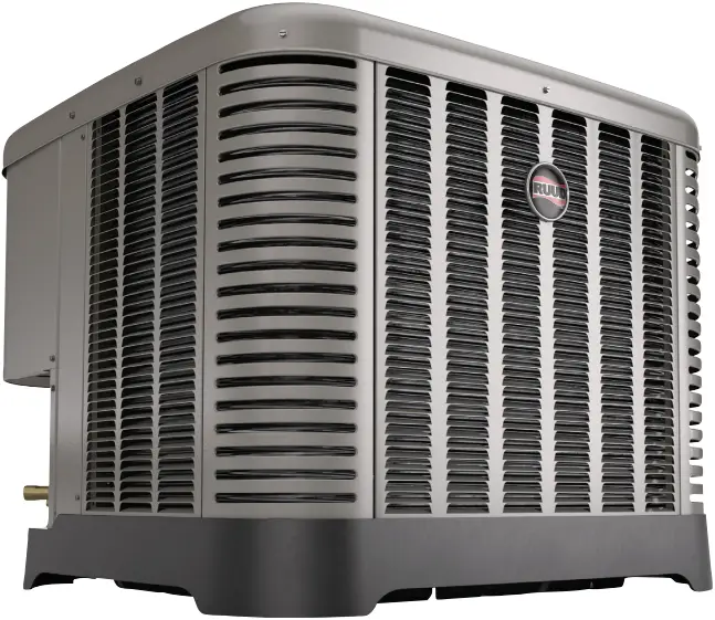
RP14AZ
Cooling Efficiencies up to: 14.3 SEER2/10.4 EER2
Heating Efficiency: 7.6 HSPF
Nominal Sizes: 1.5 to 5 Tons [5.3 to 17.6 kW]
Cooling & Heating Capacities: 17.1 kBTU to 55.5 kBTU


FORM NO. P22-828 REV. 2
Features and Benefits
- Swept Wing Fan Technology¹: Features quieter operation and improved unit acoustics
- Two-Stage Scroll Compressor²: Features two speeds (high and low) of cooling and heating, providing more precise temperature control, lower humidity and greater efficiency when compared to single stage compressors
- Inverted Reversing Valve: Allows for faster heat transfer with gravity assist shifting and reduced joint stress for increased reliability
- PlusOne® Expanded Valve Space: 3 in. – 4 in. – 5 in. service valve space—provides a minimum working area of 27-square inches for easier access
- PlusOne® Triple Service Access: 15 in. wide, industry leading corner service access, two fastener, removeable corner and individual louver panels—makes repairs easier and faster
¹Does not apply to the 3.5 and 4 Ton
²Does not apply to the 1.5 Ton 1-stage model
Heat Pumps
| R | Brand | R – Ruud |
| P | Product Category | P – Heat Pump |
| 14 | SEER2 | 14 – 14.3 SEER2 |
| A | Region | A – All Regions |
| Z | Refrigerant | Z – R-410A |
| 18 | Capacity | 18 – 18,000 [5.28 kW] 24 – 24,000 [7.03 kW] 30 – 30,000 [8.79 kW] 36 – 36,000 [10.55 kW] 42 – 42,000 [12.31 kW] 48 – 48,000 [14.07 kW] 60 – 60,000 [17.58 kW] |
| A | Major Series | A – 1st Design |
| J | Voltage | J – 208/230/1/60 |
| 1 | Type | 1 – 1-Stage 2 – 2-Stage |
| N | Controls | N – Non-Comm. |
| A | Minor Series | A – 1st Design |
[ ] Designates Metric Conversions
AVAILABLE MODELS | DESCRIPTION |
RP14AZ18AJ1NA | Endeavor™ Line Achiever ® Series 1 1/2 ton 14.3 SEER2 1-Stage iM Heat Pump-208/230/1/60 |
RP14AZ18AJ2NA | Endeavor™ Line Achiever ® Series 1 1/2 ton 14.3 SEER2 2-Stage iM Heat Pump-208/230/1/60 |
RP14AZ24AJ2NA | Endeavor™ Line Achiever ® Series 2 ton 14.3 SEER2 2-Stage Heat iM Pump-208/230/1/60 |
RP14AZ30AJ2NA | Endeavor™ Line Achiever ® Series 2 1/2 ton 14.3 SEER2 2-Stage iM Heat Pump-208/230/1/60 |
RP14AZ36AJ2NA | Endeavor™ Line Achiever ® Series 3 ton 14.3 SEER2 2-Stage iM Heat Pump-208/230/1/60 |
RP14AZ42AJ2NA | Endeavor™ Line Achiever ® Series 3 1/2 ton 14.3 SEER2 2-Stage iM Heat Pump-208/230/1/60 |
RP14AZ48AJ2NA | Endeavor™ Line Achiever ® Series 4 ton 14.3 SEER2 2-Stage iM Heat Pump-208/230/1/60 |
RP14AZ60AJ2NA | Endeavor™ Line Achiever ® Series 5 ton 14.3 SEER2 2-Stage iM Heat Pump-208/230/1/60 |
STANDARD EQUIPMENT |
| R-410A Refrigerant |
| Scroll Compressor |
| Field Installed Filter Drier |
| Front Seating Service Valves |
| Internal Pressure Relief Valve |
| Internal Thermal Overload |
| Long Line capability |
| Low Ambient capability with Kit |
| 3-4-5 Expanded Valve Space |
| Composite Basepan |
| 2 Screw Control Box Access |
| 15″ Access to Internal Components |
| Quick release louver panel design |
| No fasteners to remove along bottom |
| Optimized Venturi Airflow |
| Single row condenser coil |
| Powder coated paint |
| Rust resistant screws |
| QR code |
| External gauge ports |
| Service trays |
| External gauge ports |
| Service trays |
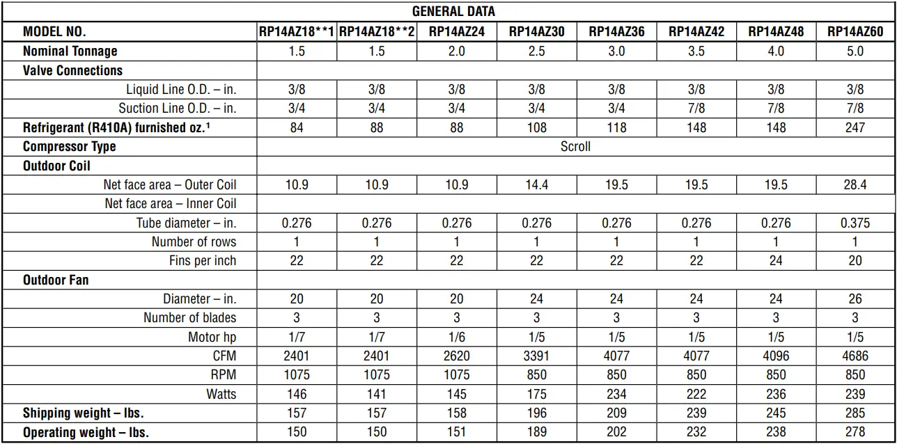
General Data
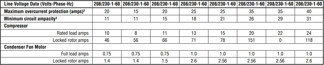
Electrical Data
¹Refrigerant charge sufficient for 15 ft. length of refrigerant lines. For longer line set requirements see the installation instructions for information about set length and additional refrigerant charge required.
²HACR type circuit breaker of fuse.
³Refer to National Electrical Code manual to determine wire, fuse and disconnect size requirements.
Accessories
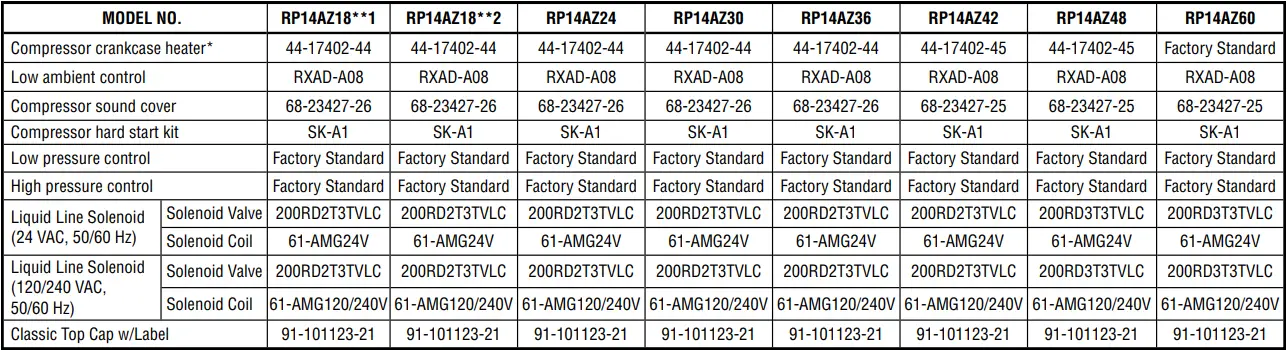
*Bi-flow kits are required when installing a liquid line solenoid on a heat pump.
Weighted Sound Power Level (dBA)
UNIT SIZE – VOLTAGE, SERIES | STANDARD RATING (DBA) | TYPICAL OCTAVE BAND SPECTRUM (dBA without tone adjustment) | ||||||
| 125 | 250 | 500 | 1000 | 2000 | 4000 | 8000 | ||
RP14AZ18A | 73 | 39.8 | 55 | 62.1 | 67.0 | 60.0 | 57.4 | 51.2 |
| RP14AZ24A | 73 | 40.4 | 55.4 | 62.5 | 65.9 | 58.7 | 56.4 | 48.9 |
RP14AZ30A | 72 | 48.9 | 55.3 | 63.6 | 61.0 | 59.1 | 56.5 | 48.7 |
| RP14AZ36A | 72 | 50.1 | 55.8 | 64.4 | 61.5 | 58.7 | 55.1 | 50.9 |
RP14AZ42A | 72 | 48.6 | 56.2 | 63.1 | 61.7 | 60.0 | 56 | 50.0 |
| RP14AZ48A | 74 | 49.3 | 56 | 64.5 | 64.5 | 60.1 | 54.9 | 47.7 |
RP14AZ60A | 74 | 43.9 | 55.2 | 63.4 | 65.8 | 61.7 | 57.9 | 52.9 |
NOTE: Tested in accordance with AHRI Standard 270-08 (not listed in AHRI)
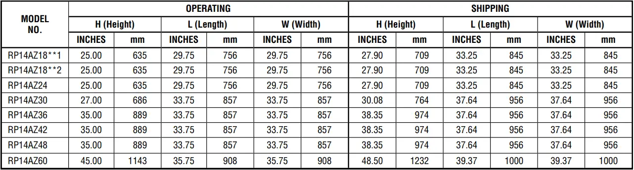
Unit Dimensions
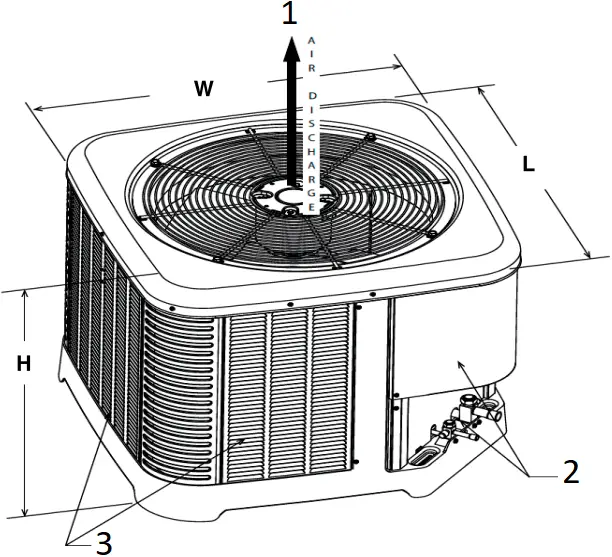
- ALLOW 60″ [1524 mm] OF CLEARANCE
- SERVICE PANELS/INLET CONNECTIONS / HIGH & LOW VOLTAGE ACCESS
ALLOW 24″ [610 mm] OF CLEARANCE - AIR INLET LOUVERS ALLOW
6″ [152 mm] MIN. OF CLEARANCE ALL SIDES
12″ [305 mm] RECOMMENDED
ST-A1226-02-00
[ ] Designates Metric Conversions
CLEARANCES
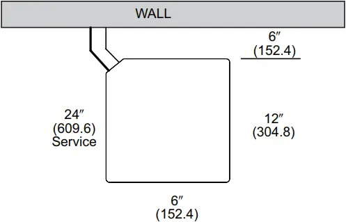
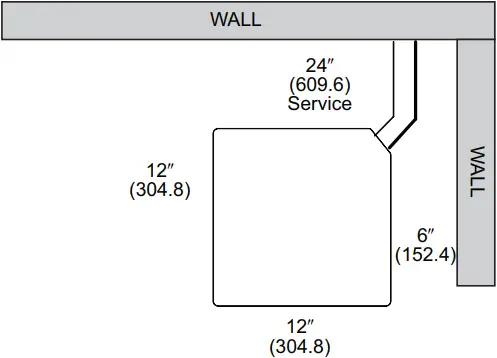
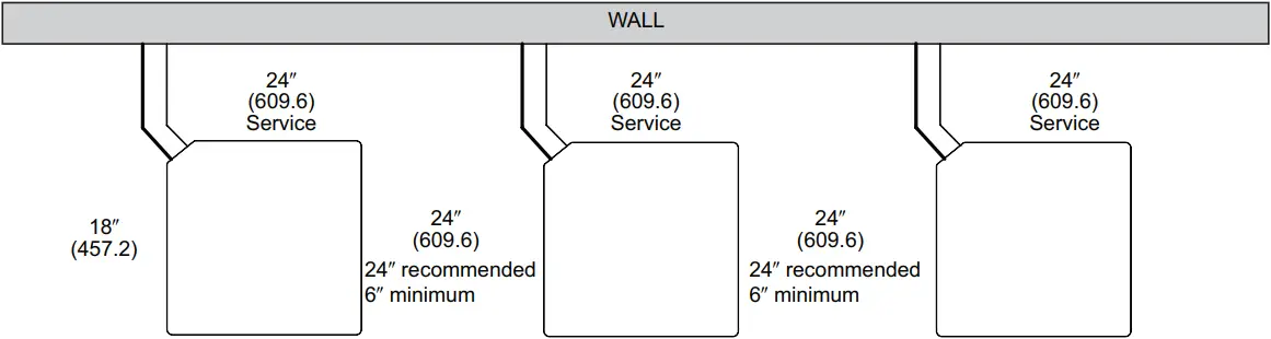
NOTE: NUMBERS IN () = mm
IMPORTANT: When installing multiple units in an alcove, roof well or partially enclosed area, ensure there is adequate ventilation to prevent re-circulation of discharge air.
ST-A1225-01-00
Control Wiring
FIGURE 4
CONTROL WIRING FOR AIR HANDLER
NOTES:
- Jumper “E” to “W2” to transfer control of supplemental heat to 1st stage when the emergency heat switch is on.
- This wire turns on heat for defrost, omit for most economical operation.
- Wire with colored tracing stripe.
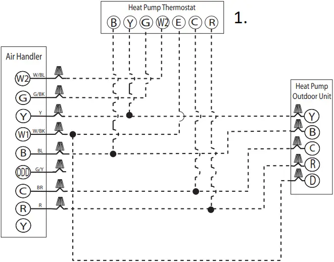
- TYPICAL THERMOSTAT:
HEAT PUMP WITH ELECTRIC HEAT
WIRING INFORMATION
Line Voltage
-Field Installed ![]()
-Factory Standard ![]()
NOTE: RED WIRE REQUIRED WITH RANCO DDL DEMAND DEFROST CONTROL.
Application Guidelines
- Intended for outdoor installation with free air inlet and outlet. Outdoor fan external static pressure available is less than 0.01-in. wc.
- Minimum outdoor operation air temperature for cooling mode without low-ambient operation accessory is 55°F (12.8°C).
- Maximum outdoor operating air temperature is 125°F (51.7°C).
- For reliable operation, unit should be level in all horizontal planes.
- Use only copper wire for electric connections at unit. Aluminum and clad aluminum are not acceptable for the type of connector provided.
- Do not apply capillary tube indoor coils to these units.
- Factory-supplied filter drier must be installed.
Refrigerant Line Size Information
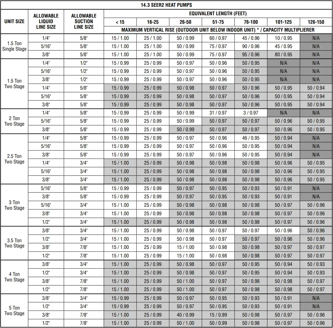
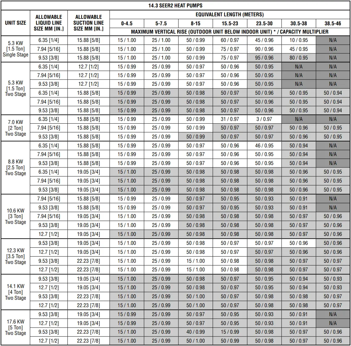
NOTES:
1) Do not exceed 200 ft linear line length.
2) *Do not exceed 100 ft vertical separation if outdoor unit is above indoor unit.
3) Always use the smallest liquid line allowable to minimize refrigerant charge.
4) Applications shaded in light gray indicate capacity multipliers between 0.90 and 0.96 which are not recommended, but are allowed.
5) Applications shaded in dark gray are not recommended due to excessive liquid or suction pressure drop.
Performance Data @ AHRI Standard Conditions – Cooling
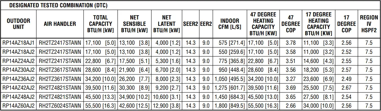
NOTE: This data includes DTC (Designated Test Combination) ratings and is for reference purposes only. A full listing of official ratings and system match-ups, along with downloadable certificates, will be accessible from the AHRI website: www.ahridirectory.org later this year.
[ ] Designates Metric Conversions
Notes
![]()
GENERAL TERMS OF LIMITED WARRANTY*
Ruud will furnish a replacement for any part of this product which fails in normal use and service within the applicable period stated, in accordance with the terms of the limited warranty.
*For complete details of the Limited and Conditional Warranties, including applicable terms and conditions, contact your local contractor or the Manufacturer for a copy of the product warranty certificate.
Conditional Parts
(Registration Required)……………………………Ten (10) Years
Before proceeding with installation, refer to installation instructions packaged with each model, as well as complying with all Federal, State, Provincial, and Local codes, regulations, and practices.
© 2023 Rheem Manufacturing Company. Ruud trademarks owned by Rheem Manufacturing Company.
In keeping with its policy of continuous progress and product improvement, Ruud reserves the right to make changes without notice.
Ruud Heating, Cooling & Water Heating • 5600 Old Greenwood Road
Fort Smith, Arkansas 72908 • www.ruud.com
Ruud Canada Ltd./Ltée • 125 Edgeware Road, Unit 1
Brampton, Ontario • L6Y 0P5 • ruud-canada.ca
PRINTED IN U.S.A. 4/23 QG FORM NO. P22-828 REV. 2


