![]() 59695230 Interline Eco Heat Pump
59695230 Interline Eco Heat Pump
Instruction Manual 
59695230 Interline Eco Heat Pump
INTERLINE ECO HEAT PUMP
Art.nr. 59695230 – 3,0 kW / Art.nr. 59695245 – 4,5 kW
Art.nr. 59695278 – 7,8 kW / Art.nr. 59695295 – 9,5 kW
PREFACE
In order to provide our customers with quality, reliability and versatility, this product has been made to strict producing standards. This manual includes all necessary information about installation, debugging, discharggin and maintenance. Please read this manual carefully before you open or maintain the unit.
The manufacturer of this product will not be held responsible if someone is injured or the unit is damaged, as a result of improper installation, debugging or unnecsesary maintenance. It is vital that the instructions within this manual are adhered at all times. Qualified personnel must install the unit.
» A qualified installer, centre, personnel or an authorized dealer, can only repair the unit.
» Maintenance and operation must be carried out according to the recommended time and frequency, as stated in this manual.
» Use genuine standard spare parts only.
» Failure to comply with these recommendations will void warranty.
» The Swimming Pool Heat Pump Unit heats the swimming pool water and keeps the temperature constant.
Our heat pump has following characteristics
Durable
The heating exchanger is made of PVC & Titanium® tube, which can withstand prolonged exposure to swimming pool water.
Easy operation
The unit is very easy to operate: switch it on and set the desired pool water temperature.
Quiet operation
The unit comprises an efficient rotary compressor and a low-noise fan motor, which guarantees its quiet operation. The unit can heat your swimming pool water when the air temperature is 10 higher.
Low cost
The operational cost is very low due to its high performance.
SPECIFICATIONS
2.1 Performance data of ECO Swimming Pool Heat Pump Unit
| Unit | Model | Eco3 | Eco•S | Eco-8 | Eco-I0 |
| Heating Capacity | kW | 3.0 | 8. | 10. | |
| BTU/h | 10200 | 15300 | 26500 | 32500 | |
| Power Input | kW | 0.7 | 1.0 | 2. | 2.0 |
| Maximum Pool Volume | 12 | 18 | 30 | 40 | |
| Running Current | A | 3.3 | 4.8 | 7.5 | 10 |
| Power Supply | V/Ph/Hz | 220-240/I/SO | 220-240/150 | 220.240/150 | 220.240/1/50 |
| Controller | Mechani al control | ||||
| Condenser | Titanium heat exchanger | ||||
| Compressor Quantity | 1 | 1 | 1 | ||
| Compressor | Rotary | Rotary | Rotary | Rotary | |
| Refrigerant | R407C/R410 | R407C/R410A | R407C/R410A | R407C/R410.1. | |
| Fan quantity | 1 | I | 1 | 1 | |
| Fan Power Input | 25 | ||||
| Fan Speed | RPM | 950 | 900 | 900 | 890 |
| Fan Direction | Horizontal | ||||
| Noise at 2m | dB (AI | 48 | 48 | 48 | 48 |
| Water Connection | mm | 50 | SO | 50 | 50 |
| Nominal Water Flow | m’/h | 2-4 | 3-5 | 5-7 | |
| Water Pressure Drop (max) | kPa | 10 | 10 | 12 | 15 |
| Unit Net Dimensions | L/W/H mm | 760/295/490 | 940/365/550 | 940/365/555 | 1015/375/615 |
| Unit Shipping Dimensions | L/W/H mm | 860/325/530 | 1045/390/590 | 1045/390/590 | 1120/395/655 |
| Net Weight /Shipping Weight | Kg | 29/32 | 36/39 | 54/57 | 63/67 |
* Measurement conditions: Dry bulb: 24 °C, Wet bulb: 19 °C , water inlet temperature: 27 °C
2.2 dimensions of swimming pool heat pump 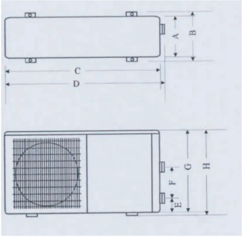
| A | B | C | D | E | F | G | H | |
| ECO-3 | 213 | 293 | 770 | 810 | 80 | 200 | 455 | 485 |
| ECO-5 | 280 | 360 | 936 | 970 | 80 | 200 | 521 | 551 |
| ECO-8 | 280 | 360 | 936 | 970 | 80 | 200 | 521 | 551 |
| ECO-10 | 301 | 370 | 1010 | 1050 | 83 | 270 | 585 | 615 |
INSTALLATION OF THE HEAT PUMP UNIT
3.1 Installation items:
The factory only provides the heat pump unit; the other items including an eventual bypass, in the illustration are necessary parts for the water system, provided by users or the installer.
Attention:
Please follow these steps when installing the heat pump:
» All feeding of chemicals to the pool water has to be done downstream of the heat pump.
» Install a bypass when the flow of the pool pump is more then 20% above the rated flow of the heat exchanger of the heat pump.
» Install the heat pump on a sodlifoundation and use the damping rubbers to eliminate vibrations and noise.
» Always keep the unit straight up. If the unit has been tilted or put on his side, allow 24h before starting the unit.
3.2 Heat pump location
The unit may be installed virtualyl anywhere outdoors. For indoor pools please consult your supplier.
Do not put the unit in an enclosed area with a limited air volume where the unit discharge air will be r-ceirculated.
Do not put the unit next to shrubs, which can block the air inlet. Schu locations deny a continuous source of fresh air, which reduces its efficiency and may prevent adequate heat delivery.
The picture below give the minimum required distances from each side of the heat pump.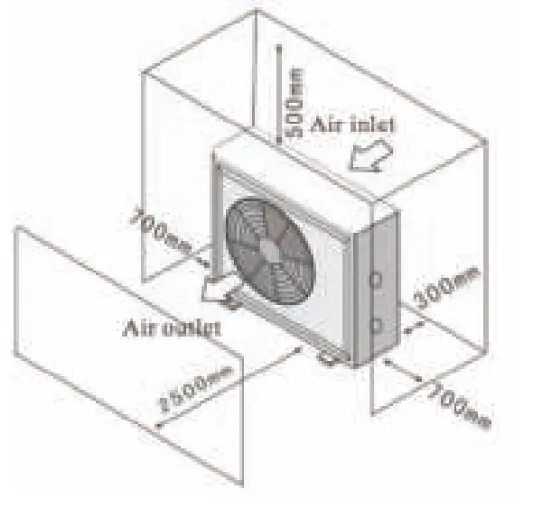 Install the heat pump where you have the best access to warm air during the swimming season.
3.3 How close to the pool?
Install the heat pump as close to the swimming pool as possible to minimize the loss of heat through the piping.
Put it on a solid base and place the rubber blocks under the heat pump to eliminate vibrations.
3.4 Check valve installation
Caution Placement of the chlonriator, water balance equipment, and the placement of injectors of chemicals, are very important aspects of the installation. All addition of chemicals have to be done downstream from the heat pump. Failure to protect the heat pump unit from chemical daemiasgnot covered under the warranty.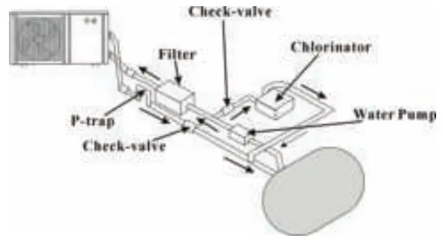 3.5 Typical configuration
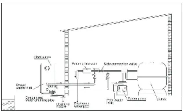 Note: the above piping connection is only an example for demonstration
3.6 Setting the bypass
With the bypass set correctly, your heat pump will deliver its best performance. The bypass has to be built as show below: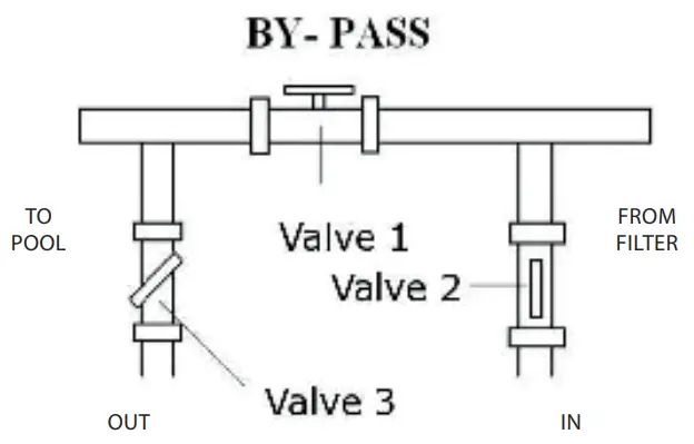 VALVE 1
Slightly closed (water pressure increased with just 100 to 200 gr)
VALVE 2
Completely open
VALVE 3
Half way open
Setting the valves of the by-pass:
» Set all 3 valves entirely open
» Slightly close valve 1 (see also 3.8 )
» Close valve 3 about half way to adjust the refrigerant pressure.
3.7 Electrical wiring
Note: Verify the local power supply and the operating voltage of the heat pump. It is recommended to use a separate circuit breaker (slow type D curve) for the heat pump together with the proper wiring characteristics (see table below). The current to the heat pump should only be applied when the filter pump is running . For example a relay controlled by the filter pump could be used to activate the current to the heat pump. Further connect the electrical supply to the junction box inside the unit. All ECO heat pumps require single-phase connection.
Grounding the heat pump is required to protect you against electrical shock caused by an eventual short circuit inside the unit.
| Model | Aansluiting (volt) | Zekering (A) | Nominale stroom (A) | Kabel (mm²) voor 15m lengte |
| ECO-3 | 220-240 | 16 | 3,3 | 1,5 |
| ECO-5 | 220-240 | 16 | 4,8 | 1,5 |
| ECO-8 | 220-240 | 20 | 7, 5 | 2,5 |
| ECO-10 | 220-240 | 20 | 10 | 2,5 |
Values in this table are only guidelines. Please check your local regulations. The heat pump is not equpiped with a flow switch or any other kind of water flow detection. Therefore, the heat pump has to be wired electrically together with the filter pump to ensure water flow while the heat pump is running.
3.8 Initial startup of the unit
Start up Procedure-after the installation is completed, you should follow these steps:
» Set the by-pass valve 1 entirely open. Turn on your filter pump. Check for water leaks and verify flow to and from the pool.
» Turn on the electrical power supply to the unit atunrdn the unit ON with the switch.Slightly close valve 1 until the heat pump starts.
» After running a few minutes, check if the air leaving the side of the unit is cooler.
» Allow the unit and pool pump to run 24 hours per day until desired pool watetremperature is reached. When the set temperature is reached, the unit just shuts off. The unit
will now automatically restart (as long as your pool pump is running) when the pool temperature drops more than 1 degree Celsius below set temperature.
Time Delay – the unit is equipped with a-m3inute built-in delay to protect control circuit components and to eliminate restart cycling and contactor chatter. This time delay will automatically restart the unit approximately 3 minutes after each circuit interruption. Even a brief power interruption will activate this delay and prevent the unit from starting unti-lmtihneut3e countdown is completed.
Several days are needed to bring the temperature of you swimming pool water to its required value.
3.8.1 Running the machine
» Running the machine
As shown below picture: when the switch is in the “OFF” position initially, screw it to “ON” position, machine will start.
» Stop the machine
As shown below picture: when the switch is in the “ON” position initially, screwing it to “OFF” position, machine will stop.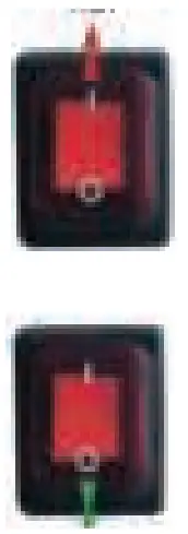 » Set the water temperature
As shown below picture, you can set inlet water temperature range from 0°C to 40°C by screwing temperature adjustment knob. Screw clockwise, setting temperature decreases. Screw anticlockwise, setting temperature increases. 3.9 Condensation
Since the Heat pump cools down the air about -812 humidity is very high, this could be as much as several liters an hour. Sometimes this condensation water is wrongly considsered a swimming pool water.
GUIDELINES
4.1 Water chemistry
Special care should be taken to keep the chemical balance of your swimming pool within limits:
| Min. | Max. | |
| pH | 7, 0 | 7, 8 |
| Free chlorine (mg/1) | 0,5 | 1,2 |
| TAC mg/1) | 80 | 150 |
| TAC | 10 | 30 |
| Salt (g/1) | 8 | |
Important: failure to keep the swimming pool water between above limits will void the warranty.
Note: when the concentration of one or more products mentioned above becomes too high, irrevocable damage to your heat pump may occur. Make sure that you always insstall water treatment equipment after the heat pump. When an automatic chemical feeder is installed in the plumbing, it must be installed downstream of the heat pump. A check valve must be installed between the heat pump and the chemical feeder to prenvteback-siphoning of chemically saturated water into the heat pump where it will damage the components.
4.2 Wintering
Caution: failure to winterize could cause damage to the heat pump and will void warranty. In areas where freezing temperatures occur, you should protect your pump, filter and heat pump from the elements.
Perform the following steps to completely drain the heat pump:
» Turn off the electrical power to the heat pump at the main breaker panel.
» Shut off the water supply to the heat pump: close valves 2 and 3 on the bypass completely.
» Disconnect the water inlet and outlet and let the water drain from the heat pump.
» Re-connect the water inlet and outlet loosely to prevent debris entering the connections.
4.3 Spring startup
If your heat pump has been winterized, perform the following steps when starting the system in the spring:
» Inspect the system for any debris or structural problems.
» Connect the water inlet and outlet unions firmly.
» Turn on the filter pump to supply water to the heat pump. Adjust the bypass to allow water flow through the heat pump.
» Turn on the electrical power to the heat pump at the main breaker panel.
4.4 Owner inspection
The ECO heat pumps are designed and constructed to provide long performance life when installed and roapted properly under normal conditions. Periodic inspections are important to keep your heat pump running safely and efficiently through the years.
The following basic guidelines are suggested for your inspection:
» Make sure the front of the unit is accesibsle for future service.
» Keep the surrounding areas of the heat pump clear of all debris.
» Keep all plants and shrubs trimmed and away from the heat pump.
» Keep lawn sprinkler heads from spraying on the heat pump to prevent corrosion and damage. Use a decftloer if needed.
» If the unit is installed under a very sharp roof pitch or under a roof without a gutter, a gutter or diverter should be fitted to prevent excessive water from pouring down into the unit.
» Do not use the heat pump if any part has been underwater. Immediately call a qualified professional technician to inspect the heat pump and replace any part of the control system, which has been submerged.
The heat pump will produce condensation (water) while in operation. The heat pump base is desoiganlelodwt the condensation to exit through the bottom drain port. The condensation will increase as the outdoor air humidity level increases. Check the following at regular intervals to ensure proper condensate drainage:
» Visually inspect and clear the bottom drain port of any debris that could clog the port.
» Keep the air intake area and discharge area clear of debris so the airflow through the heat pump is not restricted. The cooler discharge air should not accumulate and be drawn into the side air intackoeils.
During normal operation, the heat pump produces ten to twenty liters of condensate per hour. If condensate drainage is above this range during operation or if water continues to drain from the base when the heat pump is not in operation for more than hour, a leak in the internal plumbing may have occurred. Call a qualified heat pump technician to investigate the problem.
Note: A quick way to verify that the water running trough the drain is condensation water is to shut off the unit and keep the pool pump running. If the water stops running out of the base pan, it is condensation water. An even quicker way – test the drain water for chlorin – if there is no chlorine present, then it’s condensation.
MAINTENANCE AND INSPECTION
5.1 Maintenance
Check the water supply to the unit often. Low water flow and air entering into the system should be avoided, as this will diminish the units a result of the dirty or clogged filter. The area around the unit should be dry, clean and well ventilated. Clean the side heating exchanger regularly to maintain good heat exchange and to save energy.
Only a certified technician should service the operation pressure of the refrigerant system.
Check the power supply and cable connection often. Should the unit begin to operate abnormally, switch it off and contact a qualified technician.
In winter, please discharge all water from the water pump and other systems prevent damage from freezing.
You should discharge the water at the bottom of the heat pump if the unit will not work for an extended period of time.
You should check the unit throughly and fill the system with water fully before using it after a prolonged period of no usage.
5.2 Trouble shooting guide
Improper installation will create an electrical hazard, which could result in death or serious injury to pool users, installers, or others due to electrical shock, and may also causes damage to property. Do not attempt any internal adjustments inside the heater.
» Keep your hands and hair clear of the fan blades to avoid injury.
» If you are not familiar with your pool filtering system and heater:
A. Do not attempt to adjust or service without consulting your dealer, professional pool or air conditioning contractor.
B. Read the entire installation and users guide before attempting to use, service or adjust the heater or pool filtering system.
Note: Turn off power to the unit prior to attempt service or repair.
| Issue | Cause | Solution |
| Heat pump not working | 1. No electricity 2. Heat pump switched off 3. Wrong temperature 4. Bypass not set 5. No gas pressure 6. Time delay still active 7. Air temperature below 8 degrees | 1. Turn on the power 2. Turn on the heat pump 3. Set the correct temperature 4. Set the bypass 5. Contact your installer 6. Wait for the heat pump to start 7. Wait for it to warm up |
| Insufficient heating | 1. Air blockage 2. Icing on the evaporator 3. Bypass not set 4. Water flow rate too high | 1. Remove the obstacles 2. Turn off the heat pump temporarily 3. Set the bypass 4. Set the bypass |
5.3 Checklist at installation 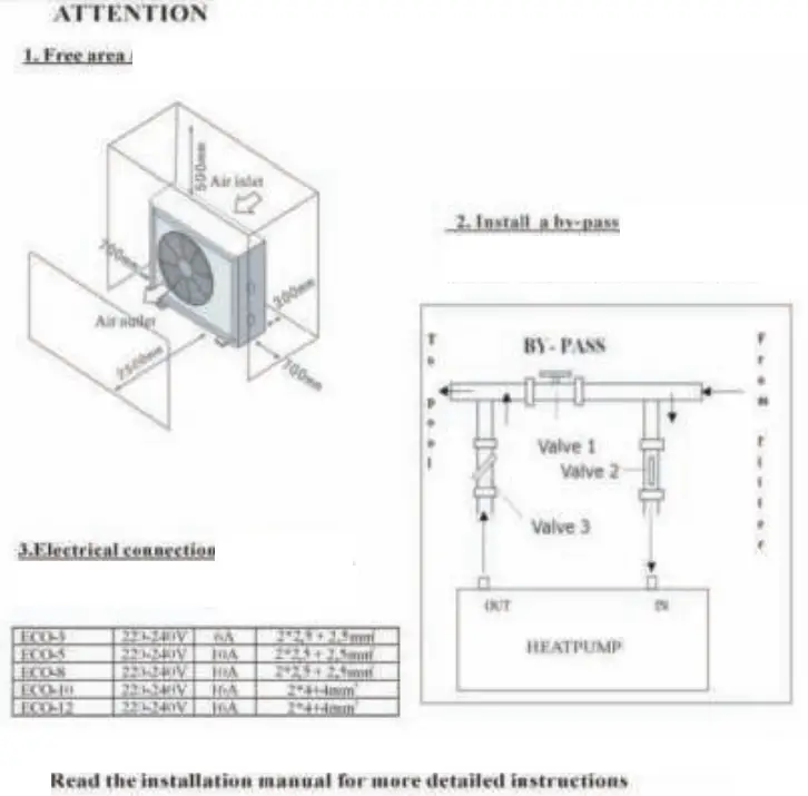
DETAILED SPECIFICATIONS
6.1 Electrical wiring diagram of the heat pump 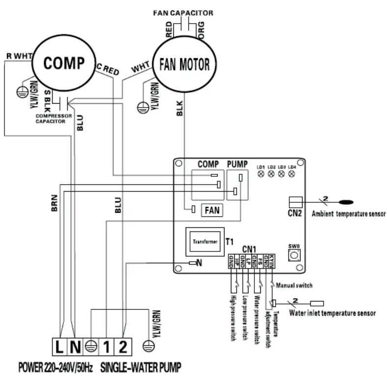
TROUBLESHOOTING
| Malfunction LED1 | LED2 | LED3 | LED4 | Solution | |
| Standby | |||||
| Ambient sensor failure | Check the cable connection of the ambient temp. sensor/ replace a new sensor | ||||
| High pressure protection | Refrigerant system pressure is high, check pressure gauge, increase the water volume | ||||
| Low pressure protection | x | x | Refrigerant system pressure is low, check pressure gauge, refeed refrigerant | ||
| Waterpressure switch failure | x | Check the water inlet/ outlet connection is correct or not, increase the water volume | |||
| Low ambient temperature protection | x | Air temp lower than 8°C, stop the heat pump until temp over 8°C. | |||
FIGURES OF THE PUMP
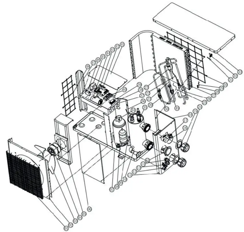
8.1 PARTS LIST
| NO | Part Name | NO | Part Name |
| 1 | Front grill | 26 | Collection pipes |
| 2 | Front panel | 27 | Evaporator |
| 3 | Fan blade | 28 | Pipes temperature sensor collet |
| 4 | Fan motor | 29 | Pipes temperature sensor |
| 5 | Fan motor bracket | 30 | Back grill |
| 6 | maintain board | 31 | Ambient temperature sensor |
| 7 | Base tray | 32 | Ambient temperature sensor clip |
| 8 | Compressor | 33 | Top cover |
| 9 | Temperature sensor of water-in | 34 | Compressor wiring clip |
| 10 | Titanium heat exchanger | 35 | Water flow switch |
| 11 | Panel on the side | 36 | Isolation panel |
| 12 | Drainage hole plug | 37 | Electric box |
| 13 | Suction valve | 38 | Cable fixing clamp-up |
| 14 | Cable joints | 39 | Cable fixing clamp-down |
| 15 | Pressure guage | 40 | Terminal blocks |
| 16 | Thermostat | 41 | Controller box cover |
| 17 | Mechanical switch | 42 | PC board |
| 18 | Panel on the side | 43 | Capacitance clamp |
| 19 | Water inlet/outlet bolt | 44 | Capacitance |
| 20 | Suction pipe | 45 | Transformer |
| 21 | Exhaust pipe | 46 | Fan motor capacitance |
| 22 | Pipe (4 way valve to evaporator) | 47 | Pillar |
| 23 | Pipe (4 way valve to heat exchanger) | 48 | Grill on the side |
| 24 | Water inlet/outlet screw cap | 49 | low pressure protection switch |
| 25 | Cappillary | 50 | high pressure protection switch |
WARRANTY
LIMITED WARRANTY
Thank you for purchasing our heat pump.
We warrant all pans to be free from manufacturing defects in materials and workmanship for a period of two years from the date of retail purchase.
This warranty is limited to the lust retail purchaser, is not transferable, and dots not apply to products that have been moved from their original installation sites. The liability of the m.3nufacnir shall not exceed the repair or replacement of defective pans and does not include any costs for labor to remove and reinstall the defective pan, transportation to or from the factory, and any other materials required to make the repair. This warranty does not cover failures or malfunctions resulting from the following:
- Failure to properly install, operate or maintain the product in accordance with our published “Installation & Instruction Manual” provided with the product.
- The workmanship of any installer of the product.
- Not maintaining a proper chemical balance in your pool Ipll level between 7,0 and 7,
- Total Alkalinity (TA) between 80 to 120 ppm. Free Chlorine between 0,5 — 1,2m2/1. Total Dissolved Solids (TDS) less than 1200 ppm. Salt maximum 3g/11 4. Abuse, alteration, accident, fire, flood, lightning, rodents, insects, negligence or acts of Gods.
- Scaling, (meting or other conditions causing inadequate water circulation.
- Operating the product at water flow rates outside the published minimum and maximum specifications. 7. Use of non-factory authorized parts or accessories in conjunction with the product.
- Chemical contamination of combustion air or improper use of sanitizing chemicals, such as introducing sanitizing chemicals upstream of the heater and cleaner hose or through the skimmer.
- Overheating, incorrect wire runs, improper electrical supply, collateral damage caused by failure of 0-rings, DE grids or cartridge elements, or damage caused by running the pump with insufficient quantities of water.
LIMITATION OF LIABILITY
This is the only warranty given by Manufacturer. No one is authorized to make any other warranties on our behalf. THIS WARRANTY IS IN LIEU OF ALL OTHER WARRANTIES, EXPRESSED OR IMPLIED, INCLUDING BUT NOT LIMITED TO ANY IMPLIED WARRANTY OF FITNESS FOR A PARTICULAR PURPOSE AND MERCHANTABILITY. WE EXPRESSLY DISCLAIM AND EXCLUDE ANY LIABILITY FOR CONSEQUENTIAL, INCIDENTAL, INDIRECT OR PUNITIVE DAMAGES FOR BREACH OF ANY EXPRESSED OR LMPLIED WARRANTY.
This warranty gives you specific legal rights, which may vary, by country.
WARRANTY CLAIMS
For prompt warranty consideration. contact your dealer and provide the following information: proof of purchase, model number, serial number and date of installation. The installer will contact the factory for instructions regarding the claim and to determine the location of the nearest service center.
All returned parts must have a Returned Material Authorization number to be evaluated under the terms of this warranty Fnr further infnrmatinn. please contact sour local agent.![]()


