TESY 206963 Hot Water Heat Pump User Manual
Introduction
Dear Customer,
Thank you for having purchasing this product.
We, has always paid a great deal of attention to environmental problems, therefore, it has used technologies and materials with a low environmental impact to manufacture its products in conformity with WEEE – RоHS (2011/65/ЕU and 2012/19/EU community standards.
IMPORTANT RULES AND SAFETY INSTRUCTIONS
![]() IMPORTANT! Non observance of below described rules leads to warranty fault and the producer bear no more responsibilities for your appliance!
IMPORTANT! Non observance of below described rules leads to warranty fault and the producer bear no more responsibilities for your appliance!
- This appliance is not intended for use by persons (including children) with reduced physical, sensory or mental capabilities, or lack of experience and knowledge, unless they have been given supervision or instruction concerning use of the appliance by a person responsible for their safety.
- Children should be supervised to ensure that they do not play with the appliance.
- Children must not play with the equipment. Cleaning and maintenance intended to be carried out by the user must not be performed by unsupervised children.
- The use of the appliance for any purpose other than that it is intended is prohibited
- Do not use the storage tank if it is not filled with water.
- Installation, commissioning and maintenance of the device must be performed by qualified and authorized personnel. Do not attempt to install the device yourself.
- The appliance must only be installed in premises with normal fire resistance.
- Usage of this device at temperature and pressure level above prescribed leads to warranty violation!
- This device is intended for heating of potable water in liquid state. using different fluids in different states leads to warranty violation!
BEFORE STARTING THE UNIT!
 Read carefully the “Installation and maintenance manual”, that is an integral part of your appliance!
- Check if the unit is installed and connected according to the “Installation and maintenance manual”, that is an integral part of your appliance!
- Check if the tank is full with water!
- Check if the electric main supply is present an it is with accordance to the local regulations!
- Check that the air ducts or air inlet/outlet are not blocked!
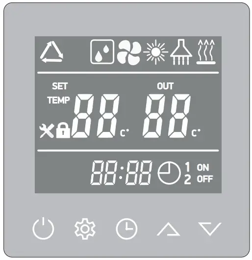
OPERATING MODES. USER INTERFACE
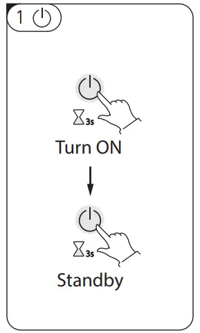
 Press this button
  and hold it for 3 seconds when the unit is in standby, the unit will be turned ‘ON’.
- Press this button and hold it for 3 seconds when the unit is running, the unit will be turned OFF – “Standby”.
- Short press this button to enter or exit the parameter setting or checking.

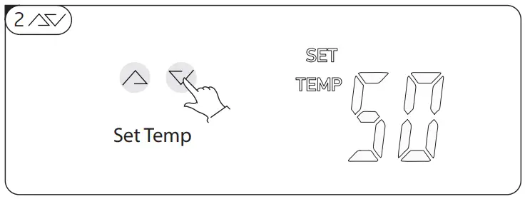
 These are the multi-purpose buttons. They are used for the temp setting, parameter setting, parameter checking, clock adjustment and adjustment of the timer.
- During running status, press
 or button to adjust the setting temperature directly.
 - Press these buttons when the unit is on clock setting status, the hour(s) and the minute(s) of the clock time can be adjusted.
- Press these buttons when the unit is on timer setting status, the hour(s) and the minute(s) of the timer ‘ON’/’OFF’ can be adjusted.

![]() Unlock the screen:
Unlock the screen:
- Press the button for at least 3 sec. The buttons are unlocked and the symbol
 will appear. After 1 minute the buttons will lock automatically
Clock setting:
- After power on, short press
 button to enter the clock setting interface, hour and minute icons “88:88” flash simultaneously.
 - Short press button to switch hour/minute setting, press the and buttons to set the exact hour(s) and minute(s);
- Press button again to confirm the settings/changes and exit.
Timer setting:
- After power on, long press button for 5 seconds to enter the timer setting interface, the timer on icon
 and hour icon “88:” flash simultaneously;
 - Press the and buttons to set the exact hour(s).
- Press button to transfer to minute setting, minute icon “:88” flash, press the and buttons to set the exact minute(s).
- Press the button
 to confirm. In this moment, timer on icon stops flashing that means “timer on” is set.
IMPORTANT: If step No4 is omitted, timer on icon will stay flashing and “timer on” is not set! - Press button again to transfer to timer off setting, the “timer off” icon and hour icon “88:” flash simultaneously.
- Press the and buttons to change the hour(s).
- Press button button to transfer to minute setting, minute icon “:88” flash, press the and buttons to change the minute(s).
- Press button to confirm. In this moment, “timer off” icon stops flashing that means “timer off” is set.
IMPORTANT: If step No8 is omitted, timer off icon will stay flashing and “timer off” is not set! - Press button again to save and exit the timer setting interface.
IMPORTANT:
- If step No4 is omitted and all steps from 5 to 9 are done, “timer off” will be set and in stand by mode icon will light on display.
- If step No8 is omitted, and all steps from 1 to 4 are done, “timer on” will be set and in stand by mode icon will light on display.
- If all steps from 1 to 9 are done, both “timer on” and “timer off” will be set and icon will light on display.
Timer cancelling:
Do all steps from 1 to 9, without steps No4 and No8. The timer will be cancelled.
NOTE: 1) The timer settings are automatically repeating.
NOTE: 2) The timer settings are still valid after a sudden power cut.
![]() 1) Short press the button
1) Short press the button![]() and the working mode could be set.
and the working mode could be set.
- AUTO mode. (Heat pump + E-heater will work according to the controller logic). The symbol
 will appear on the display.
 - GREEN mode. (Only heat pump will work at normal working condition). The symbol
 will appear on the display.
 - BOOST mode (Heat pump + E-heater will work at the same time). The symbol +
 will appear on the display.
 - E-HEATER mode. (Only E-heater will work). The symbol will appear on the display.
- VENTILATION mode. (Only fan will work). The symbol
 will appear on the display.
2) Check the system parameters
- In any status, press this button and hold for 3 seconds, entry the system parameter checking interface.
- Press the and buttons to check the system parameters.
MEANING OF LED ICONS!
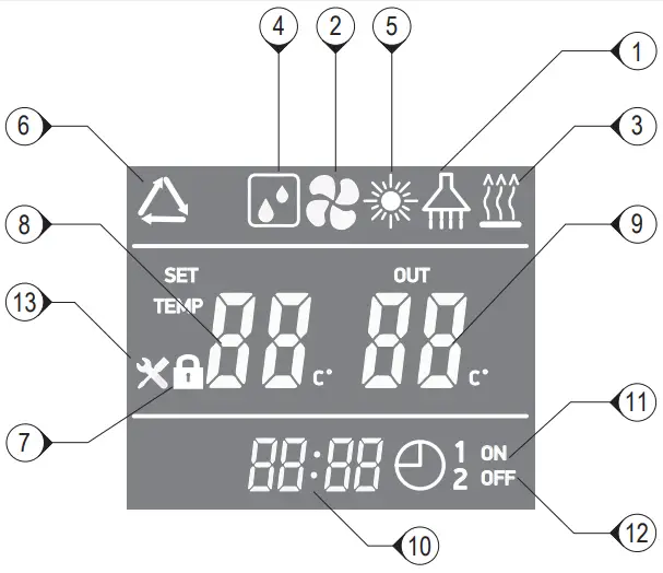
| 1 | Hot water available | The icon indicates that the domestic hot water temperature has reached the set point. The hot water is available for use. Heat pump is in standby. |
| 2 | Fan ventilation | The icon indicates that the fan ventilation function is enabled. |
| 3 | Electrical heating | The icon indicates that the electrical heating function is enabled. The electrical heater will work ac- cording to the control program. |
| 4 | Defrosting | The icon indicates that the defrosting function is enabled. This is an automatic function; the system will enter or exit the defrosting according to the internal control program |
| 5 | “Green” mode | The icon indicates that the unit is operating in “Green” mode. |
| 6 | “AUTO” mode | The icon indicates that the unit is operating in “AUTO” mode. |
| 5+3 | “BOOST” mode | The icons indicate that the unit is operating in ‘BOOST– mode. |
| 7 | Key lock | The icon indicates the key lock function is enabled. The keys Will be deactivated until this function is disabled |
| 8 | Left temperature display | The display shows the set water temperature. In case any malfunction occurs, this section will display the related error code P. |
| 9 | Right temperature display’ | The icon indicates reached water temperature. When checking or adjusting the parameters, this section will display the related parameter value |
| 10 | Time display | The display shows the clock time or timer time. |
| 11 | Timer ‘ON’ | The icon indicates that the timer ‘ON’ function is enabled. |
| 12 | Timer ‘OFF’ | The icon indicates that the timer ‘OFF’ function is enabled. |
| 13 | Error | The icon indicates there is a malfunction. |
OPERATING MODES
| MODE | AMBIENT TEMP | Lower tank water temp or Upper tank water temp *(when lower tank water temp sensor has problem) | |||||
| ≤-5 °C | ≥-2 °C | >43 °C | ≤41 °C | >60 °C | ≤58 °C | ||
AUTO mode | Compressor | OFF | ON | OFF | ON | OFF | ON |
| E-heater | ON | OFF | ON | OFF | |||
GREEN mode | Compressor | OFF | ON | OFF | ON | OFF | ON |
| E-heater | ON | OFF | ON | OFF | |||
BOOST mode | Compressor | OFF | ON | OFF | ON | OFF | ON |
| E-heateR | Acc. to logic | Acc. to logic | Acc. to logic | Acc. to logic | Acc. to logic | Acc. to logic | |
E-Heater mode | Acc. to logic | Acc. to logic | Acc. to logic | Acc. to logic | Acc. to logic | Acc. to logic | |
Fan mode | Only the fan will working at low speed, compressor and E-heater are OFF | ||||||
AUTO mode
When the unit is ON, the main controller “understands” how to reach the desired temperature in a few hours, through the rational use of the heat pump and, if necessary, the E-heater will work too.
- Temperature range 38°C~60°C default 50°C
GREEN mode
- Temp range 38°C~60°C default 50°C
- The compressor will work only, according to upper and lower tank water temperature.
BOOST mode
- Temp range 38°C~70°C default 50°C
- Both compressor and E-heater will work simultaneously for fastest production of hot water
E-Heater mode
- Temp range 38°C~70°C default 50°C
- Only E-heater is working!
Defrost mode
“Normal defrost”. When the coil temperature ≤ 1 °C, and the compressor accumulatively run over 45 minutes, and if after that 45 min. coil temperature is ≤ -3°C, than the defrosting operation starts.
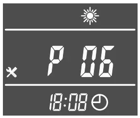
Antifreeze mode
Even when the appliance is in standby mode, if lower tank temp. ≤ 5°C, anti-frozen protection starts. The Heat pump is forced to work.
When lower tank temp. ≥ 10°C, it exits Anti-frozen protection.
Symbol P06 is flashing on display, without icon “Error”.
If both P06 and “Error” appear on display, see chapter “error codes”
Disinfection weekly cycle
The E-heater will start each week at the setting time automatically. (When the unit is off at constant temperature or at standby mode, Anti-legionnaire function is on)
When upper water tank temp. ≥ 70°C, the heater stops. When upper water tank temp. ≤ 70°C-2°C, the heater starts.
It keeps the upper water tank temp in range (70°C-2°C) to 70°C for he set disinfection time 30mins, after 30mins, then quit
the disinfection. The timer will be cleared and start to next timer cycle.
E-heater Priority level: 1) defrost or anti-frozen; 2) disinfection; 3) other controls
IF SOMETHING GOES WRONG!
- Switch off the unit! Disconnect it the from main power supply!
- Call to the service and inform them about the error code or describe all abnormalities and strange behavior or noise of your appliance!
Error codes
| Error | Code |
| Stand by | |
| Normal running | |
| Lower tank water temp. sensor failure | P01 |
| Upper tank water temp. sensor failure | P02 |
| Coil temp. sensor failure | P03 |
| Suction air temp sensor failure | PO4 |
| Ambient temp. sensor failure | P05 |
| Winter Anti-frozen protection failure | P06 |
| High pressure protection (HP Switch) | E01 |
 This symbol on the product(s) and / or accompanying documents means that used electrical and electronic equipment (WEEE) should not be mixed with general household waste. For proper treatment, recovery and recycling, please take this product(s) to designated collection points where it will be accepted free of charge. Disposing of this product correctly will help save valuable resources and prevent any potential negative effects on human health and the environment, which could otherwise arise from inappropriate waste handling.