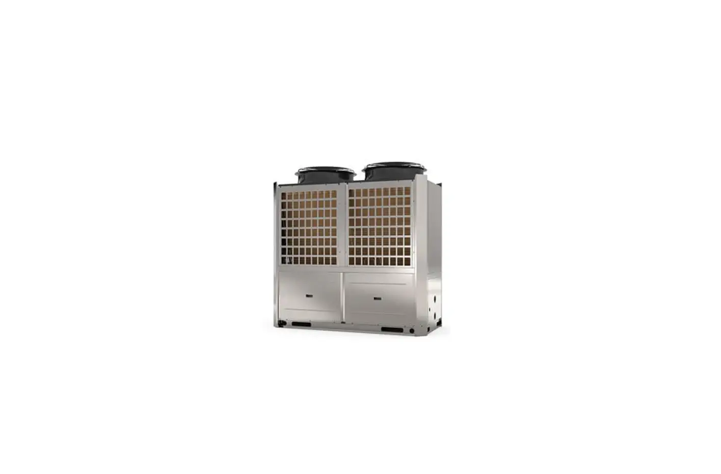
EVO HEAT Evo Max Series Commercial Hot Water Heat Pump
Introduction
This manual contains information relating to the installation, troubleshooting, operation, and maintenance of this EvoHeat unit. Instructions in this manual must always be followed. Failure to comply with these recommendations will invalidate the warranty. Should you have any questions or require technical support, call the EvoHeat office on 1300 859 933 to speak to our team.
The data and information contained in this manual is correct at the time of publishing and is subject to change without notice. For the most up to date manual, contact EvoHeat directly.
The Evo Max is ideal for commercial water heating applications that need high temperature hot water of up to 80°C. It is ideal for hospitals, nursing homes, hotels and motels, food preparation and sanitation, sterilization, industrial and laundry applications. With a higher C.O.P than traditional boilers, cutting edge technology, green refrigerants, high efficiency heat exchanger and a circulating heating method, the Evo Max can help end users save significantly on their annual hot water operating costs.
| TECHNICAL DATA | Evo Max 19 | Evo Max 35 | Evo Max 70 | Evo Max 135 | |||
| Hot Water | Heating Capacity | kW | 19 | 35 | 70 | 135 | |
| Power Input | kW | 5.3 | 9.2 | 19 | 38.6 | ||
| Conditions: | |||||||
| Air 20°C, | |||||||
| Water 65°C | |||||||
| C.O.P | 3.58 | 3.68 | 3.68 | 3.5 | |||
| Hot Water | Heating Capacity | kW | 16 | 29.5 | 58.9 | 113.7 | |
| Power Input | kW | 6 | 10.8 | 21.5 | 43.7 | ||
| Conditions: | |||||||
| Air 20°C, | |||||||
| Water 80°C | C.O.P | 2.67 | 2.74 | 2.74 | 2.6 | ||
| Max. Running Current | A | 14.3 | 32.2 | 64.6 | 108.5 | ||
| Max. Power Input | kW | 7.5 | 18.1 | 36.2 | 64.4 | ||
| Voltage/Phase | 380-415V/3/50 | 380-415/3/50 | 380-415/3/50 | 380-415/3/50 | |||
| Noise | dB(A) | 58 | 65 | 68 | 70 | ||
| Air Discharge Type | Horizontal | Horizontal | Vertical | Vertical | |||
| Fan No. | 2 | 1 | 2 | 2 | |||
| Compressor No. | 1 | 1 | 2 | 4 | |||
| Refrigerant Type | R134A | R134A | R134A | R134A | |||
| Operation Range | °C | -7 to 45 | -7 to 45 | -7 to 45 | -7 to 45 | ||
| Hot Water Volume | L/hr | 326 | 602 | 1204 | 2321 | ||
| Water Pressure Drop | kPa | 25 | 38 | 42 | 45 | ||
| Water Connection | inch | DN32 Flange | DN40 Flange | DN65 Flange | DN80 Flange | ||
| Max. Water Temp. | °C | 80 | 80 | 80 | 80 | ||
| Net Weight | kg | 238 | 468 | 600 | 1050 | ||
| Net Dimensions (L/W/H) | mm | 1175 / 400 / 1605 | 1195 / 980 / 1900 | 1930 / 1050 / 1980 | 2350 / 1150 / 2370 | ||
Dimensions
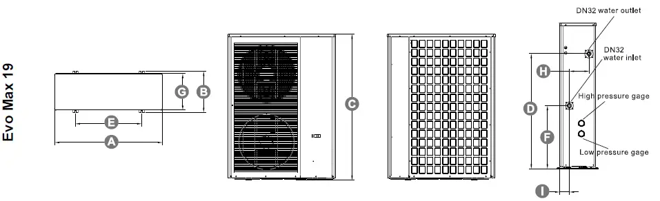
| Evo Max | A (L) | B (W) | C (H) | D | E | F | G | H | I |
| 19 | 1175 | 400 | 1605 | 1267 | 725 | 694 | 402 | 215 | 107 |
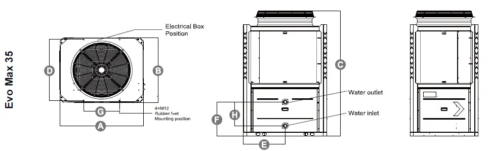
| Evo Max | A (L) | B (W) | C (H) | D | E | F | G | H |
| 35 | 1195 | 980 | 1900 | 925 | 598 | 517 | 516 | 360 |
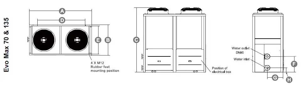
| Evo Max | A (L) | B (W) | C (H) | D | E | F | G | H | ||||||||
| 70 | 1930 | 1050 | 1980 | 1170 | 998 | 539 | 530 | 170 | ||||||||
| 135 | 2350 | 1150 | 2370 | 1590 | 1098 | 614 | 575 | 164 |
Safety Instructions
- Installation, repairs and maintenance of this unit must be performed by a qualified technician.
- Any wiring must comply with local electrical regulations.
- If any abnormal instances occur or a strange smells, the unit must be shut off by the power supply.
- Do not put fingers or objects into the fans or evaporator of the unit.
- The unit must be earthed to avoid any risk caused by insulation defects.
- No wiring must come into contact with the heat source or the rotating fan parts.
- The unit must be handled and lifted with appropriate equipment in correlation with the unit’s size and weight.
- Electrical power must be switched off before any work is started on the unit.
- Do not expose the unit to or install near any flammable gases.
- Ensure there is a circuit breaker for this unit.
- Copper and iron can not be used as a fuse.
- The unit is equipped with an over-load protection system. After a previous stoppage, the unit will not start for at least 3 minutes.
- If the supply cord is damaged, it must be replaced by the manufacturer, our service agent or a similarly qualified person in order to avoid a hazard.
- USE SUPPLY WIRES SUITABLE FOR 75℃.
- Caution: Single wall heat exchanger, not suitable for potable water connection.
Installation
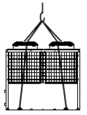
Transit
When transporting the unit, ensure the unit is kept standing upright. Laying the unit down may damage internal parts.
If the unit needs to be hung up (such as for lifting with a crane) use the special lifting hole (hook) on the base of the unit with an 8 metre cable. Ensure there is some kind of padding between the cable and the unit to prevent damage to the heat pump cabinet.
Location of Installation
The unit can be installed in any outdoor area which can carry the weight of heavy machinery, such as a terrace, rooftop, the ground etc.
- The location must have adequate ventilation and be free from strong winds.
- The installation location must be free from heat radiation and fire hazards.
- Ensure there are no obstacles near the air inlet and outlet of the heat pump.
- There must be a water channel around the heat pump to drain condensing water.
- Ensure that there is enough space around the unit for maintenance.
- The heat pump can be installed onto the concrete basement using expansion screws, or onto a steel frame with rubber feet which can be placed on the ground or rooftop. Ensure the unit is placed horizontally.
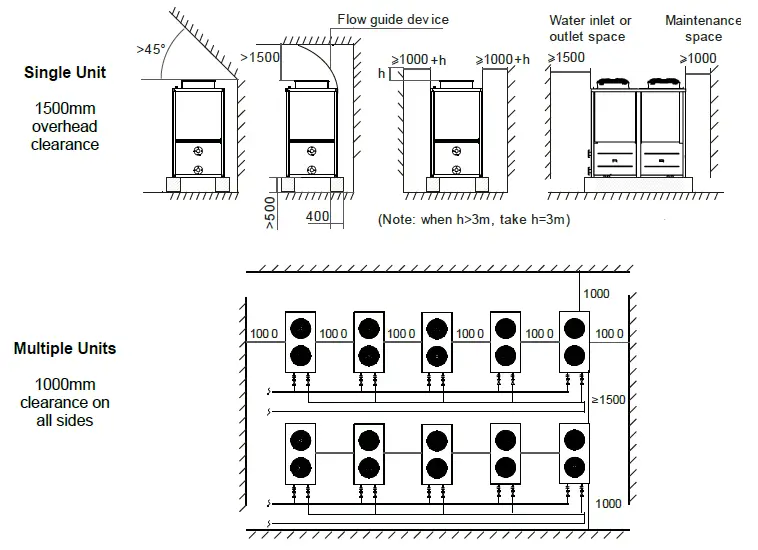
Airflow Clearances
Plumbing
- Try to reduce the resistance to the water from the piping.
- The piping must be clear and free from dirt and blockage. A water leakage test must be carried out to ensure that there is no water leaking before the installation can be made.
- The pipe must be tested by pressure separately. DO NOT test it together with the unit.
- There must be an expansion tank on the top point of the water loop, and the water level inside the tank must be at least 0.5meters higher than the top point of the water loop.
- The flow switch is installed inside of the heat pump, check to ensure that the wiring and action of the switch is normal and controlled by the controller.
- The connection between the heat pump and the construction is best to be of a flexible type to avoid vibration transfer. The support to the water pipe must be separate, but not rely on the heat pump unit.
- Try to avoid any air from being trapped inside the water pipe, there must be an air vent on the top point of the water loop.
- There must be a thermometer and pressure meter at the water inlet and outlet for easy inspection during running.
- There must be drainage on the low points of the water system, and there is already drainage on the chassis of the heat pump. The water in the system must be drained out during winter if the heat pump is not to be used.
Electrical Connection
- Open the panel and open the power line hole
- Thread the power line though the hole and connect it to the power line terminal. The three-core control line of the remote controller shall be plugged with the three-core signal line on the main board according to the wiring diagram.
- For an external water pump, thread the power line of the water pump through the hole and connect it to the water pump terminals.
- If an additional auxiliary heater is needed to be to be controlled by the heat pump controller, the relay (or power) of the aux-heather must be connected to the relevant output of the controller.
ATTENTION:
- The unit should use an independent power supply, see wiring in 8.4 Cable Specifications. Power supply voltage must be in line with the rated voltage.
- The power supply circuit must be equipped with an All-pole disconnect device and have at least 3mm contact opening distance.
- The wiring must be completed by a professional technician in accordance with the circuit diagram.
- Power supply circuit must have earth wire; the earth wire of power should be connected with an external earth wire safely. The external earth wire must be in order.
- The creepage protection device must be settled in accordance with the relevant national technical standards for electronic equipment.
- The power wire and signal wire should be neatly arranged. High voltage wires and low voltage wires must be separated and free from any interference. These wires must also be free from any pipes or valves on the unit.
- When all wiring is completed, the power should only be connected after a thorough double check.
Initial Start-Up
Prior To:
- Check the indoor unit, make sure that the pipe connection is done correctly and that the relevant valves are open.
- Check the water loop to ensure that there is enough water inside of the expansion tank, that the water supply is good and that the water loop has no air in it and is full of water. Make sure there in good insulation for the water pipe.
- Check the electrical wiring. Make sure that the power voltage is normal, the screws are fastened, the wiring is made in line with the diagram and the earthing is connected.
- Check that the heat pump, including all the screws and different parts are in good order. When the power is on, review the indicator on the controller to see if there is any failure indications. The gas gauge can be connected to the check valve to see the high pressure (or low pressure) of the system during trial running.
Trial Operation:
- Start the heat pump and check whether the water pump is running, if it is running normally there will be 0.2MPa on the water pressure meter.
- When the water pump runs for 1 minute, the compressor will start. Hear whether there is a strange sound coming from the compressor. If an abnormal sound occurs, please stop the unit and check the compressor. If the compressor runs well, look for the pressure meter of the refrigerant.
- Check whether the power input and running current is in line with the manual. If not stop the unit and check for why this may be occurring.
- Adjust the valves on the water loop to make sure that the hot (cool) water supply to each door is good and meets the requirement of heating (or cooling).
- Review whether the outlet water temperature is stable.
Operation
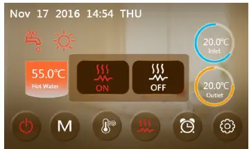
The Controller
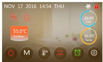
 | ON/OFF | Turn the unit on or off. When the unit is on, the button will be red. |
 | MODE | Switch modes |
 | TEMP. SETTING | Enter the temperature setting menu. |
 | FAST HEATING | Press this to begin rapid heating. |
 | TIMER | Set a unit on/off timer. When a timer is on, this icon will be green. |
 | SETUP | Check the unit status, time, factory parameters, temp. curve, timer & mute settings. |
 |  | ||
| FAULT | DEFROSTING | HOT WATER MODE | HEATING MODE |
| When an error occurs this icon will flash at the top right of the screen. Tap the icon to see a record of failures. | When this icon is shown the unit is in defrosting mode. | When this icon is shown the unit is in hot water mode. | When this icon is shown the unit is in heating mode. |
Operating Functions
Start-up & Shutdown
To turn the unit on or off, press ON/OFF button. The icon will be grey when the unit is off, and green when it is on.
Mode Switch
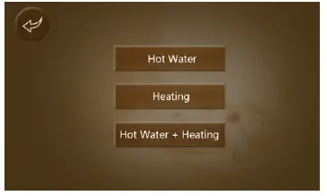
From the main menu there are five different operating modes that can be chosen from. Press MODE ![]() to select from the options:
to select from the options:
Hot Water, Heating, Cooling, Hot Water & Heating or Hot Water & Cooling
Note: If you have purchased a heating-only model (with no cooling functions) “cooling” mode will not appear.
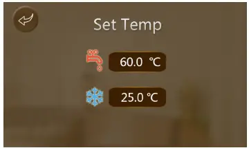
Setting the Target Temperature
Press the TEMP. SETTING ![]() button to change the set temperature values of heating and/or cooling mode.
button to change the set temperature values of heating and/or cooling mode.
Press the temperature value to alter the value, then press ‘Enter’ to save and return to the main menu.
Fast Heating Mode
While the unit is in heating mode, press the FAST HEATING ![]() button to enable the rapid heating function.
button to enable the rapid heating function.
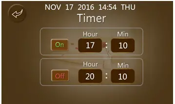
Setting a Timer
You can set a customised start-up and shutdown timer for your unit. Press the TIMER ![]() button on the main menu and enter your desired ‘ON’ & ‘OFF’ times.
button on the main menu and enter your desired ‘ON’ & ‘OFF’ times.
Press the On/Off button to the left of each time to toggle the start/end timers. When they are not on the button will be grey instead of coloured.
Example: The unit will turn on at 17:10 and shut down at 20:10.

Fault Interface
Press the FAULT ![]() icon on the main menu to display a record of all failures that have occurred.
icon on the main menu to display a record of all failures that have occurred.
After faults have been reviewed and corrected, press the top right ‘Clear’ button to wipe the records.
Colour Display Calibration
Keep clicking quickly at the blank area on any interface till you hear a long beep. You will then enter the calibration interface.
Click “+” to start calibration. When you hear the beep again, you will have finished calibration and can exit.
Troubleshooting
| Protect/fault | Fault Display | Reason | Elimination methods |
| Inlet Temp Sensor Fault | P01 | The temp. Sensor is broken or short circuit | Check or change the temp. sensor |
| Outlet Temp Sensor Fault | P02 | The temp. Sensor is broken or short circuit | Check or change the temp. sensor |
| Water Tank Temp Sensor | P03 | The temp. Sensor is broken or short circuit | Check or change the temp. sensor |
| AT Sensor Fault | P04 | The ambient temp. Sensor is broken or short circuit | Check or change the temp. sensor |
| Syst1:Coil temp1 Sensor | P153 | The temp. Sensor is broken or short circuit | Check or change the temp. sensor |
| Syst1:Coil temp2 Sensor | P154 | The temp. Sensor is broken or short circuit | Check or change the temp. sensor |
| Syst1:Suction temp Sensor | P17 | The temp. Sensor is broken or short circuit | Check or change the temp. sensor |
| Syst1:Antifreeze Sensor1(US) | P191 | The temp. Sensor is broken or short circuit | Check or change the temp. sensor |
| Syst1:Antifreeze Sensor2(US) | P193 | The temp. Sensor is broken or short circuit | Check or change the temp. sensor |
| Syst1:Antifreeze Sensor4(HSS) | P195 | The temp. Sensor is broken or short circuit | Check or change the temp. sensor |
| Syst1:Inlet Sensor(EVI) | P101 | The temp. Sensor is broken or short circuit | Check or change the temp. sensor |
| Syst1:Outlet Sensor(EVI) | P102 | The temp. Sensor is broken or short circuit | Check or change the temp. sensor |
| Syst1:Exhaust temp Sensor | P181 | The temp. Sensor is broken or short circuit | Check or change the temp. sensor |
| Syst1:Pressure Sensor fault | PP11 | The system 1 pressure Sensor is broken or short circuit | Check or change the pressure sensor or pressure |
| Syst2:Coil temp Sensor | P25 | The temp. Sensor is broken or short circuit | Check or change the temp. sensor |
| Syst2:Suction temp Sensor | P27 | The temp. Sensor is broken or short circuit | Check or change the temp. sensor |
| Syst2:Antifreeze Sensor1(US) | P291 | The temp. Sensor is broken or short circuit | Check or change the temp. sensor |
| Syst2:Antifreeze Sensor2(US) | P293 | The temp. Sensor is broken or short circuit | Check or change the temp. sensor |
| Syst2:Antifreeze Sensor1(HSS) | P292 | The temp. Sensor is broken or short circuit | Check or change the temp. sensor |
| Syst2:Antifreeze Sensor2(HSS) | P296 | The temp. Sensor is broken or short circuit | Check or change the temp. sensor |
| Syst2:Exhaust Temp Sensor | P281 | The temp. Sensor is broken or short circuit | Check or change the temp. sensor |
| Syst2:Pressure Sensor fault | PP21 | The system 2 pressure Sensor is broken or short circuit | Check or change the pressure sensor or pressure |
| Syst2:Inlet Sensor(EVI) | P201 | The temp. Sensor is broken or short circuit | Check or change the temp. sensor |
| Syst2:Outlet Sensor(EVI) | P202 | The temp. Sensor is broken or short circuit | Check or change the temp. sensor |
| Syst1:Exhaust Overtemp | P182 | The temp. Sensor is broken or short circuit | Check or change the temp. sensor |
| Syst2:Exhaust Overtemp | P282 | The temp. Sensor is broken or short circuit | Check or change the temp. sensor |
| Low ATProtection | TP | The ambient temp. is low | |
| Fan Motor1 Fault | F031 | 1. Motor is in locked-rotor state 2.The wire connection between DC-fan motor module and fan motor is in bad contact | 1. Change a new fan motor 2. Check the wire connection and make sure they are in good contact |
| Fan Motor2 Fault | F032 | 1. Motor is in locked-rotor state 2.The wire connection between DC-fan motor module and fan motor is in bad contact | 1. Change a new fan motor 2. Check the wire connection and make sure they are in good contact |
| Communication Fault (speed control module) | E081 | Speed control module and main | Check the communication connection |
| Communication Fault | E08 | Communication failure between wire controller and mainboard | Check the wire connection between remote wire controller and main board |
| Syst1:Comp Overcurrent | E101 | The compressor is overload | Check if system of compressor running normally |
| Syst2:Comp Overcurrent | E201 | The compressor is overload | Check if system of compressor running normally |
| Syst1: HP Protection | E11 | The high-pressure switch is broken | Check the pressure switch and cold circuit |
| Syst2: HP Protection | E21 | The high-pressure switch is broken | Check the pressure switch and cold circuit |
| Syst1: LP Protection | E12 | The high-pressure switch is broken | Check the pressure switch and cold circuit |
| Syst2: LP Protection | E22 | The high-pressure switch is broken | Check the pressure switch and cold circuit |
| Flow Switch Protection | E032 | No water/little water in water system | Check the pipe water flow and water pump |
| Aux Superheat Protection | E04 | Electric-heater protection switch is broken | Check to see if the electric heater has been running under the temperature over 150 for a long time |
| Prim Anti-freezing Prot | E19 | The ambient temp. is low | |
| Secondary Anti-freezing Prot | E29 | The ambient temp. is low | |
| Syst1:Antifreeze(US) | E171 | Use side water system temp. is low | 1. Check US water temp. or change temp. sensor 2.Check pipe water flow and whether water system is jammed or not |
| Syst2:Antifreeze(US) | E271 | Use side water system temp. is low | 1. Check US water temp. or change temp. sensor 2.Check pipe water flow and whether water system is jammed or not |
| Syst1:Antifreeze(HSS) | E172 | Heat side water system temp. is low | 1. Check HSS water temp. or change temp. sensor 2.Check pipe water flow and whether water system is jammed or not |
| Syst2:Antifreeze(HSS) | E272 | Heat side water system temp. is low | 1. Check HSS water temp. or change temp. sensor 2.Check pipe water flow and whether water system is jammed or not |
| Syst1:Exhaust Overtemp | E182 | The compressor is overload | Check whether the system of the compressor running normally |
| Syst2:Exhaust Overtemp | E282 | The compressor is overload | Check whether the system of the compressor running normally |
| Excess Water Temp Diff | E06 | Water flow is not enough and low pressure difference | Check pipe water flow & if water system is jammed |
Appendix
Parameter List
| Meaning | Default | Remarks |
| Cooling target temperature set point | 12°C | Adjustable |
| Heating the target temperature set point | 40°C | Adjustable |
| Hot Water target temperature set point | 55°C | Adjustable |
Cable Specifications
| Nameplate maximum current | Phase line (Single Phase) | Phase Line (Three Phase) | Earth line | MCB | Creepage Protector | Signal Line | |
| No more than 10A | 2 x 1.5mm2 | 3 x 1.5mm2 | 1.5mm2 | 20A |
30mA less than 0.1 sec |
n x 0.5mm2 | |
| 10~16A | 2 x 2.5mm2 | 3 x 2.5mm2 | 2.5mm2 | 32A | |||
| 16~25A | 2 x 4mm2 | 3 x 4mm2 | 4mm2 | 40A | |||
| 25~32A | 2 x 6mm2 | 3 x 6mm2 | 6mm2 | 40A | |||
| 32~40A | 2 x 10mm2 | 3 x 10mm2 | 10mm2 | 63A | |||
| 40~63A | 2 x 16mm2 | 3 x 16mm2 | 16mm2 | 80A | |||
| 63~75A | 2 x 25mm2 | 3 x 25mm2 | 25mm2 | 100A | |||
| 75~101A | 2 x 25mm2 | 3 x 25mm2 | 25mm2 | 125A | |||
| 101~123A | 2 x 35mm2 | 3 x 35mm2 | 35mm2 | 160A | |||
| 123~148A | 2 x 50mm2 | 3 x 50mm2 | 50mm2 | 225A | |||
| 148~186A | 2 x 70mm2 | 3 x 70mm2 | 70mm2 | 250A | |||
| 186~224A | 2 x 95mm2 | 3 x 95mm2 | 95mm2 | 280A | |||
Wire Control Interface Diagram
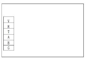
| Sign | Meaning |
| V | 12v (power +) |
| R | No Use |
| T | No Use |
| A | 485A |
| B | 485B |
| G | GND (power-) |
Controller Interface Diagram
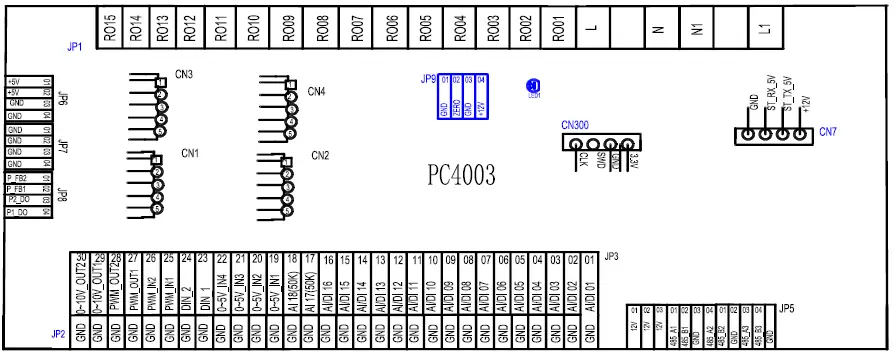
| No. | Sign | Meaning |
| 01 | AI/DI01 | Water input temperature |
| 02 | AI/DI02 | Water output temperature |
| 03 | AI/DI03 | System 1 coil temperature |
| 04 | AI/DI04 | Ambient temperature |
| 05 | AI/DI05 | System 1 suction temperature |
| 06 | AI/DI06 | System 1 antifreeze 1 temperature/ system 1 coil temperature 2 |
| 07 | AI/DI07 | System1 Antifreeze 2 Temperature |
| 08 | AI/DI08 | Water tank Temperature |
| 09 | AI/DI09 | System1 Antifreeze 4 Temperature |
| 10 | AI/DI10 | Temperature of the EVI inlet of system 1 |
| 11 | AI/DI11 | Temperature of the EVI outlet of system 1 |
| 12 | AI/DI12 | The high-pressure switch 1 |
| 13 | AI/DI13 | The low-pressure switch 1 |
| 14 | AI/DI14 | Water flow switch protection |
| 15 | AI/DI15 | Emergency switch output |
| 16 | AI/DI16 | Mode switch |
| 17 | AI17 (50K) | Overload switch of electric heater |
| 18 | AI18 (50k) | System Exhaust temperature 1 |
| 19 | 0~5V_IN1 | System 1 compressor current detection |
| 20 | 0~5V_IN2 | Water level sensor |
| 21 | 0~5V_IN3 | pressure sensor 1 |
| 22 | PWM_IN1 | System flow meter (reserved) |
| 23 | PWM_IN2 | No use |
| 24 | PWM_OUT1 | AC Fan control output |
| 25 | PWM_OUT2 | No use |
| 26 | 0~10V OUT1 | No use |
| 27 | 0~10V OUT2 | No use |
| 28 | +5V | 5V output |
| 29 | +12V | 12V output |
| 30 | CN1 | Communication ports on the expansion board |
| 31 | CN2 | Centralized control port |
| 32 | CN4 | Electronic expansion valve 1 |
| 33 | CN5 | Colour line controller |
| 34 | CN8 | Electronic expansion valve of EVI in system 1 |
| 35 | CN15 | DTU |
| 36 | RO11 | Electromagnetic three-way valve 2 |
| 37 | RO10 | Electromagnetic three-way valve 1 |
| 38 | RO09 | Hot water pump |
| 39 | RO08 | Alarm output |
| 40 | RO07 | AUX superheat |
| 41 | RO06 | 4-way valve |
| 42 | RO05 | Water pump |
| 43 | RO04 | Fan 2 / Fan low speed |
| 44 | RO03 | Fan 1 / Fan high speed |
| 45 | RO02 | Compressor 2 |
| 46 | RO01 | Compressor 1 |
Maintenance
DO I NEED TO GET MY UNIT SERVICED?
It is recommended that you get your EvoHeat unit serviced once a year by your local certified air conditioning or refrigeration technician. If your unit is located in a coastal area, more frequent maintenance may be necessary. During the service, they will check the operational pressures of the refrigeration system and give the unit and fins a good clean to ensure maximum performance.
DO WE HAVE RECOMMENDED SERVICE AGENTS?
EvoHeat have a large database of recommended service agents. Please contact EvoHeat tech support on 1300 859 933 for your local service agent details.
SHOULD I CHECK MY UNIT REGULARLY?
We recommend you check your unit regularly to avoid potential issues and damage to your heat pump.
Check the water inlet/outlets often for leaks. You should avoid the condition of no water or air entering into the system, as this will influence unit’s performance and reliability.
The area around the unit should be dry, clean and well ventilated. Make sure there is nothing blocking the airflow of the heater e.g. Leaf litter. Clean the heat exchanger every few months to keep a good heat exchange rate and save energy.
WHAT SHOULD I BE CHECKING REGULARLY?
You should discharge the water at the bottom of the water pump if the unit will not be used for an extended period. Discharge all water in the water pump and water system so that freezing of the water in the pump or water system does not occur. Check the unit thoroughly and fill the system with water fully before using it for the first time after a period of time.
Check the power supply and cable connection often, should the unit begin to operate abnormally, switch it off and contact the qualified technician
Clean the water filter periodically to maintain good water quality. Lack of water and dirty water can damage the unit. The heat pump will start the water every 72 hours when it is not running to avoid freezing.
The water loop of the heat pump MUST be protected from freezing in winter. Do not shut off the power supply to the heat pump in winter. When the air temperature is below 0°C, if the inlet water temperature is above 2°C and below 4°C the water pump will begin freezing protection. If the inlet water is lower than 2°C, the heat pump will begin heating.
Warranty
Refer to the EvoHeat website for warranty details
- Australia: https://evoheat.com.au/warranty-terms/
- South East Asia: http://evoheat.com.sg/warranty/
- Warranty terms are from date of purchase.
- This warranty excludes any defect or injury caused by or resulting from misuse, abuse, neglect, accidental damage, improper voltage, vermin infestation, incompetent installation, any fault not attributable to faulty manufacture or parts, any modifications which affect the reliability or performance of the unit.
- This warranty does not cover the following:
- Natural Disasters (hail, lightening, flood, fire etc.)
- Rust or damage to paintwork caused by a corrosive atmosphere
- When serviced by an unauthorized person without the permission of Evo Industries
- When a unit is installed by an unqualified person
- Where a unit is incorrectly installed
- When failure occurs due to improper or faulty installation
- Failure due to improper maintenance (refer Operating Instructions)
- ‘No Fault Found’ service calls where the perceived problem is explained within the
- Costs associated with delivery, handling, freighting, or damage to the product in transit.
- If warranty service is required, you should:
- contact Evo Industries Australia on 1300 859 933 or via our Contact page on our web site
- provide a copy of your receipt as proof of purchase
- have completed the online Warranty Registration Form
- Onsite technical service is available within the normal operating area of your Evo Authorised Service Agents. Service outside this area will incur a traveling fee.
- Unless otherwise specified to the purchaser, the benefits conferred by this express warranty and additional to all other conditions, warranties, rights and remedies expressed or implied by the Trade Practices Act 1974 and similar consumer protection provisions contained in legislation of the States and Territories and all other obligations and liabilities on the part of the manufacturer or supplier and nothing contained herein shall restrict or modify such rights, remedies, obligations or liabilities.
REGISTER YOUR WARRANTY
EvoHeat highly recommend customers complete their warranty details online to ensure efficient warranty claim processing.
To register your warranty, scan our QR Code or head to our website and fill in the Warranty Registration Form: https://evoheat.com.au/warranty-registration/

[email protected]
1300 859 933
www.evoheat.com.au


