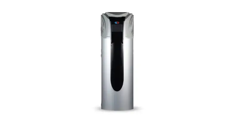
EVOHEAT CAMMAND-i Commercial Hot Water and Space Heat Pump
Introduction
This manual contains information relating to the installation, troubleshooting, operation, and maintenance of this EvoHeat unit. Instructions in this manual must always be followed. Failure to comply with these recommendations will invalidate the warranty. Should you have any questions or require technical support, call the EvoHeat office on 1300 859 933 to speak to our team.
The data and information contained in this manual is correct at the time of publishing and is subject to change without notice. For the most up to date manual, contact EvoHeat directly.
Designed with the latest inverter technology, the Evo Command-i is the smarter choice for commercial space and water heating and cooling.
The Evo Command-i Series is ideal for commercial and industrial water and space heating applications, including: hotels, resort, commercial buildings, sporting and leisure facilities, industrial liquid heating and chilling applications.
| TECHNICAL DATA | Command-i 40 | Command-i 90 | Command-i 210 | |
| Hot Water Capacity | kW | 40 | 90 | 210 |
| Water Outlet | L/h | 860 | 1930 | 4503 |
| Heating Input Power | kW | 8.5 | 19.70 | 45.7 |
| C.O.P | / | 4.7 | 4.57 | 4.6 |
| Building Heating A | kW | 13~45 | 16~95 | 74.8~215 |
| Heating Input Power | kW | 4.7~15.3 | 9.5~28.9 | 18.8~75.4 |
| C.O.P | / | 2.3 | 2.43 | 2.42 |
| Building Cooling | kW | 9.4~33 | 20~74.3 | 46.6~132 |
| Cooling Input Power | kW | 3.9~15.8 | 8.70~25.65 | 16.5~56.2 |
| EER | / | 2.02~2.73 | 2.52~2.95 | 2.35~2.82 |
| Heating IPLV | / | 3.25 | 3.2 | |
| Power Supply | / | 380-415/3/50 | 380-415/3/50 | 380-415/3/50 |
| Max Input Current | A | 36.8 | 51 | 135 |
| Water Connection | / | DN40 | DN65 | DN80 |
| Water Flow | L/min | 115 | 172 | 602 |
| Water Pressure Drop | kPa | 75 | 70 | 100 |
| Noise | dB(A) | 56~65 | 56~69 | 63~72 |
| Net Weight | kg | 468 | 733 | 1250 |
| Dimensions (L/W/H) | mm | 1195/980/1900 | 2170/1150/2130 | 2481/1331/2367 |
Hot water conditions: ambient temp. (DB/WB): 20°C/15°C, water circulation is from 15°C to 55°C Building heating A: ambient temp. (DB/WB): 7°C/6°C, water temp (in/out) 40/45°C Building cooling: ambient temp. (DB/WB): 35°C/24°C, water temp (in/out) 12/7°C
Dimensions
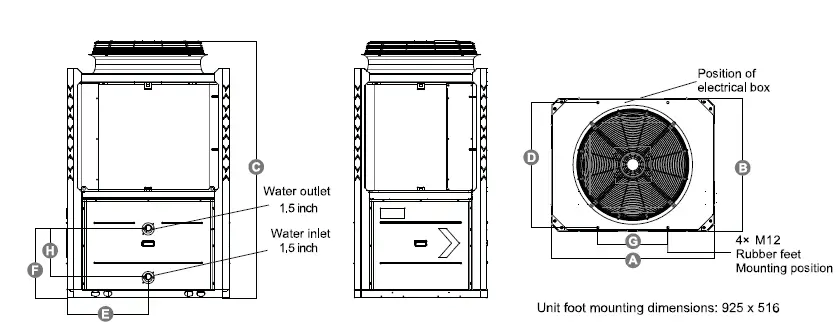
| Command-i | A (L) | B (W) | C (H) | D | E | F | G | H |
| 40 | 1195 | 980 | 1900 | 925 | 598 | 517 | 516 | 360 |
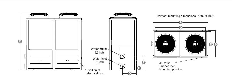
| Command-i | A (L) | B (W) | C (H) | D | E | F | G | H |
| 90 | 2170 | 1150 | 2130 | 1590 | 1098 | 614 | 575 | 164 |
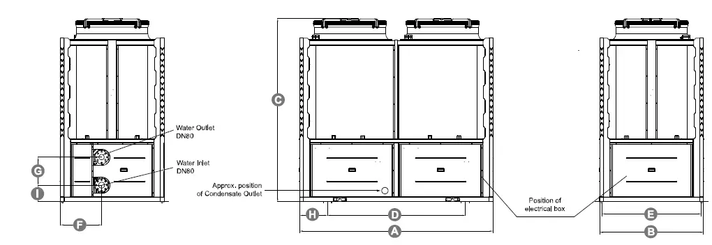
| Command-i | A (L) | B (W) | C (H) | D | E | F | G | H | I |
| 210 | 2481 | 1331 | 2367 | 1770 | 1278 | 530 | 360 | 356 | 215 |
Safety Instructions
Installation, repair, or relocations must only be done by a fully qualified technician. If done incorrectly there is a number of hazards that can occur including fire, electric shock, water leakage and injury.
- When an abnormality (smell of burning, etc.) occurs, stop the unit and disconnect the power or turn off the breaker. If the unit continues to be operated in an abnormal condition, it may cause a fire or hazards.
- Do not insert fingers or objects into the fans or evaporator of the unit.
- Installation, repair or relocations must be done by a fully qualified person and not by the customer. If done incorrectly it may cause fire, electric shock, water leakage and other hazards.
- For unit cleaning or maintenance, switch off and disconnect the power of the unit.
- Do not spray insecticides or flammable sprays around the unit, it may cause a fire or damage the unit’s cabinet.
- Do not install the unit near flammable gas or spray flammable substances near it.
- Ensure the heat pump is installed on a strong and stable platform.
- A circuit breaker must be installed for the unit.
- Use supply wires suitable for 75C.
- The heat pump located inside the unit is equipped with an over-load protection system. It does not allow for the unit to start for at least 3 minutes from a previous stoppage.
- Copper or iron must not be used as a fuse. An electrician must use the correct fuse for the heat pump.
- Make sure that the unit and power connection have good earthing.
- If the supply cord is damaged, it must be replaced by the manufacturer, our service agent or a similarly qualified person in order to avoid a hazard.
- Caution: Single wall heat exchanger, not suitable for potable water connection.
Installation
System Installation
When transporting the unit ensure that it is kept upright, lying the unit down may damage inner parts of the unit.
Upon receiving the unit, check the packaging for any obvious signs of damage. Inform EvoHeat immediately if there is any evidence of rough handling.
Location of Installation
The heat pump can be installed onto the concrete basement by using expansion screws, or onto a steel frame with rubber feet which can be placed on the ground or the roof. Ensure that the unit is placed horizontally.
- The unit can be installed in any place outdoors which will be able to support the weight of a heavy unit such as a terrace, roof, the ground and any other places deemed suitable.
- The location must have good ventilation.
- The location must be free from heat radiation and other fire hazards.
- A pall is needed in winter to protect the unit from snow.
- There must be no obstacles near the inlet and outlet of the unit.
- The installation location must be protected from strong winds or air.
- There must be a water channel around the heat pump to drain condensing water.
- Leave enough space around the unit for maintenance.
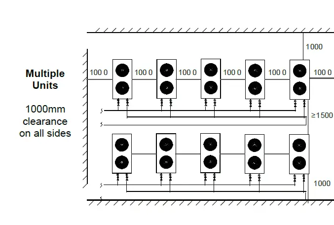
Airflow Clearances
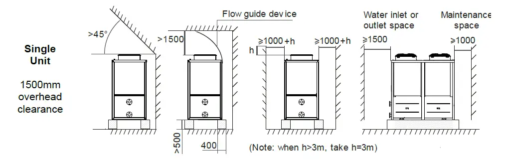
Note:
- Do not cover the air outlet of the unit.
- If there is a barrier above the unit, keep it at least 3000mm above the unit.
- If there are objects stacked around the unit, their height should be at least 400mm lower than the top of the unit.
- When installed in a small room, measures should be taken to prevent leakage of the refrigerant. Once leakage volume exceeds the limit concentration, it may cause suffocation. Contact EvoHeat for specific measures.
Plumbing
When the water pipe is connected:
- Try to reduce the resistance to the water from the piping.
- The piping must be clear and free from dirt and blockage. A water leakage test must be carried out to ensure that there is no water leaking before the installation can be made.
- The pipe must be tested by pressure separately. DO NOT test it together with the unit.
- There must be an expansion tank on the top point of the water loop, and the water level inside the tank must be at least 0.5meters higher than the top point of the water loop.
- The flow switch is installed inside of the heat pump, check to ensure that the wiring and action of the switch is normal and controlled by the controller.
- Try to avoid any air from being trapped inside the water pipe, there must be an air vent on the top point of the water loop.
- There must be a thermometer and pressure meter at the water inlet and outlet for easy inspection during running.
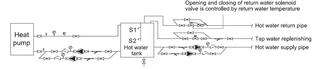
Hot Water Circuit Diagram
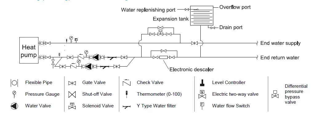
Heating (Cooling) Water Circuit Diagram
Electrical Connection
Always use a qualified Electrician to perform any electrical work. A licensed electrician must read the information before connecting.
- Open the front panel and open the power supply access.
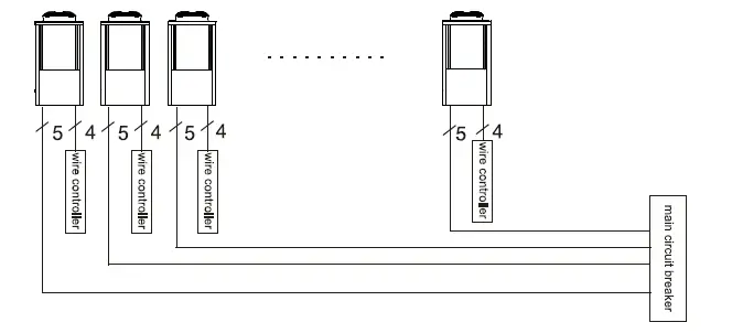
- The power supply must go through the wire access and be connected to the power supply terminals in the controlling box. Then connect the 3-signal wire plugs of the wire controller and main controller.
- If an external water pump is required, please insert the power supply wire into the wire access and connect it to the water pump terminals.
- If an additional auxiliary heater is needed to be controlled by the heat pump controller, the relay (or power) of the aux-heater must be connected to the relevant output of the controller.
Cable & Switch
- The unit should use an independent power supply, wiring as required for Table 6.1. Power supply voltage must be in line with the rated voltage.
- Power supply circuit must be equipped with an All-pole disconnect device and have at least 3mm contact opening distance.
- Wiring is only to be performed with a professional technician in accordance with the circuit diagram.
- The Power supply circuit must have an earth wire. The earth wire of the power should be connected with the external earth wire safely. The external earth wire must be in order correctly.
Initial Start-Up
Pre-Inspection
- Check the indoor unit, make sure that the pipe connection is done correctly, and the relevant valves are open.
- Check the water loop to ensure that the water inside of the expansion tank is filled to an appropriate level, and the water supply is working, and the water loop is full of water and free of trapped air. Make sure there is good insulation for the water pipe.
- Check the electrical wiring. Make sure that the power voltage is normal, the screws are fastened, the wiring is made in line with the diagram and that the earthing is connected.
- Check that the heat pump includes all the screws and components, and that they are in good order. When powering the unit on, review the indicator on the controller to see if there is any indication of failure. The gas gauge can be connected to the check valve to see the high pressure (or low pressure) of the system during trial running.
Trial Running
- Start the heat pump by pressing the ‘POWER’ button on the controller. Check whether the water pump is running, if it runs normally there will be 0.2MPa on the water pressure meter.
- When the water pump has ran for a minute, the compressor will start. Listen for any strange sounds from the compressor, if an abnormal sound occurs please stop the unit and check the compressor. If the compressor runs well, look for the pressure meter of the refrigerant.
- Check whether the power input and running current is in line with the manual. If not, stop and check.
- Adjust the valves on the water loop to make sure that the hot (cool) water supply to each door is good and meets the requirements of heating (or cooling).
- Review whether the outlet water temperature is stable.
- The parameters of the controller are set by the factory, the user must change these themselves.
Operation
The Controller
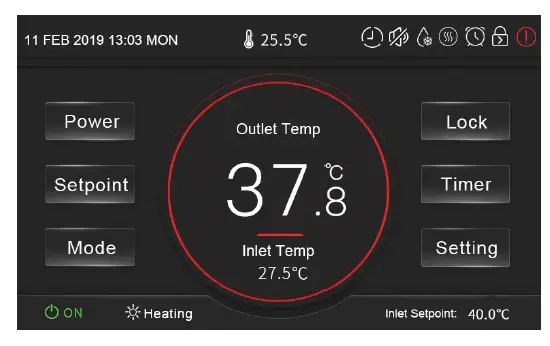
- Power
Turn the unit on or off - Setpoint
Set the target temperature - Mode
Select heating or cooling mode - Lock
Lock or unlock the screen - Timer
Enter timer setting menu (Temp Timer, Power Timer & Mute Timer) - Setting
Enter function menu (Status, Parameter, Failures & Time)
Target temperature of inlet water
Unit’s set date & time - Display Circle
Blue: Cooling mode, Red: Heating Mode, Grey: Off
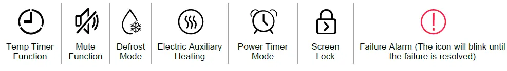
Icons will appear at the top right of the screen indicating certain functions that are enabled, or if there has been an error with the system.
Operating Functions
On/Off
From the main menu, simply press the ‘Power’ button to turn the unit on or off.
Mode Selection
From the main menu, pressing the ‘Mode’ button will allow you to select either heating or cooling mode. The status bar (bottom of the screen) will display the unit’s current operating state.
The display circle will appear as red for heating, or blue for cooling. If the unit is off, it will simply be grey.
Setting the Target Temperature
To adjust the target temperature value, first choose a running mode (heating or cooling), then press the ‘Setpoint’ button to enter the parameter setting screen.
Enter the required parameter according to the effective range which is displayed at the bottom of the screen.
Locking the Screen
From the main menu, press the ‘Lock’ button to lock the controller screen and prevent unauthorised people accessing the controls.
When the screen is locked a small lock symbol will appear on the top right of the main menu.
To unlock the screen, press the ‘Lock’ button again and enter the password 22 which will unlock the screen and remove the lock symbol.
Setting a Timer
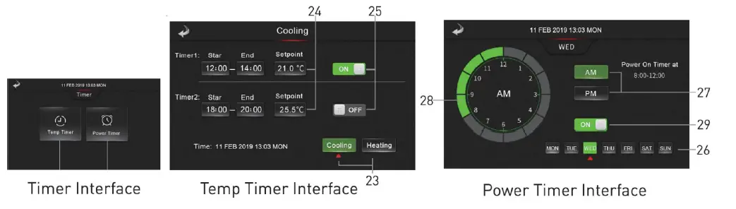
After pressing the ‘Timer button from the main interface, select from Temp Timer or Power Timer.
Temperature Timers
This function enabled time-sharing temperature control, which is two segments of staggered peak temperature control, and allows the target temperature of two segments of different time periods to be set according to different modes.
Press (23) to select from cooling or heating mode, then enter the start time, ending time and the target temperature setpoint value (24). Press (25) to enable or disable the settings.
Power Timer
This function allows you to set the opening time of the unit for each day of the week.
Press (26) to select the day of the week, then (27) to select AM or PM, after this press (28) to select the time, and finally select (29) to enable or turn off the setting.
Mute Timer
From the Timer menu, then press the Mute Timer button. Enter the start and end for the timer, then press the on/off button to enable or disable the function. When this function is enabled, a mute icon will appear on the main screen.
Note*: If the unit does not have the mute timer option, the function is not available.
Settings
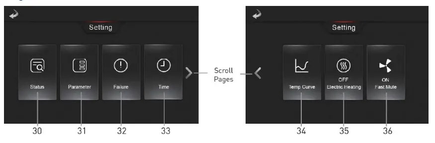
After pressing the ‘Setting’ button on the main menu, you can select from a range of functions.
Status
Press Status (30) to choose from Running Status or Unit Status.
Running Status
See below image.
Unit Status
Enter the password 22 to inquire the unit status parameter. Press one of the 4 buttons to inquire relevant parameters.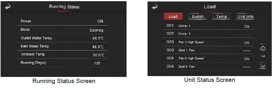
Parameters
After pressing the parameter button (31) from the settings menu, enter the password 22 to jump to the Installer Parameter interface for inquiring about relevant parameters.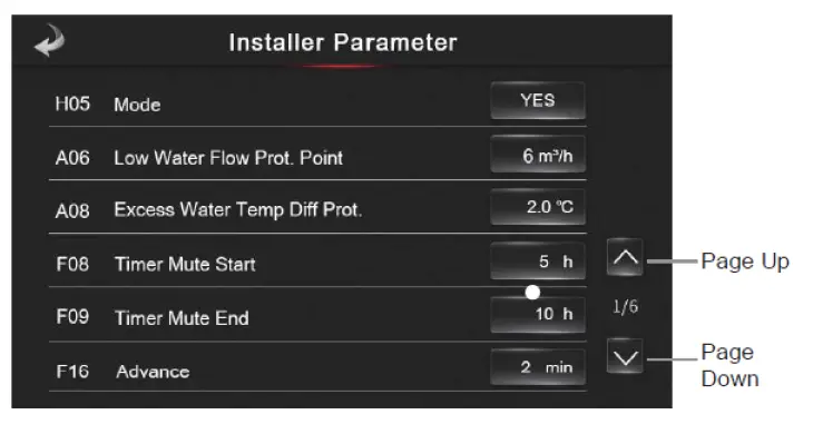
Temperature Curve
Press (34) to view the inlet/outlet temperature curve.
- This curve function records the water inlet outlet temperature.
- Temperature data is collected every 5 minutes, and the 12 sets of temperature data are saved every hour. Timekeeping is made from the latest data saving. If the power is disrupted before all 12 data sets have been collected the data will not be saved.
- Only curve for the electricity status is recorded, the outage status will not be saved.
- The value of the abscissa indicates the time from the point on the curve to the current time point. The leftmost point on the first page (0 on the abscissa is the latest temperature record).
- Temperature curve record is provided with power off memory function; in the case of a disturbed curve recording and display, when the unit is next powered on the wire controller will automatically clear the history curve record and the curve recording function will restore to a normal state.
Electric Heating
In the settings menu, the Electric Heating option will display as ‘OFF Electric Heating’. Make sure that the unit is firstly in heating mode, then press the electric heating button to head to its interface. Click the button to turn it on to activate the electric auxiliary heating mode. Turn off the function my tapping the button again.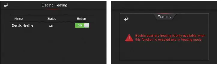
Fast Mute
The button will initially display as ‘OFF Fast Mute’ or ‘ON Fast Mute’. Press the button to enable/disable this function.
Display Calibration
Enter the Unit status menu in the following order (see 5.7.1 Status for password):
Main Interface → Setting → Status → Unit Status
Click the screen in the bottom left corner over 10 times within 4 seconds to bring up the display calibration interface. Click the blank squares to check whether there are bad spots within the screen. Green spots are normal.
To exit, click the screen in the bottom right corner.
Troubleshooting
| Protect/Fault | Fault Display | Reason | Elimination Methods |
| Communication Fault | E08 | Abnormal communication between wire controller and the main board | Inspect whether the wire controller, the main board and the connection thereof are reliable |
| The Wire Controller Does Not Match The Mainboard | E084 | ||
| DC Fan Board 1 Communication Fault | E081 | Communication of the speed regulation module 1 with main board is abnormal | “Check the speed regulation module 1 and the main board and if their connections are normal and reliable.” |
| Syst1: High Pressure Prot. | E11 | The high-voltage switch of the system is disconnected | Inspect System 1 voltage switch and refrigerating circuit for any failure |
| Syst2: High Pressure Prot. | E21 | The high-voltage switch of the system is disconnected | Inspect System 2 voltage switch and refrigerating circuit for any failure |
| Syst1: Low Pressure Prot. | E12 | The low-voltage switch of the system is disconnected | Inspect System 1 voltage switch and refrigerating circuit for any failure |
| Syst2: Low Pressure Prot. | E22 | The low-voltage switch of the system is disconnected | Inspect System 2 voltage switch and refrigerating circuit for any failure |
| Water Flow Switch Prot. | E032 | The water system has no or only few water | Inspect whether the water flow of the water pipe conforms to related requirements and check the water pump for any damages |
| Electric Heater Overload Prot. | E04 | Electric heating overheat protection switch is disconnected | Inspect whether the electric heating is under operation condition of over 150℃ for a long time |
| Primary Antifreezing Prot. In Winter | E19 | Excessively low environment temperature | |
| Secondary Antifreezing Prot. in Winter | E29 | Excessively low environment temperature | |
| Syst1: User Side Antifreezing Prot. | E171 | The water flow of the system is insufficient | Inspect whether the water flow of the water pipe conforms to related requirements and check the water pump for any blockage |
| Syst2: User Side Antifreezing Prot. |
E271 |
The water flow of the system is insufficient | Inspect whether the water flow of the water pipe conforms to related requirements and check the water pump for any blockage |
| Water(Out) High Temp Prot. | E065 | Excessively high water outlet temperature | |
| Fan 1 Thermal Overload Prot. | E103 | Fan 1 thermal overload | Check if fan 1 is running normally |
| Fan 2 Thermal Overload Prot. | E203 | Fan 2 thermal overload | Check if fan 2 is running normally |
| Syst1: Exhaust Air High Temp Prot. | P182 | The system compressor is overloaded | Inspect whether the operation of System 1 compressor is normal |
| Syst2: Exhaust Air High Temp Prot. | P282 | The system compressor is overloaded | Inspect whether the operation of System 2 compressor is normal |
| Water In/Out Large Temp Diff Prot. | E06 | The water flow of the system is insufficient, the pressure difference of the water system is small | Inspect whether the water flow of the water pipe conforms to related requirements and check the water pump for any blockage |
| Water(Out) Low Temp Prot. | E071 | Excessively low water outlet temperature | |
| Low Water Flow Prot. | E035 | The system has no water or too low volume of water | Check if the water flow of water pipe meets the requirements and if the water pump is damaged. |
| Syst1:Refrigerant Leakage Abnormal | E131 | System 1 refrigerant leakage | Check if the refrigerant in the system leaks |
| Syst2: Refrigerant Leakage Abnormal | E231 | System 2 refrigerant leakage | Check if the refrigerant in the system leaks |
| Syst1: 4-Way Valve Abnormal Switch | E121 | SYS1 four-way valve switching failed | Check if the four-way valve commutation state is the desired state |
| Syst2: 4-Way Valve Abnormal Switch | E221 | SYS2 four-way valve switching failed | Check if the four-way valve commutation state is the desired state |
| Syst1: Low Pressure Prot. 3+ | E12 | The low-voltage switch of the system is disconnected | Inspect System 1 voltage switch and refrigerating circuit for any failure |
| Syst2: Low Pressure Prot. 3+ | E22 | The low-voltage switch of the system is disconnected | Inspect System 2 voltage switch and refrigerating circuit for any failure |
| Water Flow Switch Prot. 3+ | E032 | The water system has no or only few water | Inspect whether the water flow of the water pipe conforms to related requirements and check the water pump for any damages |
| Electric Heater Overload Prot. 3+ | E04 | Electric heating overheat protection switch is disconnected | Inspect whether the electric heating is under operation condition of over 150℃ for a long time |
| Syst1: User Side Antifreezing Prot. 3+ | E171 | The water flow of the system is insufficient | Inspect whether the water flow of the water pipe conforms to related requirements and check the water pump for any blockage |
| Syst2: User Side Antifreezing Prot. 3+ | E271 | The water flow of the system is insufficient | Inspect whether the water flow of the water pipe conforms to related requirements and check the water pump for any blockage |
| Water(Out) High Temp Prot. 3+ | E065 | Excessively high water outlet temperature | |
| Low Water Flow Prot. 3+ | E035 | The system has no water or too low volume of water | Check if the water flow of water pipe meets the requirements and if the water pump is damaged. |
| Syst1: Exhaust Air High Temp Prot. 3+ | P182 | The system compressor is overloaded | Inspect whether the operation of System 1 compressor is normal |
| Syst2: Exhaust Air High Temp Prot. 3+ | P282 | The system compressor is overloaded | Inspect whether the operation of System 2 compressor is normal |
| Water In/Out Large Temp Diff Prot. 3+ | E06 | The water flow of the system is insufficient, the pressure difference of the water system is small | Inspect whether the water flow of the water pipe conforms to related requirements and check the water pump for any blockage |
| Water(Out) Low Temp Prot. 3+ | E071 | Excessively low water outlet temperature | |
| Water In Sensor Fault | P01 | The temperature sensor is open or short circuited | Check and replace inlet water temperature sensor |
| Water Out Sensor Fault | P02 | The temperature sensor is open or short circuited | Check and replace outlet water temperature sensor |
| Syst1: Coil Temp Sensor1 Fault | P150 | The temperature sensor is open or short circuited | Check and replace the system 1 coil 1 temperature sensor |
| AT Sensor Fault | P04 | The temperature sensor is open or short circuited | Check and replace the ambient temperature sensor |
| Syst1: Suction Temp Sensor Fault | P17 | The temperature sensor is open or short circuited | Check and replace the system 1 return air temperature sensor |
| Syst1: User Side Antifreezing 1 Sensor Fault | P191 | The temperature sensor is open or short circuited | Check and replace the system 1 use side antifreeze 1 temperature sensor |
| Syst2:Coil Temp Sensor1 Fault | P250 | The temperature sensor is open or short circuited | Check and replace the system 2 coil 1 temperature sensor |
| Syst1: Coil(Out) Temp Sensor Fault | P152 | The temperature sensor is open or short circuited | Check and replace the system 1 coil outlet temperature sensor |
| Syst2: Coil(Out) Temp Sensor Fault | P252 | The temperature sensor is open or short circuited | Check and replace the system 2 coil outlet temperature sensor |
| Syst1: EVI(In) Temp Sensor Fault | P101 | The temperature sensor is open or short circuited | Check and replace the system 1 EVI inlet temperature sensor |
| Syst1: EVI(Out) Temp Sensor Fault | P102 | The temperature sensor is open or short circuited | Check and replace the system 1 EVI outlet temperature sensor |
| Syst1: Exhaust Air Temp Sensor Fault | P181 | The temperature sensor is open or short circuited | Check and replace the system 1 exhaust temperature sensor |
| Water Level Sensor Fault | E036 | Open circuit or short circuit of the water level sensor | Inspect and replace water level sensor |
| Syst1: Low Pressure Sensor Fault | PP11 | The sensor is open or short circuited | Check and replace the system 1 low pressure sensor |
| Syst2: Suction Temp Sensor Fault | P27 | The temperature sensor is open or short circuited | Check and replace the system 2 return air temperature sensor |
| Syst2: User Side Antifreezing 1 Sensor Fault | P291 | Temperature sensor fault | Check if the temperature sensor is working properly |
| Syst1: High Pressure Sensor Fault | PP12 | The sensor is open or short circuited | Check and replace the system 1 high pressure sensor |
| Syst2: High Pressure Sensor Fault | PP22 | The sensor is open or short circuited | Check and replace the system 2 high pressure sensor |
| Syst2: Exhaust Air Temp Sensor Fault | P281 | Open circuit or short circuit of the temperature sensor | Inspect and replace System 2 exhaust temperature sensor |
| Syst2: Low Pressure Sensor Fault | PP21 | Open circuit or short circuit of the sensor | Inspect and replace System 2 low-voltage sensor |
| Water Tank Temp Fault | P03 | Open circuit or short circuit of the temperature sensor | Inspect and replace water tank temperature sensor |
| Syst2: EVI(In) Temp Sensor Fault | P201 | Open circuit or short circuit of the temperature sensor | Inspect and replace System 2 enthalpy inlet temperature sensor |
| Syst2: EVI(Out) Temp Sensor Fault | P202 | Open circuit or short circuit of the temperature sensor | Inspect and replace System 2 enthalpy outlet temperature sensor |
| Low AT Power-Off Prot. | TP | Excessively low environment temperature | |
| Syst1: Coil Temp Sensor2 Fault | P154 | The temperature sensor is open or short circuited | Check and replace the system 1 coil 2 temperature sensor |
| DC Fan Board 2 Communication Fault | E082 | Communication of the speed regulation module 2 with main board is abnormal | Check the speed regulation module 2 and the main board and if their connections are normal and reliable. |
| Syst2: Coil Temp Sensor2 Fault | P254 | The temperature sensor is open or short circuited | Check and replace the system 2 coil 2 temperature sensor |
| Syst1: Comp. Communication Fault | F151 | Communication failure with system 1 compressor drive board | 1. Check if the communication line is normal; 2. Check if the system 1 compressor drive board is normal |
| Syst1: Comp. Start Fault | F152 | System 1 compressor failed to start | 1. Check if the compressor line is normal; |
| 2. Check if the system 1 compressor is blocked | |||
| Syst1: Start IPM Prot. | F153 | System 1 compressor starting current is too large | 1. Check if the starting high pressure is excessive; 2. Check if the system 1 compressor is blocked |
| Syst1: Running IPM Prot. | F154 | System 1 compressor running current is too large | Check if the pressure ratio is too high |
| Syst1: Comp. Overcurrent Prot. | F156 | System 1 compressor running current is too large | Check if the pressure ratio is too high |
| Comp. 1 IPM Over-Temp. Prot. | F155 | System 1 compressor drive board has poor heat dissipation | Check if there is a gap in the installation of the fluorine-cooled heat sink |
| Press 1 Bus Over Voltage Prot. | F157 | Voltage is too high | Check if the input voltage is higher than 480V |
| Press 1 Bus Under Voltage Prot. | F158 | Voltage is too low | Check if the input voltage is lower than 250V |
| Syst2: Comp. Communication Fault | F251 | Communication failure with system 2 compressor drive board | 1. Check if the communication line is normal; 2. Check if the system 2 compressor drive board is normal |
| Syst2: Comp. Start Fault | F252 | System 2 compressor failed to start | 1. Check if the compressor line is normal; 2. Check if the system 2 compressor rotor is locked |
| Syst2: Start IPM Prot. | F253 | System 2 compressor starting current is too large | 1. Check if the starting high pressure is excessive; 2. Check if the system 1 compressor is blocked |
| Syst2: Running IPM Prot. | F254 | System 2 compressor running current is too large | Check if the pressure ratio is too high |
| Syst2: Comp. Overcurrent Prot. | F256 | System 2 compressor running current is too large | Check if the pressure ratio is too high |
| Press 2 IPM Over-Temp Prot. | F255 | System 2 compressor drive board has poor heat dissipation | Check if there is a gap in the installation of the fluorine-cooled heat sink |
| Press 2 Bus Over Voltage Prot. | F257 | Voltage is too high | Check if the input voltage is higher than 480V |
| Press 2 Bus Under Voltage Prot. | F258 | Voltage is too low | Check if the input voltage is lower than 250V |
| Fan 1 Phase Loss Prot. | F101 | System 1 fan failed to start | Check if the system 1 fan line is normal |
| Fan 1 Zero Speed Prot. | F102 | System 1 fan failed to start | Check if the system 1 fan rotor is locked |
| Fan 1 Start IPM Prot. | F103 | System 1 fan starting current is too large | Check if the system 1 fan rotor is locked |
| Fan 1 Running IPM Prot. | F104 | System 1 fan running current is too large | Check if the system 1 fan rotor is locked |
| Fan 1 Overcurrent Prot. | F105 | System 1 fan running current is too large | Check if the system 1 fan rotor is locked |
| Fan 1 Over-Temp Prot. | F106 | System 1 fan drive board has poor heat dissipation | Check the heat dissipation condition |
| Fan 1 Bus Over Voltage Prot. | F107 | Voltage is too high | Check if the input voltage is higher than 480V |
| Fan 1 Bus Under Voltage Prot. | F108 | Voltage is too low | Check if the input voltage is lower than 250V |
| Fan 2 Output Phase Loss Prot. | F201 | System 2 fan failed to start | Check if the system 2 fan line is normal |
| Fan 2 Output Zero Speed Prot. | F202 | System 2 fan failed to start | Check if the system 2 fan rotor is locked |
| Fan 2 Start IPM Prot. | F203 | System 2 fan starting current is too large | Check if the system 2 fan rotor is locked |
| Fan 2 Running IPM Prot. | F204 | System 2 fan running current is too large | Check if the system 2 fan rotor is locked |
| Fan 2 Overcurrent Prot. | F205 | System 2 fan running current is too large | Check if the system 2 fan rotor is locked |
| Fan 2 Over-Temp Prot. | F206 | System 2 fan drive board has poor heat dissipation | Check the heat dissipation condition |
| Fan 2 Bus Over Voltage Prot. | F207 | Voltage is too high | Check if the input voltage is higher than 480V |
| Fan 2 Bus Under Voltage Prot. | F208 | Voltage is too low | Check if the input voltage is lower than 250V |
| Abnormal Power Fault | EE1 | ||
| Syst1: High Suction Temp Prot. | E077 | SYS1 return air temperature is too high | Check if the return air temperature sensor is normal |
| Syst2: High Suction Temp Prot. | E078 | SYS2 return air temperature is too high | Check if the return air temperature value is greater than the protection value |
| Syst1: High Suction Temp Prot. 3+ | E077 | SYS1 return air temperature is too high | Check if the return air temperature sensor is normal |
| Syst2: High Suction Temp Prot. 3+ | E078 | SYS2 return air temperature is too high | Check if the return air temperature value is greater than the protection value |
Appendix
Wiring Diagram
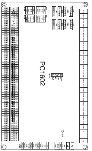
| No. | Sign | Meaning | No. | Sign | Meaning |
| 1 | AI/DI1 | Water inlet temperature | 55 | AI 55(50K) | No use |
| 2 | AI/DI2 | Water outlet temperature | 56 | 0-5V_IN1 | System 1 low pressure sensor |
| 3 | AI/DI3 | System 1 antifreeze temperature | 57 | AI/0-5V_IN2 | System 2 low pressure sensor |
| 4 | AI/DI4 | System 1 coil temperature 1 | 58 | 0-5V_IN3 | System 1 high pressure sensor |
| 5 | AI/DI5 | System 1 coil temperature 2 | 59 | 0-5V_IN4 | System 2 high pressure sensor |
| 6 | AI/DI6 | System 2 antifreeze temperature | 60 | 0-5V_IN5 | No use |
| 7 | AI/DI7 | Ambient temperature | 61 | 0-5V_IN6 | No use |
| 8 | AI/DI8 | System 1 coil outlet temperature | 62 | 0-5V_IN7 | No use |
| 9 | AI/DI9 | System 1 return air temperature | 63 | 0-5V_IN8 | No use |
| 10 | AI/DI10 | System 2 coil outlet temperature | 64 | PWM_IN1 | Flow meter |
| 11 | AI/DI11 | System 2 return air temperature | 65 | PWM_IN2 | No use |
| 12 | AI/DI12 | System 1 EVI inlet temperature | 66 | PWM_OUT1 | No use |
| 13 | AI/DI13 | System 1 EVI outlet temperature | 67 | PWM_OUT2 | No use |
| 14 | AI/DI14 | System 2 EVI inlet temperature | 68 | 0-10V_OUT1 | No use |
| 15 | AI/DI15 | System 2 EVI outlet temperature | 69 | 0-10V_OUT2 | No use |
| 16 | AI/DI16 | Water tank temperature | 70 | +5V | No use |
| 17 | AI/DI17 | End return water temperature | 71 | +12V | 12V output |
| 18 | AI/DI18 | System 2 coil temperature 1 | 72 | JP13_1 | Wire controlled color display |
| 19 | AI/DI19 | System 2 coil temperature 2 | 73 | JP13_2 | Centrally controlled color display |
| 20 | AI/DI20 | No use | 74 | JP13_3 | (Reserved) |
| 21 | AI/DI21 | No use | 75 | CN1 | System 1 electronic expansion valve (big) |
| 22 | AI/DI22 | No use | 76 | CN2 | System 2 electronic expansion valve (big) |
| 23 | AI/DI23 | No use | 77 | CN3 | System 1 electronic expansion valve (small) |
| 24 | AI/DI24 | No use | 78 | CN4 | System 2 electronic expansion valve (small) |
| 25 | AI/DI25 | No use | 79 | CN5 | System 1 EVI electronic expansion valve |
| 26 | AI/DI26 | No use | 80 | CN6 | System 2 EVI electronic expansion valve |
| 27 | AI/DI27 | No use | 81 | CN7 | No use |
| 28 | AI/DI28 | No use | 82 | CN8 | No use |
| 29 | AI/DI29 | No use | 83 | RO01 | System 1 fan output (low speed) |
| 30 | AI/DI30 | No use | 84 | RO02 | System 1 fan output (high speed) |
| 31 | AI/DI31 | No use | 85 | RO03 | System 2 fan output (low speed) |
| 32 | AI/DI31 | No use | 86 | RO04 | System 2 fan output (high speed) |
| 33 | AI/DI33 | No use | 87 | RO05 | System 1 four-way valve output |
| 34 | AI/DI34 | No use | 88 | RO06 | System 2 four-way valve output |
| 35 | AI/DI35 | No use | 89 | RO07 | System 1 crankshaft heating belt output |
| 36 | AI/DI36 | No use | 90 | RO08 | System 2 crankshaft heating belt output |
| 37 | AI/DI37 | System 1 low pressure switch | 91 | RO09 | System 1 spray valve output (No use) |
| 38 | AI/DI38 | System 2 low pressure switch | 92 | RO10 | System 2 spray valve output (No use) |
| 39 | AI/DI39 | System 1 high pressure switch | 93 | RO11 | Water replenishing valve (reserved) |
| 40 | AI/DI40 | System 2 high pressure switch | 94 | RO12 | Backwater valve (reserved) |
| 41 | AI/DI41 | No use | 95 | RO13 | Water supply pump (reserved) |
| 42 | AI/DI42 | No use | 96 | RO14 | Electric heating |
| 43 | AI/DI43 | Water flow switch | 97 | RO15 | Circulating water pump output |
| 44 | AI/DI44 | Electric heating overload protection switch | 98 | RO16 | Alarm output |
| 45 | AI/DI45 | Emergency switch | 99 | RO17 | System 1 fan output (high speed) |
| 46 | AI/DI46 | Mode switch | 100 | RO18 | System 2 fan output (high speed) |
| 47 | AI/DI47 | Fan 1 overload protection switch | 101 | RO19 | Chassis Heater |
| 48 | AI/DI48 | Fan 2 overload protection switch | 102 | RO20 | No use |
| 49 | AI/DI49 | No use | 103 | RO21A | No use |
| 50 | AI 50(50K) | System 1 exhaust temperature | 104 | RO21B | No use |
| 51 | AI 51(50K) | System 2 exhaust temperature | 105 | RO22A | No use |
| 52 | AI 52(50K) | No use | 106 | RO22B | No use |
| 53 | AI 53(50K) | No use | 107 | RO23 | No use |
| 54 | AI 54(50K) | No use | 108 | RO24 | No use |
Cable Specifications
| Nameplate maximum current | Phase line (Single Phase) | Phase Line (Three Phase) | Earth line | MCB | Creepage Protector | Signal Line |
| No more than 10A | 2 x 1.5mm2 | 3 x 1.5mm2 | 1.5mm2 | 20A |
30mA less than 0.1 sec |
n x 0.5mm2 |
| 10~16A | 2 x 2.5mm2 | 3 x 2.5mm2 | 2.5mm2 | 32A | ||
| 16~25A | 2 x 4mm2 | 3 x 4mm2 | 4mm2 | 40A | ||
| 25~32A | 2 x 6mm2 | 3 x 6mm2 | 6mm2 | 40A | ||
| 32~40A | 2 x 10mm2 | 3 x 10mm2 | 10mm2 | 63A | ||
| 40~63A | 2 x 16mm2 | 3 x 16mm2 | 16mm2 | 80A | ||
| 63~75A | 2 x 25mm2 | 3 x 25mm2 | 25mm2 | 100A | ||
| 75~101A | 2 x 25mm2 | 3 x 25mm2 | 25mm2 | 125A | ||
| 101~123A | 2 x 35mm2 | 3 x 35mm2 | 35mm2 | 160A | ||
| 123~148A | 2 x 50mm2 | 3 x 50mm2 | 50mm2 | 225A | ||
| 148~186A | 2 x 70mm2 | 3 x 70mm2 | 70mm2 | 250A | ||
| 186~224A | 2 x 95mm2 | 3 x 95mm2 | 95mm2 | 280A |
Maintenance
- DO I NEED TO GET MY UNIT SERVICED?
It is recommended that you get your EvoHeat unit serviced once a year by your local certified air conditioning or refrigeration technician. If your unit is located in a coastal area, more frequent maintenance may be necessary. During the service, they will check the operational pressures of the refrigeration system and give the unit and fins a good clean to ensure maximum performance. - DO WE HAVE RECOMMENDED SERVICE AGENTS?
EvoHeat have a large database of recommended service agents. Please contact EvoHeat tech support on 1300 859 933 for your local service agent details. - SHOULD I CHECK MY UNIT REGULARLY?
We recommend you check your unit regularly to avoid potential issues and damage to your heat pump.
Check the water inlet/outlets often for leaks. You should avoid the condition of no water or air entering into the system, as this will influence unit’s performance and reliability.
The area around the unit should be dry, clean and well ventilated. Make sure there is nothing blocking the airflow of the heater e.g. Leaf litter. Clean the heat exchanger every few months to keep a good heat exchange rate and save energy. - WHAT SHOULD I BE CHECKING REGULARLY?
You should discharge the water at the bottom of the water pump if the unit will not be used for an extended period. Discharge all water in the water pump and water system so that freezing of the water in the pump or water system does not occur. Check the unit thoroughly and fill the system with water fully before using it for the first time after a period of time.
Check the power supply and cable connection often, should the unit begin to operate abnormally, switch it off and contact the qualified technician
Clean the water filter periodically to maintain good water quality. Lack of water and dirty water can damage the unit. The heat pump will start the water every 72 hours when it is not running to avoid freezing.
The water loop of the heat pump MUST be protected from freezing in winter. Do not shut off the power supply to the heat pump in winter. When the air temperature is below 0°C, if the inlet water temperature is above 2°C and below 4°C the water pump will begin freezing protection. If the inlet water is lower than 2°C, the heat pump will begin heating.
Warranty
Refer to the EvoHeat website for warranty details
- Australia: https://evoheat.com.au/warranty-terms/
- South East Asia: http://evoheat.com.sg/warranty/
- Warranty terms are from date of purchase.
- This warranty excludes any defect or injury caused by or resulting from misuse, abuse, neglect, accidental damage, improper voltage, vermin infestation, incompetent installation, any fault not attributable to faulty manufacture or parts, any modifications which affect the reliability or performance of the unit.
- This warranty does not cover the following:
- Natural Disasters (hail, lightening, flood, fire etc.)
- Rust or damage to paintwork caused by a corrosive atmosphere
- When serviced by an unauthorized person without the permission of Evo Industries
- When a unit is installed by an unqualified person
- Where a unit is incorrectly installed
- When failure occurs due to improper or faulty installation
- Failure due to improper maintenance (refer Operating Instructions)
- ‘No Fault Found’ service calls where the perceived problem is explained within the
- Costs associated with delivery, handling, freighting, or damage to the product in transit.
- If warranty service is required, you should:
- contact Evo Industries Australia on 1300 859 933 or via our Contact page on our web site
- provide a copy of your receipt as proof of purchase
- have completed the online Warranty Registration Form
- Onsite technical service is available within the normal operating area of your Evo Authorised Service Agents. Service outside this area will incur a traveling fee.
- Unless otherwise specified to the purchaser, the benefits conferred by this express warranty and additional to all other conditions, warranties, rights and remedies expressed or implied by the Trade Practices Act 1974 and similar consumer protection provisions contained in legislation of the States and Territories and all other obligations and liabilities on the part of the manufacturer or supplier and nothing contained herein shall restrict or modify such rights, remedies, obligations or liabilities.
REGISTER YOUR WARRANTY
EvoHeat highly recommend customers complete their warranty details online to ensure efficient warranty claim processing.
To register your warranty, scan our QR Code or head to our website and fill in the Warranty Registration Form: https://evoheat.com.au/warranty-registration/

[email protected]
1300 859 933
www.evoheat.com.au


