EVOHEAT Evo Flex Hot Water and Space Heating Cooling
Introduction
This manual contains all the necessary information in regard to the installation, troubleshooting, operation and maintenance of this unit. Ensure instructions in this manual are adhered to at all times. Failing to comply with these recommendations will invalidate the warranty. This manual and all others are available for download on our website.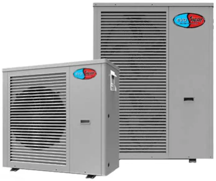
With the application of DC inverter technology, the Evo Flex Series can adjust the output capacity automatically and control the room temperature accurately. The Evo Flex Series is ideal for domestic hot water and space heating and cooling.
- The latest DC invert heat pump technology
- One heat pump for hot water and space heating and cooling
- Energy savings, 30% less energy consumption compared to a fixed-speed heat pump
- Reduces energy use and greenhouse gases
- Precise temperature control
- Speed up heating/cooling time
- Wired controller, easy to operate, the intelligent color touch screen controller
- Intelligent defrosting
- Monobloc design
- Works efficiently with floor heating, water fan coils, or radiators
Unit Specifications
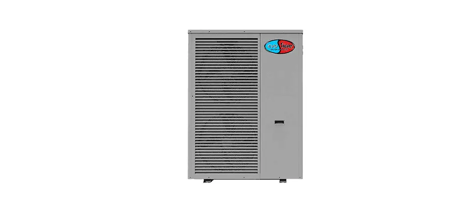
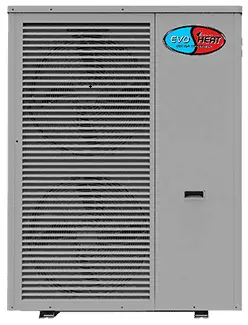
Unit Structure
Evo Flex 10
Evo Flex 17 & 25 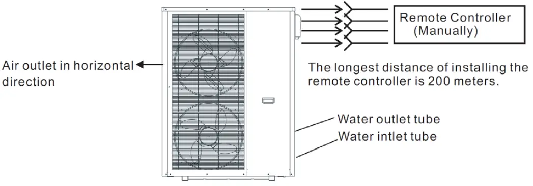
Technical Data
| Evo Flex | 10 | 17 | 25 | |
| Cooling Capacity | kW | 10 | 14.5 | 20 |
| BTU/h | 34121 | 49489 | 68260 | |
| Heating Capacity | kW | 11.5 | 16.5 | 25 |
| BTU/h | 39240 | 56315 | 85325 | |
| Hot Water Capacity | kW | 13.2 | 21.6 | 30 |
| BTU/h | 45040 | 73702 | 102364 | |
| Cooling Power Input | BTU/h | 3.4 | 5.6 | 9.0 |
| Heating Power Input | kW | 3.4 | 5.1 | 9.0 |
| Hot Water Power Input | BTU/h | 3.6 | 6.2 | 8.2 |
| Operation Electric Current (max) | kW | 15.7 | 27 | 14.0 |
| Cooling Capacity Range | kW | 2.0 ~ 10 | 5.0 ~ 14.5 | 7.0 ~ 20.0 |
| Heating Capacity Range | kW | 2.5 ~ 11.5 | 5.0 ~ 16.5 | 8.0 ~ 25.0 |
| Hot Water Capacity Range | A | 4.2 ~ 13.2 | 7.4 ~ 21.6 | 11.0 ~ 30.0 |
| Cooling Power Input Range | kW | 1.0 ~ 3.4 | 1.6 ~ 5.6 | 2.5 ~ 9.0 |
| Heating Power Input Range | kW | 0.8 ~ 3.4 | 1.2 ~ 5.1 | 2.5 ~ 9.0 |
| Hot Water Power Input Range | kW | 1.0 ~ 3.6 | 1.5 ~ 6.2 | 2.1 ~ 8.2 |
| Power Supply | 220-240V~/50Hz | 220-240V~/50Hz | 380V/3N~/50Hz | |
| Compressor Quantity | 1 | 1 | 1 | |
| Compressor Model | Rotary | Rotary | Rotary | |
| Fan Quantity | 1 | 2 | 2 | |
| Fan Power Input | W | 75 | 75 X 2 | 150 X 2 |
| Fan Rotate Speed | RPM | 850 | 850 | 900 |
| Noise | dB(A) | 54 | 58 | 62 |
| Water Pump Input | kW | 0.18 | 0.5 | 0.65 |
| Water Head | m | 12.5 | 21 | 22.5 |
| Water Connection | inch | 1 | 1 1/4 | 1 1/4 |
| Water Flow Volume | m3/h | 1.6 | 2.8 | 4.2 |
| Water Pressure Drop (max) | kpa | 24 | 105 | 71 |
| Unit Net Dimensions (L/W/H) | mm | 953*445*910 | 996*395*1320 | 1175*400*1592 |
| Unit Shipping Dimensions (L/W/H) | mm | 1040*490*920 | 1070*435*1340 | 1225*430*1600 |
| Net Weight | kg | See Nameplate | See Nameplate | See Nameplate |
| Shipping Weight | kg | See Package Label | See Package Label | See Package Label |
- Cooling Working Condition: (DB/WB)35°C/24°C, (outlet/inlet) 7°C/12°C
- Heating Working Condition: (DB/WB) 7°C/6°C, (outlet/inlet) 35°C/30°C
- Hot Water Working Condition: (DB/WB) 20°C/15°C, (outlet/inlet) 40°C/45°C
- BS EN 14511-1-2013 Air Conditioner, whole liquid cooling machine, electric compressor. Part 2: Test condition Part 3: Test Method Part 4: Related requirements.
Dimensions
Evo Flex 10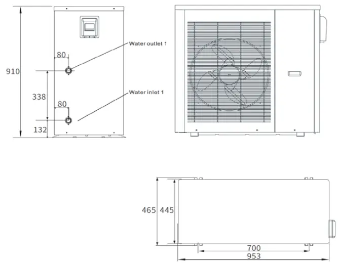
Evo Flex 17 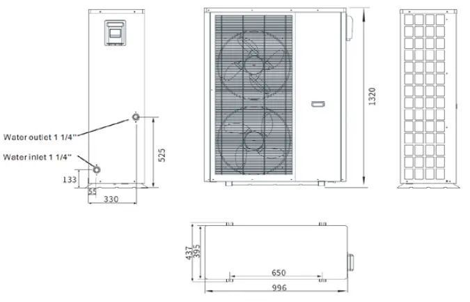
Evo Flex 25 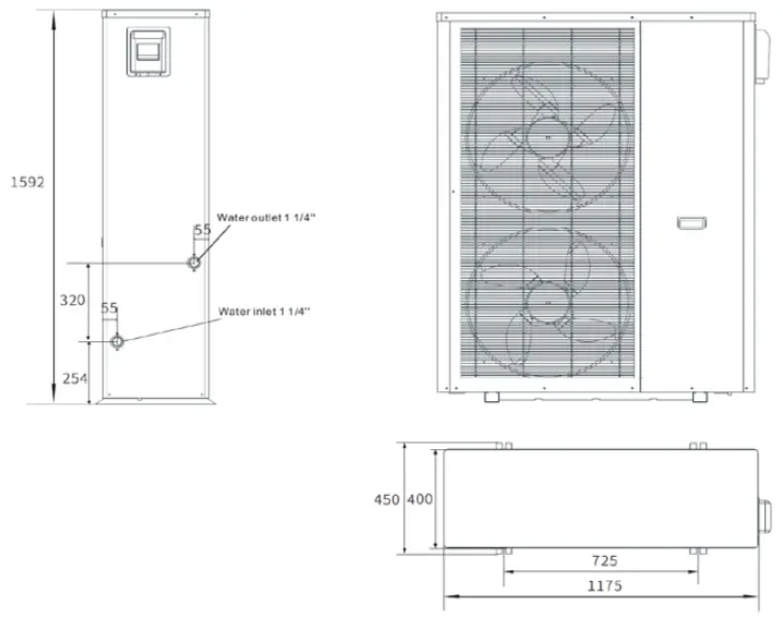
Safety Instructions
- Installation, repair, or relocations must be done by a fully qualified person and not by the customer. If done incorrectly it may cause fire, electric shock, water leakage, and other hazards.
- Maintenance and operation must be carried out according to the recommended time and frequencies, as stated in this manual.
- To avoid the risk of electrical shock, the unit must have a good power connection and earth.
- If the supply cord is damaged, it must be replaced.
- Use genuine standard spare parts only.
- When an abnormality (smell of burning, etc.) occurs, stop the unit and disconnect the power or turn off the breaker. If the unit continues to be operated in an abnormal condition, it may cause a fire or hazards.
- Do not insert fingers or objects into the fans or evaporator of the unit.
- The unit is equipped with an overload protection system. After a previous stoppage, the unit will not start for at least 3 minutes.
- For unit cleaning or maintenance, switch off and disconnect the power of the unit.
- Do not install the unit near flammable gas or spray flammable substances near it.
- Ensure the heat pump is installed on a strong and stable platform.
- A circuit breaker must be installed for the unit.
- Use supply wires suitable for 75°C
Caution: Single wall heat exchanger, is not suitable for potable water connection.
Installation
Based on the local climate conditions, construction features, and insulation level, calculate the required cooling (heating) capacity per square meter. Conclude the total capacity which will be needed by the construction. According to the total capacity needed, choose the right model by consulting the heat pump features as below:
Heat Pump Features
Cooling Only Unit: chilled water outlet temp. at 5-15°C, maximum ambient temp. at 43°C Heating and Cooling Unit: for cooling chilled water outlet temp. at 5-15°C, maximum ambient temp. at 43°C. For heating warm water inlet temp. at 40-50°C, minimum ambient temp. at -10°C.
Unit Application
The Evo Flex can be installed in houses, offices, hotels, and many more locations which require heating and cooling separation, with each area needing to be controlled independently.
Transit
If the unit needs to be hung up during installation, an 8-meter cable is required. There must be a soft material between the cable and the unit to prevent damage to the heat pump cabinet.
WARNING
DO NOT touch the heat exchanger of the heat pump with fingers or other objects!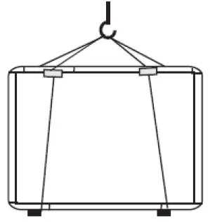
Application of Heat Pump for Cooling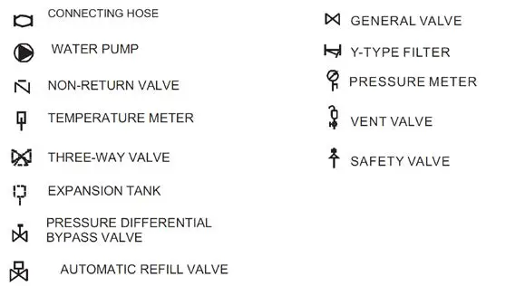
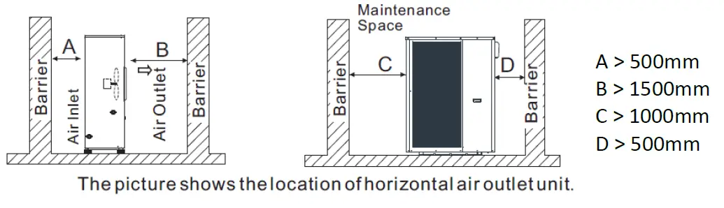
Location of Install & Minimum Clearances
The heat pump can be installed onto the concrete basement by using expansion screws, or onto a steel frame with rubber feet that can be placed on the ground or the roof. Ensure that the unit is placed horizontally.
- The unit can be installed in any place outdoors which will be able to support the weight of a heavy unit such as a terrace, roof, the ground and any other places deemed suitable.
- The location must have good ventilation.
- The location must be free from heat radiation and other fire hazards.
- A pall is needed in winter to protect the unit from snow.
- There must be no obstacles near the inlet and outlet of the unit.
- The installation location must be protected from strong winds or air.
- There must be a water channel around the heat pump to drain condensing water.
- Leave enough space around the unit for maintenance.

Water Loop Connection
Pay attention to the below matters when the water pipe is connected.
- Try to reduce the resistance to the water from the piping.
- The piping must be clear and free from dirt and blockage. A water leakage test must be carried out to ensure that there is no water leaking before the installation can be made.
- The pipe must be tested by pressure separately. DO NOT test it together with the unit.
- There must be an expansion tank on the top point of the water loop, and the water level inside the tank must be at least 0.5meters higher than the top point of the water loop.
- The flow switch is installed inside of the heat pump, check to ensure that the wiring and action of the switch is normal and controlled by the controller.
- Try to avoid any air from being trapped inside the water pipe, there must be an air vent on the top point of the water loop.
- There must be a thermometer and pressure meter at the water inlet and outlet for easy inspection during running.
Electrical Connection
- Open the front panel and open the power supply access.
- The power supply must go through the wire access and be connected to the power supply terminals in the controlling box. Then connect the 3-signal wire plugs of the wired controller and main controller.
- If an external water pump is required, please insert the power supply wire into the wire access and connect it to the water pump terminals.
- If an additional auxiliary heater is needed to be controlled by the heat pump controller, the relay (or power) of the aux-heater must be connected to the relevant output of the controller.
Initial Start-up of the Unit
INSPECTION BEFORE TRIAL RUNNING
- Check the indoor unit, and make sure that the pipe connection is done correctly, and the relevant valves are open.
- Check the water loop to ensure that the water inside of the expansion tank is filled to an appropriate level, the water supply is working, and the water loop is full of water and free of trapped air. Make sure there is good insulation for the water pipe.
- Check the electrical wiring. Make sure that the power voltage is normal, the screws are fastened, the wiring is made in line with the diagram, and that the earthing is connected.
- Check that the heat pump includes all the screws and components and that they are in good order. When powering the unit on, review the indicator on the controller to see if there is any indication of failure. The gas gauge can be connected to the check valve to see the high pressure (or low pressure) of the system during the trial run.
TRIAL RUNNING
- Start the heat pump by pressing the ‘POWER’ button key on the controller. Check whether the water pump is running, if it runs normally there will be 0.2MPa on the water pressure meter.
- When the water pump has run for a minute, the compressor will start. Listen for any strange sounds from the compressor, if an abnormal sound occurs please stop the unit and check the compressor. If the compressor runs well please look for the pressure meter of the refrigerant.
- Check whether the power input and running current is in line with the manual. If not please stop and check.
- Adjust the valved on the water loop to make sure that the hot (cool) water supply to each door is good and meets the requirements of heating (or cooling).
- Review whether the outlet water temperature is stable.
- The parameters of the controller are set by the factory, the user cannot change these themselves.
Operation
Main Interface Display and Function 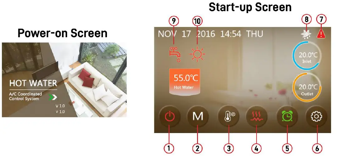
| Key No. | Key Name | Key Function |
| 1 | On and off | Click this key to switch ON or OFF Red represents ON, while grey represents OFF |
| 2 | Mode key | Hot water mode, heating mode, cooling mode, hot water + heating mode or hot water + cooling mode can be selected by pressing this key |
| 3 | Temperature setting | Click this to set the target temperature |
| 4 | Fast heating | Click this key to start rapid heating This key will be displayed during heating |
| 5 | Timer setting | Click this key to set the timer. White represents not enabled, while green represents enabled |
| 6 | Setup key | Click this key to check the unit status, time, factory parameters, temperature curve, timer setting and mute setting |
| 7 | Fault icon | This icon will flash when there is an error occurring, then the display will enter the failure record interface after tapping this icon |
| Icon No. | Icon Name | Meaning |
| 8 | Defrosting | The machine is in defrosting mode when this icon is shown |
| 9 | Hot Water Mode | This machine is in hot water mode then this icon is shown |
| 10 | Heating Mode | This machine is in heating mode when this icon is displayed |
Functions of the Controller
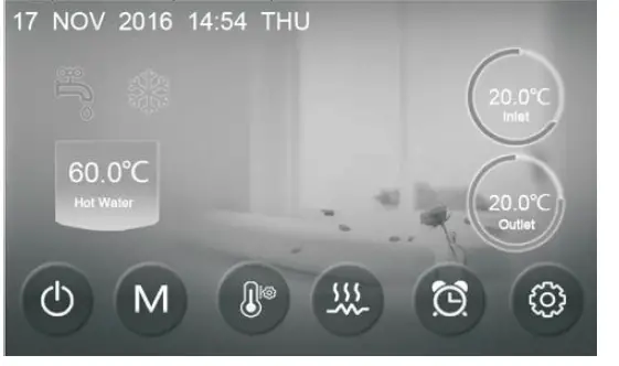
Turning On & Off
- In the shut-down interface (on/off key will be in grey), press the on/off key to start the unit
- In the starting-up interface (on/off key will be red), pressing on/off will turn the unit off

Mode Switch
In the main interface, there are five modes that can be selected after tapping the mode key: Note: If you have purchased a heating-only model (with no cooling functions), the “cooling” mode will not appear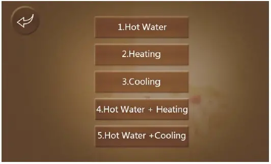
Setting Target Temperature 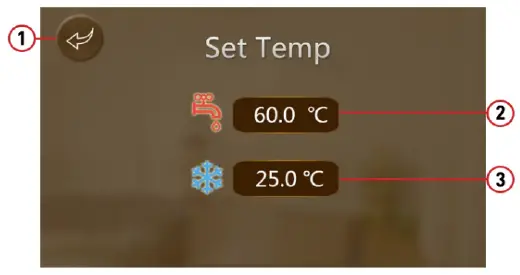
- Pressing (1) will bring the controller back to the main interface
- Pressing (2) will allow the target temperature to be set, a pop-up keyboard will appear
- Pressing (3) will allow the target temperature of cooling mode to be set through the keyboard
When the target temperature is being set, the following keyboard will appear 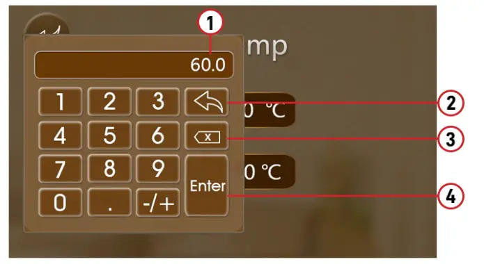
- New target temperature under current settings
- Return Key: returns you to the main interface
- Delete Key: will undo your last action
- Enter Key: Saves changes and returns to the menu.
Fast Heating 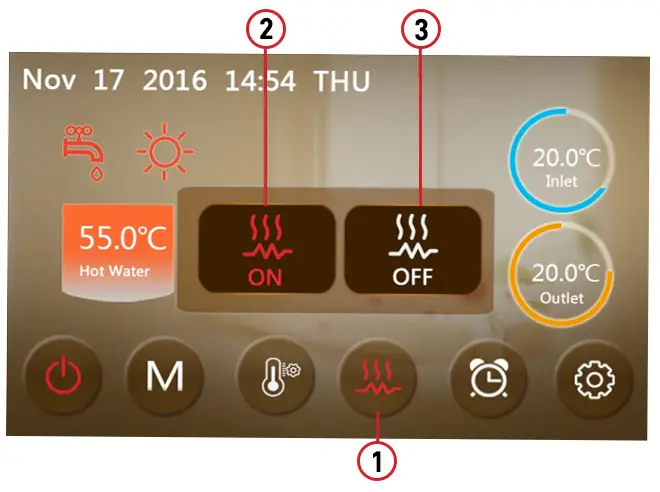
Under heating mode, click the fast heating key (1) and the following interface will appear. Click (2) to start fast-heating mode and (3) to close it.
Timer Setting
Click the timer setting key to enter the timer settings and the following interface will appear
EXAMPLE: The unit will start up at 17:10 and shut down at 20:10.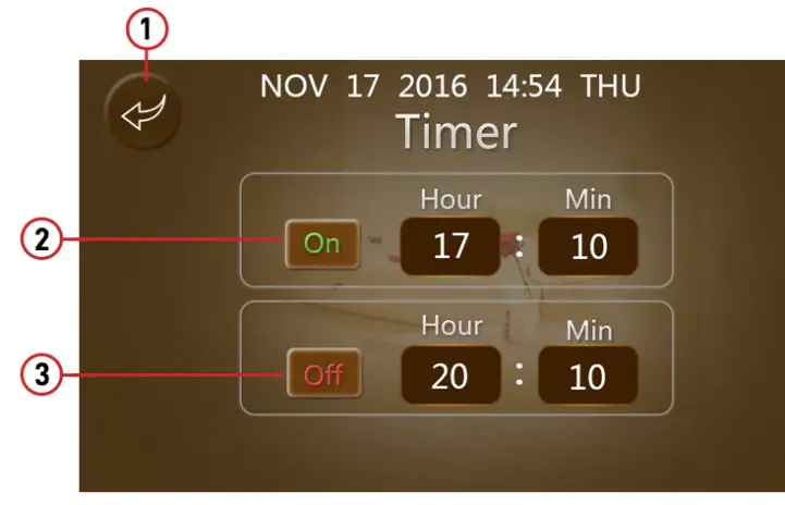
| KEY NAME | KEY COLOUR | KEY FUNCTION | |
| 1 | Return Key | Click this key to return to the main interface | |
| 2 | Enable Timer ON | Enable: Green ON Disable: Grey OFF | Click this key to start or turn off the timed start-up function |
| 3 | Enable Timer OFF | Enable: Green ON Disable: Grey OFF | Click this key to start or turn off the timed start-up function |
Setup Interface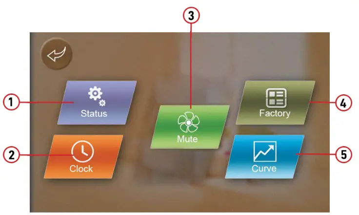
| Key Name | Key Function | |
| 1 | Status Key | Click this key to get into the status interface |
| 2 | Clock Key | Click this key to set the operational time function |
| 3 | Mute Key | Click to turn on/off silent function and to set the timing interval function |
| 4 | Factory Key | Click this key to get into the factory interface |
| 5 | Curve Key | Click this key to look up the temperature curve |
Setting the Date & Time
From the setup interface, press Clock to enter into the date & time setting interface. Use the arrows to adjust the date and time as required, then press the Enter button to save changes. Press the return key to return to the previous interface or press cancel to exit current settings.
Note: in Fahrenheit mode, the system date format is: dd/mm/yy.
Fault Interface
Click the fault icon on the main interface and it will display as follows: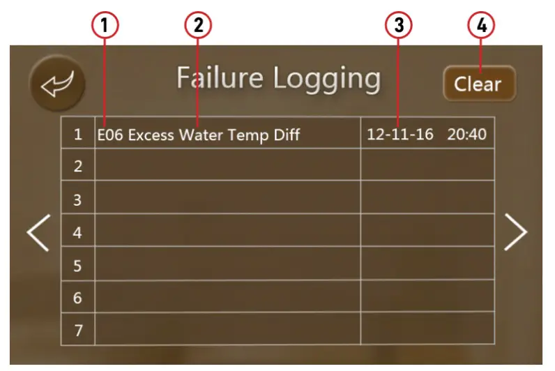
| 1 | Fault code |
| 2 | Fault Name |
| 3 | Date of fault occurrence (dd/mm/yy) |
| 4 | Click to clear all fault records |
NOTE: When clearing the fault records, it will ask for a code. The password will be according to the display date.
For example, if the display date is 12/11/2016, then the password is 12.
Colour Display Calibration
Keep clicking quickly at the blank area on any interface till you hear a long beep. Then you will enter the calibration interface. Click “+” to start calibration. When you hear the beep again, you will have finished calibration and can exit.
Troubleshooting
Electronic Control Fault Table
| Protect/Fault | Fault Display | Reason | Elimination Methods |
| Inlet Temp. Sensor Fault | P01 | The temp. the sensor is broken or short-circuited | Check or change the temp. sensor |
| Outlet Temp. Sensor Fault | P02 | The temp. the sensor is broken or short-circuited | Check or change the temp. sensor |
| Water Tank Temp Sensor | P03 | The temp. the sensor is broken or short-circuited | Check or change the temp. sensor |
| At Sensor Fault | P04 | The temp. the sensor is broken or short-circuited | Check or change the temp. sensor |
| Suction Temp. Sensor Fault | P17 | The temp. the sensor is broken or short-circuited | Check or change the temp. sensor |
| Coil Temp Sensor | P153 | The temp. the sensor is broken or short-circuited | Check or change the temp. sensor |
| Exhaust Temp Sensor | P181 | The temp. the sensor is broken or short-circuited | Check or change the temp. sensor |
| Exhaust Overtemp | P182 | The temp. the sensor is broken or short-circuited | Check or change the temp. sensor |
| Suction Pressure Sensor Fault | PP2 | The pressure sensor is broken | Check or change the pressure sensor or pressure |
| Exhaust Pressure Sensor Fault | PP1 | The pressure sensor is broken | Check or change the pressure sensor or pressure |
| Low AT Protection | TP | The environment temp. is low | |
| Electric Overheat Protection | E04 | The compressor is overloaded | Check whether the system of the the compressor is running normally |
| Communication Fault | E08 | Communication failure between wire controller and mainboard | Check the wire connection between remote wire controller and main board |
| HP Protection | E11 | The high-pressure switch is broken | Check the pressure switch and cold circuit |
| LP Protection | E12 | Low pressure1 protection | Check the pressure switch and cold circuit |
| Primary Anti-Freezing Prot. | E19 | The ambient temp. is low | |
| Secondary Anti-Freezing Prot. | E29 | The ambient temp. is low | |
| Flow Switch Protection | E032 | No water/little water in water system | Check the pipe water flow and water pump |
| Compressor Overcurrent Shutdown Fault | E051 | The compressor is overloaded | Check whether the system of the the compressor is running normally |
| Anti-Freezing Prot | E171 | Water flow is not enough | Check the pipe water flow and whether the water system is jammed or not |
| DC Fan Motor 1 Failure | F031 | 1. Motor is in locked-rotor state 2. The wire connection between the DC-fan motor module and fan motor is in bad contact | 1. Change a new fan motor 2. Check the wire connection and make sure they are in good contact |
| DC Fan Motor 2 Failure | F032 | 1. Motor is in locked-rotor state 2. The wire connection between the DC-fan motor module and fan motor is in bad contact | 1. Change a new fan motor 2. Check the wire connection and make sure they are in good contact |
| Dc Fan Motor Comms Failure | E081 | The speed control module and main board communication fail | Check the communication connection |
Frequency Conversion Board Fault Table
| Protection/Fault | Fault Display | Reason | Elimination Methods |
| IPM Overcurrent Shutdown Fault | F00 | IPM Input current is large | Check and adjust the current measurement |
| Compressor Activation Failure | F01 | Lack of phase, step or drive hardware damage | Check the measuring voltage, check the frequency conversion board hardware |
| PFC Fault | F03 | The PFC circuit protection | Check the PFC switch tube short circuit or not |
| DC Bus Overload | F05 | DC bus voltage<Dc bus Overload – voltage protection value | Check the input voltage measurement |
| DC Bus Underload | F06 | DC bus voltage<Dc bus underload – voltage protection value | Check the input voltage measurement |
| AC Input Underload | F07 | The input voltage is under, causing the input current to be too low | Check the input voltage measurement |
| AC Input Overload | F08 | The input voltage is over, causing the input current to be too high | Check and adjust the current measurement |
| Input Voltage Sample Fault | F09 | The input voltage sampling fault | Check and adjust the current measurement |
| Communication Failure between DSP and PFC | F10 | DSP and PFC connect fault | Check the communication connection |
| Communication Fault (DSP) | F11 | DSP and Inverter board communication failure | Check the communication connection |
| Communication Fault (Inverter Board) | F12 | Communication failure between inverter board and main board | Check the wire connection between remote inverter board and main board |
| IPM Overheat Stop | F13 | The IPM module has overheated | Check and adjust the current measurement |
| Weak Magnetism Alarm | F14 | Compressor magnetic force is not enough | |
| Input Voltage Lacking Phase | F15 | The input voltage lost phase | Check and measure the voltage adjustment |
| IPM Current Sample Fault | F16 | IPM Sampling electricity is fault | Check and adjust the current measurement |
| Sensor Fault of Module/Radiator | F17 | The transducer is overheating | Check and adjust the current measurement |
| IGBT Power Device Overhear Alarm | F20 | The transducer is overheating | Check and adjust the current measurement |
| Overload Alarm | F21 | The compressor input current is too large | Check and adjust the current measurement |
| AC Input OverCurrent Alarm | F22 | Input current is too large | Check and adjust the current measurement |
| EEPROM Fault Alarm | F23 | MCU Error | |
| Destroyed EEPROM Activation Ban Alarm | F24 | MCU Error | |
| LP 15V Underload Fault | F25 | The V15V is overload or undervoltage | Check the V15V input voltage in range 13.5V~16.5 or not |
| IGBT Power Device Overheat Fault | F26 | The transducer temperature is too high | Check and adjust the current measurement |
Troubleshooting Table
| Failure | Possible Causes for the Failure | Solutions |
| Heat pump cannot be started | Wrong power supply | Shut off the power and check power supply |
| Power supply cable loose | Check power cable and make right connection | |
| Circuit breaker open | Check for the cause and replace the fuse or circuit breaker | |
| Water pump is running with high noise or without a heater | Lack of water in the piping | Check the water supply and charge water to the piping |
| Too much air in the water loop | Discharge the air in the water loop | |
| Water valves closed | Open the valves in the water loop | |
| Dirt and blockage on the water filter | Clean the water filter | |
| The heat pump capacity is low, the compressor does not stop | Lack of refrigerant | Check for gas leakage and recharge the refrigerant |
| Bad insulation on the water pipe | Make good insulation on the water pipe | |
| Low heat exchange rate on airside exchanger | Clean the air side heat exchanger | |
| Lack of water flow | Clean the water filter | |
| High compressor exhaust | Too much refrigerant | Discharge the redundant gas |
| Low heat exchange rate on air side exchanger | Clean the air side heat exchanger | |
| The low-pressure problem of the system | Lack of gas | Check the gas leakage and recharge freon |
| Block on filter or capillary | Replace filter or capillary | |
| Lack of water flow | Clean the water filter and discharge the air into the water loop | |
| Compressors do not run | Power supply failure | Check off the power supply |
| Compressor contactor broken | Replace compressor contractor | |
| Power cable lose | Tighten the power cable | |
| Protection on compressor | Check the compressor exhaust temp | |
| Wrong setting on return water temp | Reset the return water temp | |
| Lack of water flow | Clean the water filter and discharge the air in the water loop | |
| High noise of the compressor | Liquid refrigerant goes into the compressor | Bad evaporation, check the cause for bad evaporation and fix |
| Compressor failure | Use new compressor | |
| Fans do not run | Failure on fan relay | Replace the fan relay |
| Fan motor broken | Replace fan motor | |
| The compressor runs but the heat pump has no heating or cooling capacity | No gas in the heat pump | Check system leakage and recharge refrigerant |
| Heat exchanger broken | Find out the cause and replace the heat exchanger | |
| Compressor failure | Replace compressor | |
| Low outlet water temperature | Low water flow rate | Clean the water filter and discharge the air in water loop |
| Low setting for the desired water temp | Reset the desired water temperature | |
| Low water flow protection | Lack of water in the system | Clean the water filter and discharge the air in the water loop |
| Failure of the flow switch | Replace the flow switch |
Appendix
Parameter List
| Meaning | Default | Remarks |
| Refrigeration target temperature set point | 12°C | Adjustable |
| Heating the target temperature set point | 40°C | Adjustable |
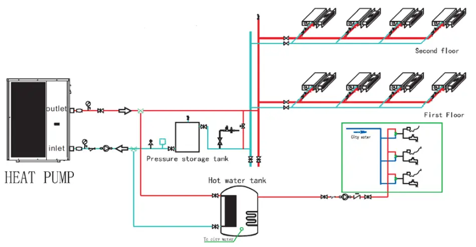
Install Sketch Map
Special installation (expandable water tank)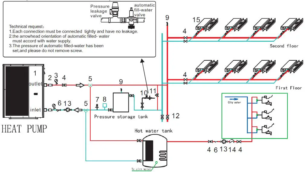
- Main Unit
- Connecting Hose
- Pressure Meter
- General Valve
- Three-way Valve
- Y-type Filter
- Safety Valve
- Expansion Tank
- Vent Valve
- Automatic Refill Valve
- Pressure Differential Bypass Valve
- Drain Valve
- Non-return valve
- Water Pump
- Fan Coil
Installation Request:
- The Factory only offers one main unit (1) in the legend, and the other modules which are indispensable fittings are provided by users or the installation company.
- An automatic refill valve (10) is installed on the top point of the water system.
- The quantity proportion of general valve (4) and three-way valve (5) is referred to the technical regulation, and there is a three-way valve installed in the farthest place of water systems.
Automatic Filled-Water
When the automatic filled-water valve is installed, the arrowhead orientation of inlet water must accord with the orientation of the valve.
Automatic filled water has been adjusted in advance to 1.5ba.
If readjusting the pressure of inlet water, please operate as follows:
- Open the Screw Cap ( C ).
- If reducing the pressure of the water supply, unscrew the pressure to adjust the screw (B).
- If increasing the pressure of the water supply, screw down the pressure to adjust the screw (B).

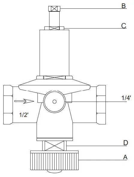
When the system needs to be filled with water at first, rest the handle (A) of the filled water. Then the handle (A) can return (close) when the system is full of water.
The automatic filled-water valve needs periodic cleaning. When you must close the tap, unscrew the plug (D), and remove the inside filter net. Reassemble after cleaning.
NOTE:
There are two connections for water pressure meters in the central section of automatic filled-water, where the water pressure meter can be connected directly and display the set pressure. The screw cap ( C ) must be tweaked after adjusting the filled-water pressure.
Leakage Pressure Valve
The action pressure of the leakage pressure valve is more than 3bar (valve is open), but the pressure cannot be adjusted. The valve will open automatically to make sure that the water loop of the air-con system is safe when the water pressure in the backwater side is higher than the set pressure.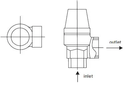
Assistant Heat Source Connection
The unit provides the connection of an assistant heat source which can not be only for a gas-fired boiler, but also for an electronic boiler or warm-net pipe for the city accordingly.
Water Chiller and Heat Pump + Assistant Gas-Fired Boiler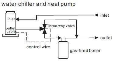
Water Chiller and Heat Pump + Assistant Electronic Boiler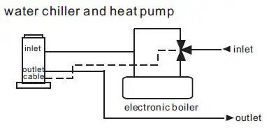
Cable Specifications
Single Phase Unit
| Nameplate max. current | Phase Line | Earth Line | MCB | Creepage Protector | Signal Line |
| No More than 10A | 2 x 1.5mm2 | 1.5mm2 | 20A |
30mA less than 0.1 sec |
n x 0.5mm2 |
| 10~16A | 2 x 2.5mm2 | 2.5mm2 | 32A | ||
| 16~25A | 2 x 4mm2 | 4mm2 | 40A | ||
| 25~32A | 2 x 6mm2 | 6mm2 | 40A | ||
| 32~40A | 2 x 10mm2 | 10mm2 | 63A | ||
| 40~63A | 2 x 16mm2 | 16mm2 | 80A | ||
| 63~75A | 2 x 25mm2 | 25mm2 | 100A | ||
| 75~101A | 2 x 25mm2 | 25mm2 | 125A | ||
| 101~123A | 2 x 35mm2 | 35mm2 | 160A | ||
| 123~148A | 2 x 50mm2 | 50mm2 | 225A | ||
| 148~186A | 2 x 70mm2 | 70mm2 | 250A | ||
| 186~224A | 2 x 95mm2 | 95mm2 | 280A |
Three Phase Unit
| Nameplate max. current | Phase Line | Earth Line | MCB | Creepage Protector | Signal Line |
| No More than 10A | 3 x 1.5mm2 | 1.5mm2 | 20A |
30mA less than 0.1 sec |
n x 0.5mm2 |
| 10~16A | 3 x 2.5mm2 | 2.5mm2 | 32A | ||
| 16~25A | 3 x 4mm2 | 4mm2 | 40A | ||
| 25~32A | 3 x 6mm2 | 6mm2 | 40A | ||
| 32~40A | 3 x 10mm2 | 10mm2 | 63A | ||
| 40~63A | 3 x 16mm2 | 16mm2 | 80A | ||
| 63~75A | 3 x 25mm2 | 25mm2 | 100A | ||
| 75~101A | 3 x 25mm2 | 25mm2 | 125A | ||
| 101~123A | 3 x 35mm2 | 35mm2 | 160A | ||
| 123~148A | 3 x 50mm2 | 50mm2 | 225A | ||
| 148~186A | 3 x 70mm2 | 70mm2 | 250A | ||
| 186~224A | 3 x 95mm2 | 95mm2 | 280A |
If the unit is to be installed outdoors, use a UV-resistant cable.
Controller Interface Drawing
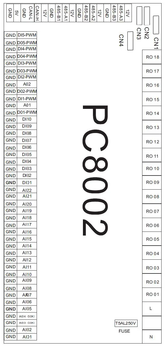
| No. | Sign | Meaning |
| 01 | RO 01 | Compressor (output 220-230VAC) |
| 02 | RO 02 | Water Pump (output 220-230VAC) |
| 03 | RO 03 | 4-way valve (output 220-230VAC) |
| 04 | RO 04 | Fan (output 220-230VAC) |
| 05 | RO 05 | Reserved |
| 06 | RO 06 | Anti-freezing heater (output 220-230VAC) |
| 07 | RO 07 | Crankshaft Heater (output 220-230VAC) |
| 08 | RO 08 | Spray Valve (output 220-230VAC) |
| 09 | RO 09 | Electric Auxiliary Heater (output 220-230VAC) |
| 10 | RO 10 | Reserved |
| 12 | RO 11 | Alarm (output 220-230VAC) |
| 12 | RO 12 | Hot Water Pump |
| 13 | RO 13 | Electromagnetic three-way valve |
| 14 | RO 14~RO18 | Reserved |
| 15 | AC-L | Live Wire (output 220-230VAC) |
| 16 | AC-N | Neutral Wire (output 220-230VAC) |
| 17 | AI01 | Water Inlet Temperature (input) |
| 18 | AI02 | Water output temperature (input) |
| 19 | AI03 | System exhaust temperature (input) |
| 20 | AI04 | Reserved |
| 21 | AI05 | System suction temperature (input) |
| 22 | AI06 | System coil temperature (input) |
| 23 | AI07 | Ambient temperature (input) |
| 24 | AI08 | Water tank temperature (input) |
| 25 | AI09-AI20 | Reserved |
| 26 | AI21 | Suction pressure input |
| 27 | AI22 | Exhaust pressure input |
| 28 | DI01 | System high pressure (input) |
| 29 | DI02 | System low pressure (input) |
| 30 | DI03 | Water flow switch (input) |
| 31 | DI04 | Emergency switch (input) |
| 32 | DI05 | Mode switch (input) |
| 33 | DI06 | Master-slave machine switch (input) |
| 34 | DI07 | Electric heating overload protection switch (input) |
| 35 | 485_A1 | Frequency Conversion Board Communications |
| 36 | 485_B1 | Frequency Conversion Board Communications |
| 37 | 485_A2 | Communicate with wire controller and DC fan module |
| 38 | 485_B2 | Communicate with wire controller and DC fan module |
| 39 | 485_A3 | Reserved |
| 40 | 485_B3 | Reserved |
| 41 | 12V | 12V (output) |
| 42 | 5V | 5V (output) |
| 43 | CN1 | Electronic expansion valve |
| 44 | CN2-CN4 | Reserved |
Maintenance
Do I need to get my unit serviced?
It is recommended that you get your EvoHeat unit serviced once a year by your local certified air conditioning or refrigeration technician. If your unit is located in a coastal area, more frequent maintenance may be necessary. During the service, they will check the operational pressures of the refrigeration system and give the unit and fins a good clean to ensure maximum performance.
Do we have recommended service agents?
EvoHeat has a large database of recommended service agents. Please contact EvoHeat tech support on 1300 859 933 for your local service agent details.
Should I check my unit regularly?
We recommend you check your unit regularly to avoid potential issues and damage to your heat pump.
What should I be checking regularly?
Check the water inlet/outlets often for leaks. You should avoid the condition of no water or air entering the system, as this will influence the unit’s performance and reliability.
The area around the unit should be dry, clean, and well-ventilated. Make sure there is nothing blocking the airflow of the heater e.g. Leaf litter. Check the power supply and cable connection often, should the unit begin to operate abnormally, switch it off and contact the qualified technician.
Warranty
Please refer to the EvoHeat website for warranty details
- Australia: www.evoheat.com.au.
- South East Asia: www.evoheat.com.sg.

- Warranty terms are from the date of purchase.
- This warranty excludes any defect or injury caused by or resulting from misuse, abuse, neglect, accidental damage, improper voltage, vermin infestation, incompetent installation, any fault not attributable to faulty manufacture or parts, or any modifications which affect the reliability or performance of the unit.
- This warranty does not cover the following:
- Natural Disasters (hail, lightning, flood, fire, etc.)
- Rust or damage to paintwork caused by a corrosive atmosphere
- When serviced by an unauthorized person without the permission of Evo Industries
- When a unit is installed by an unqualified person
- Where a unit is incorrectly installed
- When failure occurs due to improper or faulty installation
- Failure due to improper maintenance (refer to Operating Instructions)
- ‘No Fault Found’ service calls where the perceived problem is explained within the
- Costs associated with delivery, handling, freighting, or damage to the product in transit.
- If warranty service is required you should:
- contact Evo Industries Australia on 1300 859 933 or via our Contact page on our website
- provide a copy of your receipt as proof of purchase
- have completed the online warranty registration or provide a completed warranty card.
- Onsite technical service is available within the normal operating area of your Evo Industries authorized Service Centre. Service outside this area will incur a traveling fee.
- Unless otherwise specified to the purchaser, the benefits conferred by this express warranty and additional to all other conditions, warranties, rights, and remedies expressed or implied by the Trade Practices Act 1974 and similar consumer protection provisions contained in the legislation of the States and Territories and all other obligations and liabilities on the part of the manufacturer or supplier and nothing contained herein shall restrict or modify such rights, remedies, obligations or liabilities.
Warranty Registration
EvoHeat highly recommends customers complete their warranty details online to ensure efficient warranty claim processing. To register your warranty, scan our QR Code or head to our website and fill in the Warranty Registration Form: https://evoheat.com.au/warranty-registration/.
evoheat.com.au. 1300 859 933 [email protected].


