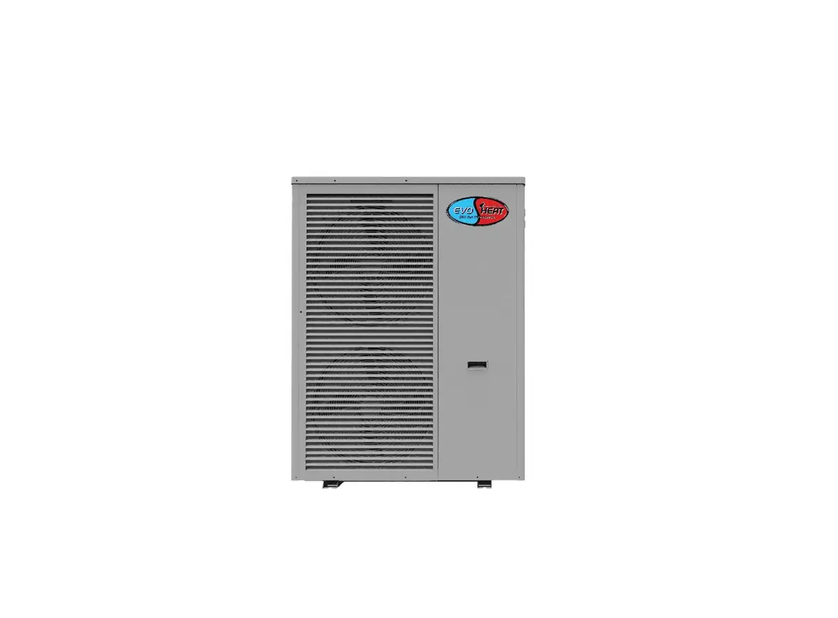
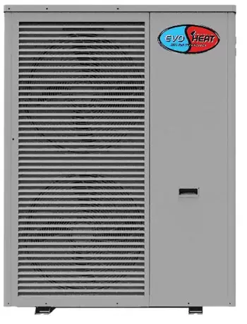
EVO HEAT EVO FLEX Domestic Hot Water and Space Heat Pump
Introduction
This manual contains information relating to the installation, troubleshooting, operation, and maintenance of this EvoHeat unit. Instructions in this manual must always be followed. Failure to comply with these recommendations will invalidate the warranty. Should you have any questions or require technical support, call the EvoHeat office on 1300 859 933 to speak to our team.
The data and information contained in this manual is correct at the time of publishing and is subject to change without notice. For the most up to date manual, contact EvoHeat directly.
The Evo Flex Series heat pumps utilise advanced heat pump technology to achieve high efficiency with a C.O.P. of up to 4.8. With the application of DC inverter technology, the Evo Flex Series can adjust the output capacity automatically and control the room temperature accurately.
| TECHNICAL DATA | Evo Flex 10 | Evo Flex 17 | Evo Flex 25 | |
| Heating Capacity Range | kW | 2.5-10.8 | 5.0-17.3 | 7.0-25.1 |
| Heating Power Input Range | kW | 0.8-2.77 | 1.2-4.55 | 2.5-6.54 |
| Cooling Capacity Range | kW | 2.0-10.0 | 5.0-14.5 | 7.0-20.0 |
| Cooling Power Input Range | kW | 1.0~3.4 | 1.6~5.6 | 2.5~9.0 |
| Frequency | Hz | 30~90 | 30~90 | 30~90 |
| ErP Level (35˚C) | / | A++ | A++ | A++ |
| ErP Level (55˚C) | / | A+ | A+ | A+ |
| Power Supply | / | 220-240/1/50 | 220-240/1/50 | 380-415/3/50 |
| Electric Heater | kW | 3.0 | / | / |
| Max. Running Current | A | 18+13.7 | 27 | 14 |
| Refrigerant Type | / | R410A | R410A | R410A |
| Refrigerant Quantity | kg | 2.4 | 3.2 | 4.4 |
| Water Connection | / | 1” | 1 ¼” | 1 ¼” |
| Water Flow | m3h | 1.6 | 2.8 | 4.2 |
| Water Pressure Drop | kPa | 22 | 52 | 45 |
| Water Pump Head | M | 10 | 17 | 18 |
| DC Fan Motor Quantity | / | 1 | 2 | 2 |
| DC Motor Power Input (MIN-MAX) | W | 18-136 | 36-272 | 50-340 |
| DC Fan Speed (MIN-MAX) | rpm | 300-850 | 300-850 | 300-900 |
| Pressure Sensor 1 | Bar | 0~20 | 0~20 | 0~20 |
| Pressure Sensor 2 | Bar | 0~45 | 0~45 | 0~45 |
| Noise | dB(A) | 54 | 58 | 62 |
| Net Weight | kg | 110 | 163 | 219 |
| Net Dimensions (LxWxH) | mm | 980 x 465 x 910 | 990 x 437 x 1315 | 1175 x 450 x 1588 |
| Operation Ambient Temp. | ˚C | -20~52 | -20~52 | -20~52 |
Dimensions
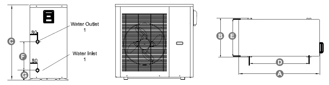
| Evo Flex | A (L) | B (W) | C (H) | D | E | F | G |
| 10 | 980 | 465 | 910 | 700 | 445 | 338 | 132 |
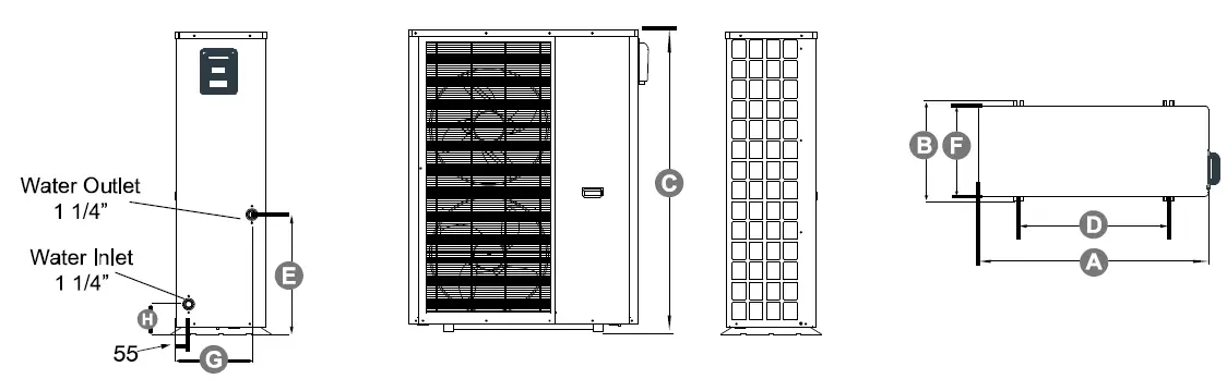
| Evo Flex | A (L) | B (W) | C (H) | D | E | F | G | H |
| 17 | 990 | 437 | 1315 | 650 | 525 | 395 | 330 | 133 |
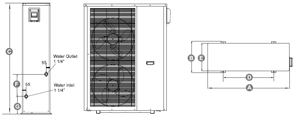
| Evo Flex | A (L) | B (W) | C (H) | D | E | F | G |
| 25 | 1175 | 450 | 1588 | 725 | 400 | 320 | 254 |
Safety Instructions
- Installation, repairs and maintenance of this unit must be performed by a qualified technician.
- Any wiring must comply with local electrical regulations.
- If any abnormal instances occur or a strange smells, the unit must be shut off by the power supply.
- Do not put fingers or objects into the fans or evaporator of the unit.
- The unit must be earthed to avoid any risk caused by insulation defects.
- No wiring must come into contact with the heat source or the rotating fan parts.
- The unit must be handled and lifted with appropriate equipment in correlation with the unit’s size and weight.
- Electrical power must be switched off before any work is started on the unit.
- Do not expose the unit to or install near any flammable gases.
- Ensure there is a circuit breaker for this unit.
- Copper and iron can not be used as a fuse.
- The unit is equipped with an over-load protection system. After a previous stoppage, the unit will not start for at least 3 minutes.
- If the supply cord is damaged, it must be replaced by the manufacturer, our service agent or a similarly qualified person in order to avoid a hazard.
- USE SUPPLY WIRES SUITABLE FOR 75℃.
- Caution: Single wall heat exchanger, not suitable for potable water connection.
WARNING
THIS PRODUCT CONTAINS A BUTTON BATTERY
If swallowed, a lithium button battery can cause severe or fatal injuries within 2 hours.
Keep batteries out of reach of children.
If you think batteries may have been swallowed or placed inside any part of the body, seek immediate medical attention.
Installation
Transit
When transporting the unit, ensure the unit is kept standing upright. Laying the unit down may damage internal parts.
If the unit needs to be hung up (such as for lifting with a crane) use an 8 metre cable. Ensure there is some kind of padding between the cable and the unit to prevent damage to the heat pump cabinet.
Location of Install
The unit can be installed in any outdoor area which can carry the weight of heavy machinery, such as a terrace, rooftop, the ground etc.
- The location must have adequate ventilation and be free from strong winds.
- The installation location must be free from heat radiation and fire hazards.
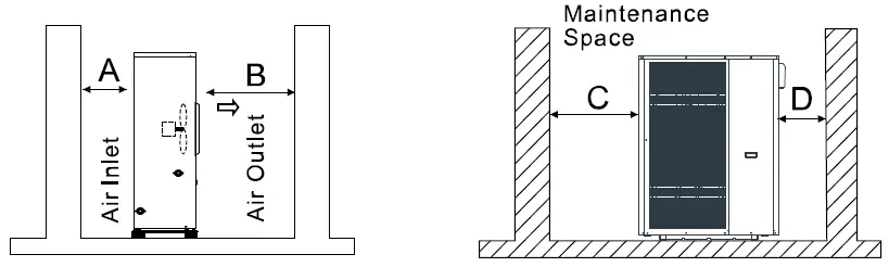
- Ensure there are no obstacles near the air inlet and outlet of the heat pump.
- There must be a water channel around the heat pump to drain condensing water.
- Ensure that there is enough space around the unit for maintenance.
- The heat pump can be installed onto the concrete basement using expansion screws, or onto a steel frame with rubber feet which can be placed on the ground or rooftop. Ensure the unit is placed horizontally.
Minimum Clearances
- A: 500mm
- B: 1500mm
- C: 1000mm
- D: 500mm
Plumbing
- Try to reduce the resistance to the water from the piping.
- The piping must be clear and free from dirt and blockage. A water leakage test must be carried out to ensure that there is no water leaking before the installation can be made.
- The pipe must be tested by pressure separately. DO NOT test it together with the unit.
- There must be an expansion tank on the top point of the water loop, and the water level inside the tank must be at least 0.5meters higher than the top point of the water loop.
- The flow switch is installed inside of the heat pump, check to ensure that the wiring and action of the switch is normal and controlled by the controller.
- Try to avoid any air from being trapped inside the water pipe, there must be an air vent on the top point of the water loop.
- There must be a thermometer and pressure meter at the water inlet and outlet for easy inspection during running.
- There must be drainage on the low points of the water system, and there is already drainage on the chassis of the heat pump. The water in the system must be drained out during winter if the heat pump is not to be used.
Electrical Connection
- Open the panel and open the power line hole
- Thread the power line though the hole and connect it to the power line terminal. The three-core control line of the remote controller shall be plugged with the three-core signal line on the main board according to the wiring diagram.
- For an external water pump, thread the power line of the water pump through the hole and connect it to the water pump terminals.
- If an additional auxiliary heater is needed to be to be controlled by the heat pump controller, the relay (or power) of the aux-heather must be connected to the relevant output of the controller.
Initial Start-up
Prior To:
Check the indoor unit, make sure that the pipe connection is done correctly and that the relevant valves are open.
Check the water loop to ensure that there is enough water inside of the expansion tank, that the water supply is good and that the water loop has no air in it and is full of water. Make sure there in good insulation for the water pipe.
Check the electrical wiring. Make sure that the power voltage is normal, the screws are fastened, the wiring is made in line with the diagram and the earthing is connected.
Check that the heat pump, including all the screws and different parts are in good order. When the power is on, review the indicator on the controller to see if there is any failure indications. The gas gauge can be connected to the check valve to see the high pressure (or low pressure) of the system during trial running.
Trial Operation:
Start the heat pump and check whether the water pump is running, if it is running normally there will be 0.2MPa on the water pressure meter.
When the water pump runs for 1 minute, the compressor will start. Hear whether there is a strange sound coming from the compressor. If an abnormal sound occurs, please stop the unit and check the compressor. If the compressor runs well, look for the pressure meter of the refrigerant.
Check whether the power input and running current is in line with the manual. If not stop the unit and check for why this may be occurring.
Adjust the valves on the water loop to make sure that the hot (cool) water supply to each door is good and meets the requirement of heating (or cooling).
Review whether the outlet water temperature is stable.
Operation
The Controller
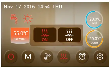
 | ON/OFF | Turn the unit on or off. When the unit is on, the button will be red. |
 | MODE | Switch modes |
 | TEMP. SETTING | Enter the temperature setting menu. |
 | FAST HEATING | Press this to begin rapid heating. |
 | TIMER | Set a unit on/off timer. When a timer is on, this icon will be green. |
 | SETUP | Check the unit status, time, factory parameters, temp. curve, timer & mute settings. |
 |  |  |  |
| FAULT | DEFROSTING | HOT WATER MODE | HEATING MODE |
| When an error occurs this icon will flash at the top right of the screen. Tap the icon to see a record of failures. | When this icon is shown the unit is in defrosting mode. | When this icon is shown the unit is in hot water mode. | When this icon is shown the unit is in heating mode. |
Operating Functions
Start-up & Shutdown
To turn the unit on or off, press ON/OFF ![]() button.
button.
The icon will be grey when the unit is off, and green when it is on.
Mode Switch
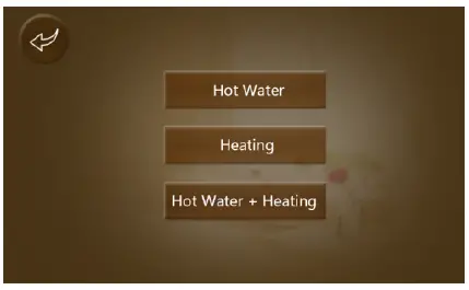
From the main menu there are five different operating modes that can be chosen from. Press MODE ![]() to select from the options:
to select from the options:
Hot Water, Heating, Cooling, Hot Water & Heating or Hot Water & Cooling
Note: If you have purchased a heating-only model (with no cooling functions) “cooling” mode will not appear.
Setting the Target Temperature
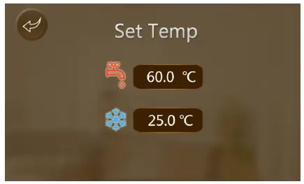
Press the TEMP. SETTING button to change the set temperature values of heating and/or cooling mode.
Press the temperature value to alter the value, then press ‘Enter’ to save and return to the main menu.
Fast Heating Mode
While the unit is in heating mode, press the FAST HEATING ![]() button to enable the rapid heating function.
button to enable the rapid heating function.
Setting a Timer
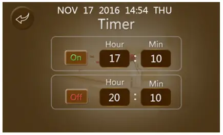
You can set a customised start-up and shutdown timer for your unit.
Press the TIMER ![]() button on the main menu and enter your desired ‘ON’ & ‘OFF’ times.
button on the main menu and enter your desired ‘ON’ & ‘OFF’ times.
Press the On/Off button to the left of each time to toggle the start/end timers. When they are not on the button will be grey instead of coloured.
Example: The unit will turn on at 17:10 and shut down at 20:10.
Setup Interface
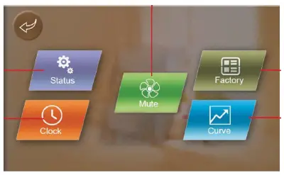
| STATUS | Press this to view the status interface. |
| CLOCK | View/change system time & date settings. |
| MUTE | Turn on/off the silent function OR set mute timing intervals |
| FACTORY | Enter the factory interface. |
| CURVE | View the temperature curves. |
Setting the Date & Time

From the Setup interface, press CLOCK to enter into the system date & time setting menu. Use the arrows to adjust the date & time as required, then press the enter button to save changes.
Press the return key to return to the previous menu or to cancel any changes.
Fault Interface
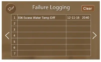
Press the FAULT ![]() icon on the main menu to display a record of all failures that have occurred.
icon on the main menu to display a record of all failures that have occurred.
After faults have been reviewed and corrected, press the top right ‘Clear’ button to wipe the records.
Note: when clearing the fault records, it may ask for a password first. The password will be the first 2 numbers of the top fault. In this example, the password would be 12.
Colour Display Calibration
Keep clicking quickly at the blank area on any interface till you hear a long beep. You will then enter the calibration interface. Click “+” to start calibration. When you hear the beep again, you will have finished calibration and can exit.
Troubleshooting
Electronic Control Fault Table
| Protect/Fault | Error Code | Cause | Solution |
| Inlet Temp. Sensor Fault | P01 | The temp. sensor is broken or short circuited | Check or change the temp. sensor |
| Outlet Temp. Sensor Fault | P02 | The temp. sensor is broken or short circuited | Check or change the temp. sensor |
| Water Tank Temp Sensor | P03 | The temp. sensor is broken or short circuited | Check or change the temp. sensor |
| At Sensor Fault | P04 | The temp. sensor is broken or short circuited | Check or change the temp. sensor |
| Suction Temp. Sensor Fault | P17 | The temp. sensor is broken or short circuited | Check or change the temp. sensor |
| Coil Temp Sensor | P153 | The temp. sensor is broken or short circuited | Check or change the temp. sensor |
| Exhaust Temp Sensor | P181 | The temp. sensor is broken or short circuited | Check or change the temp. sensor |
| Exhaust Overtemp | P182 | The temp. sensor is broken or short circuited | Check or change the temp. sensor |
| Suction Pressure Sensor Fault | PP2 | The pressure sensor is broken | Check or change the pressure sensor or pressure |
| Exhaust Pressure Sensor Fault | PP1 | The pressure sensor is broken | Check or change the pressure sensor or pressure |
| Low AT Protection | TP | The environment temp. is low | |
| Electric Overheat Protection | E04 | The compressor is overloaded | Check whether the system of the compressor is running normally |
| Communication Fault | E08 | Communication failure between wire controller and mainboard | Check the wire connection between remote wire controller and main board |
| HP Protection | E11 | The high-pressure switch is broken | Check the pressure switch and cold circuit |
| LP Protection | E12 | Low pressure1 protection | Check the pressure switch and cold circuit |
| Primary Anti-Freezing Prot. | E19 | The ambient temp. is low | |
| Secondary Anti-Freezing Prot. | E29 | The ambient temp. is low | |
| Flow Switch Protection | E032 | No water/little water in water system | Check the pipe water flow and water pump |
| Compressor Overcurrent Shutdown Fault | E051 | The compressor is overloaded | Check whether the system of the compressor is running normally |
| Anti-Freezing Prot | E171 | Water flow is not enough | Check the pipe water flow and whether water system is jammed |
|
DC Fan Motor 1 Failure |
F031 | 1. Motor is in locked-rotor state 2. The wire connection between DC-fan motor module and fan motor is in bad contact | 1. Change a new fan motor 2. Check the wire connection and make sure they are in good contact |
|
DC Fan Motor 2 Failure |
F032 | 1. Motor is in locked-rotor state 2. The wire connection between DC-fan motor module and fan motor is in bad contact | 1. Change a new fan motor 2. Check the wire connection and make sure they are in good contact |
| Dc Fan Motor Comms Failure | E081 | Speed control module and main board communication fail | Check the communication connection |
Frequency Conversion Board Fault Table
| Protect/Fault | Error Code | Cause | Solution |
| IPM Overcurrent Shutdown Fault | F00 | IPM Input current is large | Check and adjust the current measurement |
| Compressor Activation Failure | F01 | Lack of phase, step or drive hardware damage | Check the measuring voltage, check frequency conversion board hardware |
| PFC Fault | F03 | The PFC circuit protection | Check the PFC switch tube short circuit or not |
| DC Bus Overload | F05 | DC bus voltage<Dc bus Overload – voltage protection value | Check the input voltage measurement |
| DC Bus Underload | F06 | DC bus voltage<Dc bus underload – voltage protection value | Check the input voltage measurement |
| AC Input Underload | F07 | The input voltage is under, causing the input current to be too low | Check the input voltage measurement |
| AC Input Overload | F08 | The input voltage is over, causing the input current to be too high | Check and adjust the current measurement |
| Input Voltage Sample Fault | F09 | The input voltage sampling fault | Check and adjust the current measurement |
| Communication Failure between DSP and PFC | F10 | DSP and PFC connect fault | Check the communication connection |
| Communication Fault (DSP) | F11 | DSP and Inverter board communication failure | Check the communication connection |
| Communication Fault (Inverter Board) | F12 | Communication failure between inverter board and main board | Check the wire connection between remote inverter board and main board |
| IPM Overheat Stop | F13 | The IPM module has overheated | Check and adjust the current measurement |
| Weak Magnetism Alarm | F14 | Compressor magnetic force is not enough | |
| Input Voltage Lacking Phase | F15 | The input voltage lost phase | Check and measure the voltage adjustment |
| IPM Current Sample Fault | F16 | IPM Sampling electricity is fault | Check and adjust the current measurement |
| Sensor Fault of Module/Radiator | F17 | The transducer is overheating | Check and adjust the current measurement |
| IGBT Power Device Overhear Alarm | F20 | The transducer is overheating | Check and adjust the current measurement |
| Overload Alarm | F21 | The compressor input current is too large | Check and adjust the current measurement |
| AC Input OverCurrent Alarm | F22 | Input current is too large | Check and adjust the current measurement |
| EEPROM Fault Alarm | F23 | MCU Error | |
| Destroyed EEPROM Activation Ban Alarm | F24 | MCU Error | |
| LP 15V Underload Fault | F25 | The V15V is overload or undervoltage | Check the V15V input voltage in range 13.5V~16.5 or not |
| IGBT Power Device Overheat Fault | F26 | Transducer temperature is too high | Check and adjust the current measurement |
Troubleshooting Table
| Failure | Possible Causes for the Failure | Solutions |
|
Heat pump cannot be started | Wrong power supply | Shut off the power and check power supply |
| Power supply cable loose | Check power cable and make right connection | |
| Circuit breaker open | Check for the cause and replace the fuse or circuit breaker | |
|
Water pump is running with high noise or without heater | Lack of water in the piping | Check the water supply and charge water to the piping |
| Too much air in the water loop | Discharge the air in the water loop | |
| Water valves closed | Open the valves in the water loop | |
| Dirt and blockage on the water filter | Clean the water filter | |
|
Heat pump capacity is low, compressor does not stop | Lack of refrigerant | Check for the gas leakage and recharge the refrigerant |
| Bad insulation on water pipe | Make good insulation on water pipe | |
| Low heat exchange rate on air side exchanger | Clean the air side heat exchanger | |
| Lack of water flow | Clean the water filter | |
| High compressor exhaust | Too much refrigerant | Discharge the redundant gas |
| Low heat exchange rate on air side exchanger | Clean the air side heat exchanger | |
| Low pressure problem of the system | Lack of gas | Check the gas leakage and recharge freon |
| Block on filter or capillary | Replace filter or capillary | |
| Lack of water flow | Clean the water filter and discharge the air in water loop | |
|
Compressor do not run | Power supply failure | Check off the power supply |
| Compressor contactor broken | Replace compressor contractor | |
| Power cable loose | Tighten the power cable | |
| Protection on compressor | Check the compressor exhaust temp | |
| Wrong setting on return water temp | Reset the return water temp | |
| Lack of water flow | Clean the water filter and discharge the air in water loop | |
| High noise of compressor | Liquid refrigerant goes into compressor | Bad evaporation, check the cause for bad evaporation and fix |
| Compressor failure | Use new compressor | |
| Fan do not run | Failure on fan relay | Replace the fan relay |
| Fan motor broken | Replace fan motor | |
| The compressor runs but heat pump has no heating or cooling capacity | No gas in the heat pump | Check system leakage and recharge refrigerant |
| Heat exchanger broken | Find out the cause and replace the heat exchanger | |
| Compressor failure | Replace compressor | |
| Low outlet water temperature | Low water flow rate | Clean the water filter and discharge the air in water loop |
| Low setting for the desired water temp | Reset the desired water temperature | |
| Low water flow protection | Lack of water in the system | Clean the water filter and discharge the air in water loop |
| Failure on flow switch | Replace the flow switch |
Appendix
Parameter List
| Meaning | Default | Remarks |
| Refrigeration target temperature set point | 12°C | Adjustable |
| Heating the target temperature set point | 40°C | Adjustable |
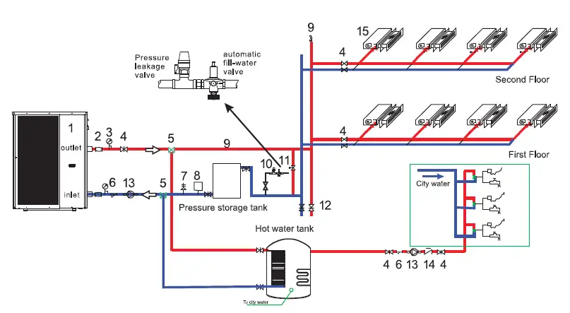
Install Sketch Map
Special Installation (Expandable Water Tank)
- Main Unit
- Connecting Hose
- Pressure Meter
- General Valve
- Three-way Valve
- Y-type Filter
- Safety Valve
- Expansion Tank
- Vent Valve
- Automatic Refill Valve
- Pressure Differential Bypass Valve
- Drain Valve
- Non-return Valve
- Water Pump
- Fan Coil
Automatic Filled Water Valve
When the automatic filled-water valve is installed, the arrowhead orientation of inlet water must accord with the orientation of the valve.
Automatic filled-water has been adjusted in advance to 1.5ba.
If readjusting the pressure of inlet water, please operate as follows:
- Open the Screw Cap ( C )
- If reducing the pressure of water supply, unscrew the pressure to adjust the screw (B)
- If increasing the pressure of water supply, screw down the pressure to adjust the screw (B)
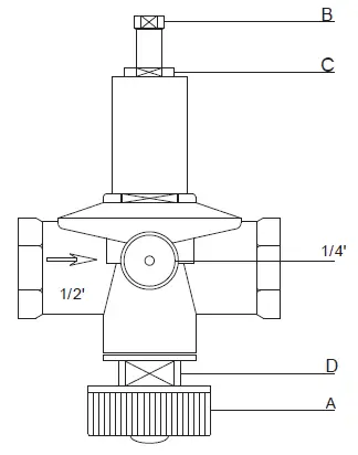
When the system needs to be filled with water at first, rest the handle (A) of filledwater. Then the handle (A) can return (close) when the system is full of water.
Automatic filled-water valve needs periodic cleaning. When you must close the tap, unscrew the plug (D), remove the inside filter net. Reassemble after cleaning.
NOTE: There are two connections for water pressure meters in the central section of automatic filled-water, where the water pressure meter can be connected directly and display the set pressure. The screw cap ( C ) must be tweaked after adjusting the filled-water pressure.
Leakage Pressure Valve
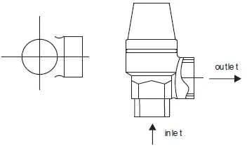
The action pressure of the leakage pressure valve is more than 3bar (valve is open), but the pressure cannot be adjusted.
The valve will open automatically to make sure that the water loop of air-con system is safe when the water pressure in the backwater side is higher than the set pressure.
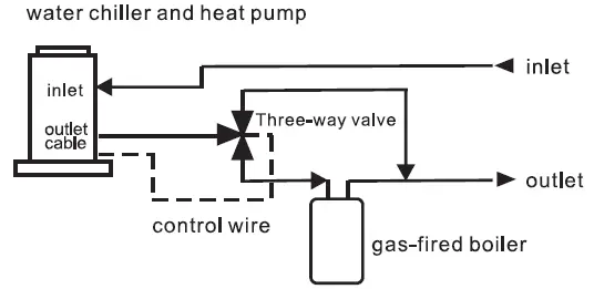
Assistant Heat Source Connection
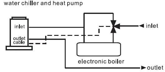
Unit provides the connection of assistant heat-source, which can be not only be for a gas fired boiler, but also for an electronic boiler or warm-net pipe for city accordingly.
Water Chiller & Heat Pump + Assistant Gas-Fired Boiler
Water Chiller & Heat Pump + Assistant Electronic Boiler
Cable Specifications
| Nameplate maximum current | Phase line (Single Phase) | Phase Line (Three Phase) | Earth line | MCB | Creepage Protector | Signal Line |
| No more than 10A | 2 x 1.5mm2 | 3 x 1.5mm2 | 1.5mm2 | 20A |
30mA less than 0.1 sec |
n x 0.5mm2 |
| 10~16A | 2 x 2.5mm2 | 3 x 2.5mm2 | 2.5mm2 | 32A | ||
| 16~25A | 2 x 4mm2 | 3 x 4mm2 | 4mm2 | 40A | ||
| 25~32A | 2 x 6mm2 | 3 x 6mm2 | 6mm2 | 40A | ||
| 32~40A | 2 x 10mm2 | 3 x 10mm2 | 10mm2 | 63A | ||
| 40~63A | 2 x 16mm2 | 3 x 16mm2 | 16mm2 | 80A | ||
| 63~75A | 2 x 25mm2 | 3 x 25mm2 | 25mm2 | 100A | ||
| 75~101A | 2 x 25mm2 | 3 x 25mm2 | 25mm2 | 125A | ||
| 101~123A | 2 x 35mm2 | 3 x 35mm2 | 35mm2 | 160A | ||
| 123~148A | 2 x 50mm2 | 3 x 50mm2 | 50mm2 | 225A | ||
| 148~186A | 2 x 70mm2 | 3 x 70mm2 | 70mm2 | 250A | ||
| 186~224A | 2 x 95mm2 | 3 x 95mm2 | 95mm2 | 280A |
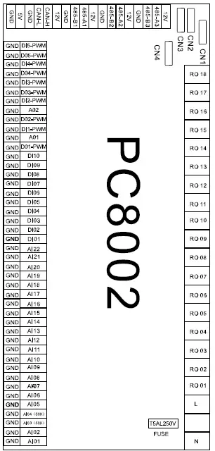
Controller Interface Diagram
| No. | Sign | Meaning |
| 01 | RO 01 | Compressor (output 220- 230VAC) |
| 02 | RO 02 | Water Pump (output 220- 230VAC) |
| 03 | RO 03 | 4-way valve (output 220- 230VAC) |
| 04 | RO 04 | Fan (output 220-230VAC) |
| 05 | RO 05 | Reserved |
| 06 | RO 06 | Anti-freezing heater (output 220-230VAC) |
| 07 | RO 07 | Crankshaft Heater (output 220- 230VAC) |
| 08 | RO 08 | Spray Valve (output 220- 230VAC) |
| 09 | RO 09 | Electric Auxiliary Heater (output 220-230VAC) |
| 10 | RO 10 | Reserved |
| 12 | RO 11 | Alarm (output 220-230VAC) |
| 12 | RO 12 | Hot Water Pump |
| 13 | RO 13 | Electromagnetic three-way valve |
| 14 | RO 14~RO18 | Reserved |
| 15 | AC-L | Live Wire (output 220-230VAC) |
| 16 | AC-N | Neutral Wire (output 220- 230VAC) |
| 17 | AI01 | Water Inlet Temperature (input) |
| 18 | AI02 | Water output temperature (input) |
| 19 | AI03 | System exhaust temperature (input) |
| 20 | AI04 | Reserved |
| 21 | AI05 | System suction temperature (input) |
| 22 | AI06 | System coil temperature (input) |
| 23 | AI07 | Ambient temperature (input) |
| 24 | AI08 | Water tank temperature (input) |
| 25 | AI09-AI20 | Reserved |
| 26 | AI21 | Suction pressure input |
| 27 | AI22 | Exhaust pressure input |
| 28 | DI01 | System high pressure (input) |
| 29 | DI02 | System low pressure (input) |
| 30 | DI03 | Water flow switch (input) |
| 31 | DI04 | Emergency switch (input) |
| 32 | DI05 | Mode switch (input) |
| 33 | DI06 | Master-slave machine switch (input) |
| 34 | DI07 | Electric heating overload protection switch (input) |
| 35 | 485_A1 | Frequency Conversion Board Communications |
| 36 | 485_B1 | Frequency Conversion Board Communications |
| 37 | 485_A2 | Communicate with wire controller and DC fan module |
| 38 | 485_B2 | Communicate with wire controller and DC fan module |
| 39 | 485_A3 | Reserved |
| 40 | 485_B3 | Reserved |
| 41 | 12V | 12V (output) |
| 42 | 5V | 5V (output) |
| 43 | CN1 | Electronic expansion valve |
| 44 | CN2-CN4 | Reserved |
Maintenance
DO I NEED TO GET MY UNIT SERVICED?
It is recommended that you get your EvoHeat unit serviced once a year by your local certified air conditioning or refrigeration technician. If your unit is located in a coastal area, more frequent maintenance may be necessary. During the service, they will check the operational pressures of the refrigeration system and give the unit and fins a good clean to ensure maximum performance.
DO WE HAVE RECOMMENDED SERVICE AGENTS?
EvoHeat have a large database of recommended service agents. Please contact EvoHeat tech support on 1300 859 933 for your local service agent detail
SHOULD I CHECK MY UNIT REGULARLY?
We recommend you check your unit regularly to avoid potential issues and damage to your heat pump.
Check the water inlet/outlets often for leaks. You should avoid the condition of no water or air entering into the system, as this will influence unit’s performance and reliability.
The area around the unit should be dry, clean and well ventilated. Make sure there is nothing blocking the airflow of the heater e.g. Leaf litter. Clean the heat exchanger every few months to keep a good heat exchange rate and save energy.
WHAT SHOULD I BE CHECKING REGULARLY?
You should discharge the water at the bottom of the water pump if the unit will not be used for an extended period. Discharge all water in the water pump and water system so that freezing of the water in the pump or water system does not occur.
Check the unit thoroughly and fill the system with water fully before using it for the first time after a period of time.
Check the power supply and cable connection often, should the unit begin to operate abnormally, switch it off and contact the qualified technician
Clean the water filter periodically to maintain good water quality. Lack of water and dirty water can damage the unit. The heat pump will start the water every 72 hours when it is not running to avoid freezing.
The water loop of the heat pump MUST be protected from freezing in winter. Do not shut off the power supply to the heat pump in winter. When the air temperature is below 0°C, if the inlet water temperature is above 2°C and below 4°C the water pump will begin freezing protection. If the inlet water is lower than 2°C, the heat pump will begin heating.
Warranty
Refer to the EvoHeat website for warranty details
- Australia: https://evoheat.com.au/warranty-terms/
- South East Asia: http://evoheat.com.sg/warranty/
- Warranty terms are from date of purchase.
- This warranty excludes any defect or injury caused by or resulting from misuse, abuse, neglect, accidental damage, improper voltage, vermin infestation, incompetent installation, any fault not attributable to faulty manufacture or parts, any modifications which affect the reliability or performance of the unit.
- This warranty does not cover the following:
a. Natural Disasters (hail, lightening, flood, fire etc.)
b. Rust or damage to paintwork caused by a corrosive atmosphere
c. When serviced by an unauthorized person without the permission of Evo Industries
d. When a unit is installed by an unqualified person
e. Where a unit is incorrectly installed
f. When failure occurs due to improper or faulty installation
g. Failure due to improper maintenance (refer Operating Instructions)
h. ‘No Fault Found’ service calls where the perceived problem is explained within the
i. Costs associated with delivery, handling, freighting, or damage to the product in transit. - If warranty service is required, you should:
a. contact Evo Industries Australia on 1300 859 933 or via our Contact page on our web site
b. provide a copy of your receipt as proof of purchase
c. have completed the online Warranty Registration Form - Onsite technical service is available within the normal operating area of your Evo Authorised Service Agents. Service outside this area will incur a traveling fee.
- Unless otherwise specified to the purchaser, the benefits conferred by this express warranty and additional to all other conditions, warranties, rights and remedies expressed or implied by the Trade Practices Act 1974 and similar consumer protection provisions contained in legislation of the States and Territories and all other obligations and liabilities on the part of the manufacturer or supplier and nothing contained herein shall restrict or modify such rights, remedies, obligations or liabilities.
REGISTER YOUR WARRANTY
EvoHeat highly recommend customers complete their warranty details online to ensure efficient warranty claim processing.
To register your warranty, scan our QR Code or head to our website and fill in the Warranty Registration Form: https://evoheat.com.au/warranty-registration/
[email protected]
1300 859 933
www.evoheat.com.au


