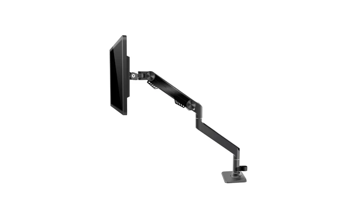
American Express MU7005 Premium Single Monitor Stand Instruction Manual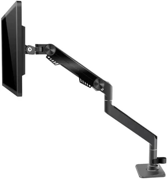
SAFETY INSTRUCTIONS
BEFORE ASSEMBLY
- Layout all components and hardware. Check all parts are included and undamaged.
- Should anybody intends to install or use this monitor arm, please read and understand this manual carefully
WARNING
- This product contains small items that could be a choking hazard if swallowed.
- KEEP AWAY FROM CHILDREN UNDER 3 YEARS OLD. ADULT SUPERVISION IS REQUIRED.
- Improper installation, such as using the product for monitors over its load capacity or for any purpose not explicitly specified, may cause damage or serious injury. We would not be liable for any damage or injury caused by improper mounting or inappropriate use.
- If you do not understand these instructions or have any doubt about the safety instructions, assembly or use of this product, please contact our customer service.
PACKAGE CONTENTS
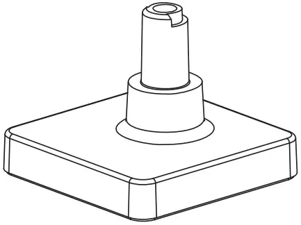
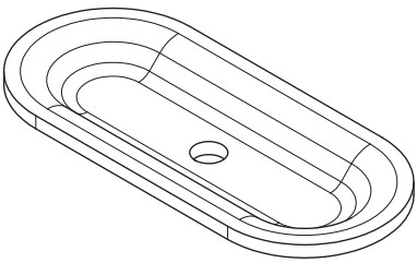
- 5 (×1) Base

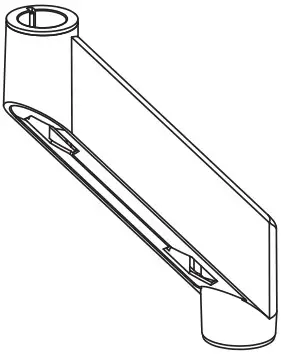
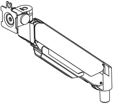
- 6 (×1) Lower arm

- 7 (×1) Upper arm

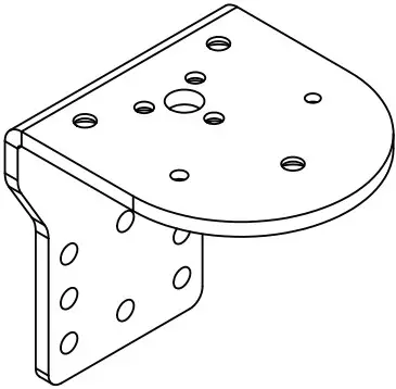
- 8 (×1) Bracket

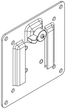
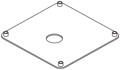
- 9 (×1) VESA plate

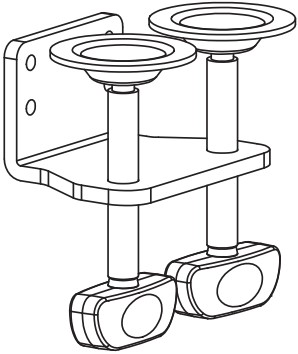
- 10 (×1) Clamp

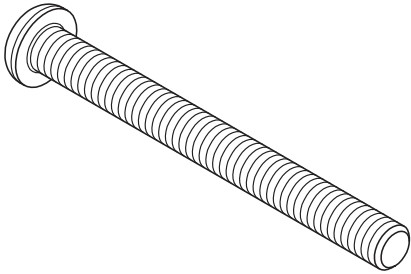
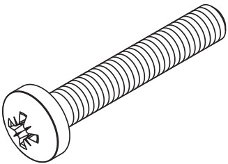
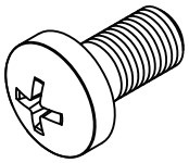
- 11 (×1) Long Bolt

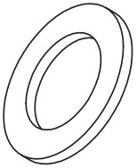
- 12 (×1) Washer

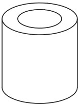
- 13 (×1) Cushion

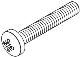
- 1 (×4) Screw M4×25

- 2 (×4)Screw M5×25|

- 3 (×4)Washer

- 4 (×4)Spacer H15mm

- A (×4) Screw M4x10

- B (×4) Screw M5x10

- C (×3) bolt M6×12

- D (×4) bolt M6×10

- E (×1) M5×20

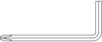
- F(×1)4mm Allen Key

- G (×1)5mm Allen Key

- H(×1)6mm Allen Key

DO NOT EXCEED WEIGHT CAPACITY.
Clamp Installation OR Grommet Base Installation
OPTION A: Clamp Installation
Mount Bracket (8) to Base (5) with Bolts (C). Bolts could be tightened by the 4mm Allen Key (F). Install the cushion (13) on the base (5) to avoid scratching the table top.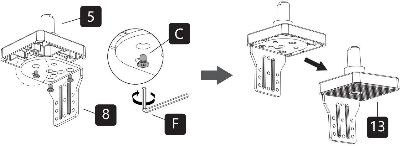
There are two sets of key slot holes to choose from for different desktop thicknesses. Attach Clamp (10) to Bracket (8) with Bolts (D) then tighten them with 4mm Allen key (F).
For Desks 0.39” to 2.56” use the top four holes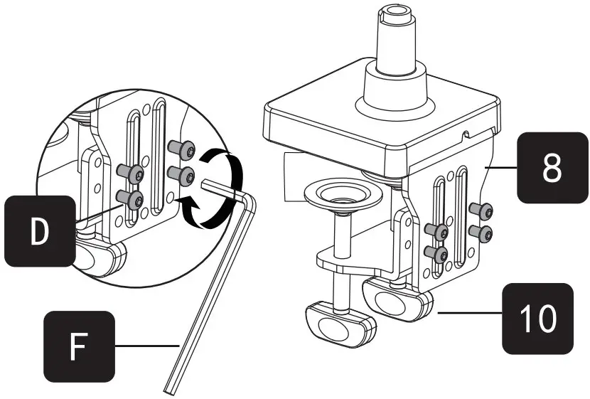
For Desks 1.18” to 3.15” use the bottom four holes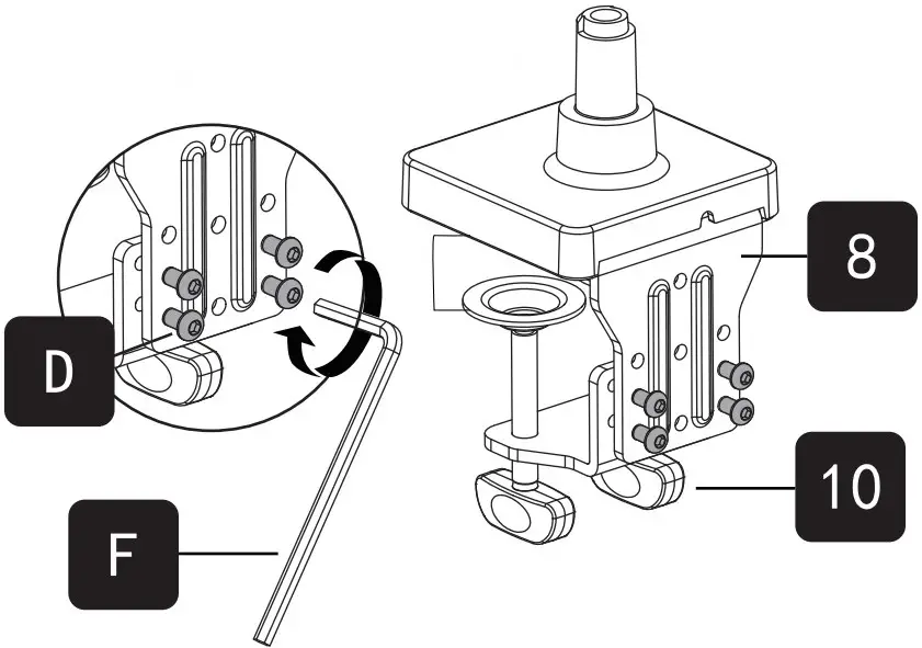
Adjust the Clamp width to fit with desk.
Secure stand to desktop by tightening Clamp or by Allen key (G).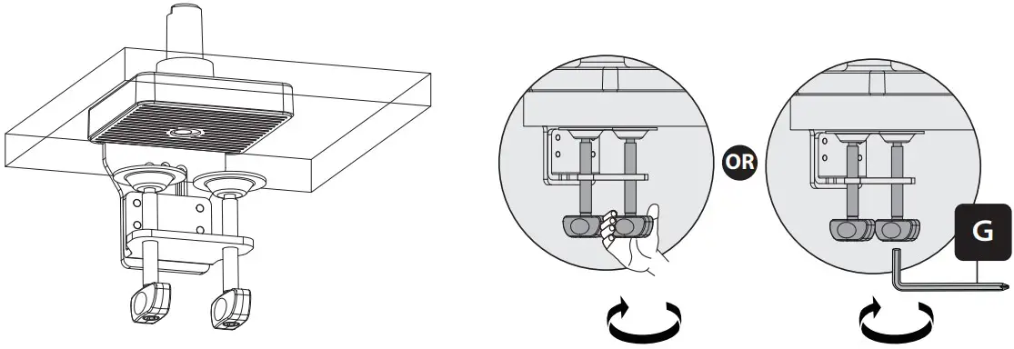
Continued
OPTION B: Grommet Base Installation
Ensure the desktop has a hole between 0.4” and 2.4” in diameter to use this option. Using a grommet hole that is already in your desktop is acceptable.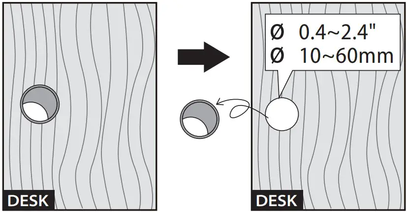
Install the cushion (13) on the base (5) to avoid scratching the table top.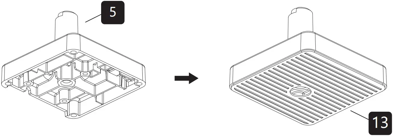
Insert the long bolt (11) through the washer (12) and the hole on the table top, and then use the Allen key (H) to tighten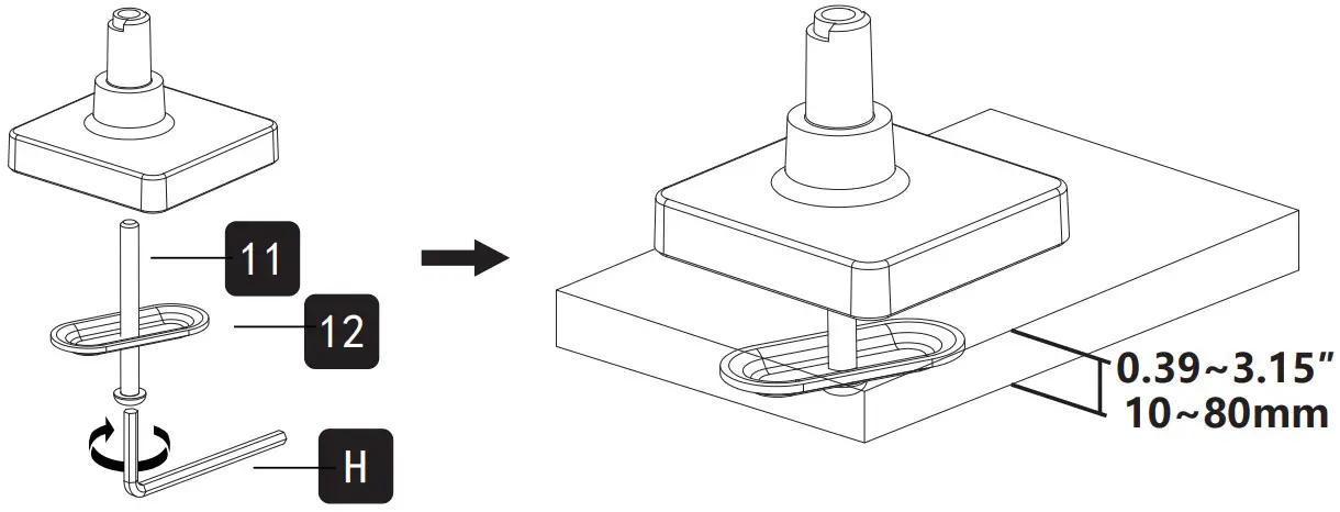
Arm Installation
Connect the upper arm (7) and the lower arm (6) with the screw (E) through the rivet nut, and tighten it with an Allen key (F).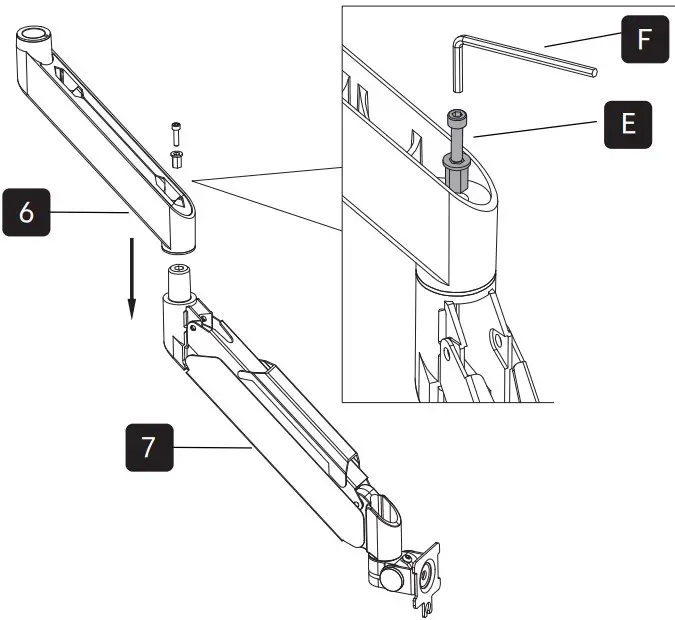
![]() WARNING:
WARNING:
- Tighten the screws (E) on the Lower Arm and this will prevent the Upper Arm from becoming separated from the Lower Arm during adjustment.
- Please don’t use any drills it will damage the screw.
Insert the lower arm into the base and adjust the screw with the Allen key (F) to fix the lower arm.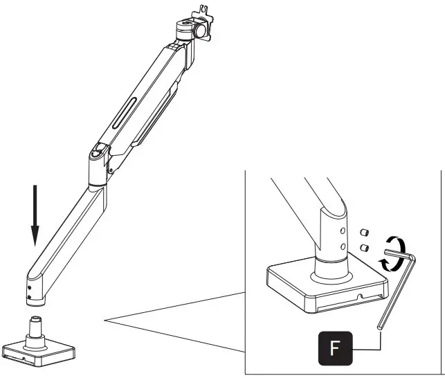
- The Top Screw
OPTION A: If you want to swivel ±180°, just loosen the top screw.
OPTION B: If you want to swivel ±90°, just lock the top screw. - The Lower Screw
The lower screw are used to adjust the tightness of the connection between the base and the bracket arm to avoid the arms from shaking.
The screws on the top are used to limit the position.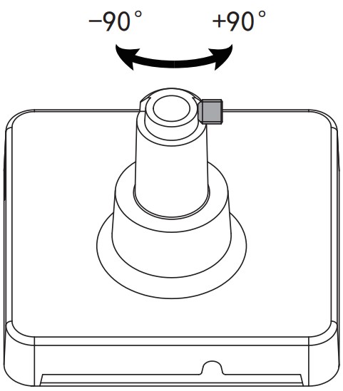
Attach Monitor
OPTION A: Flat Back Monitor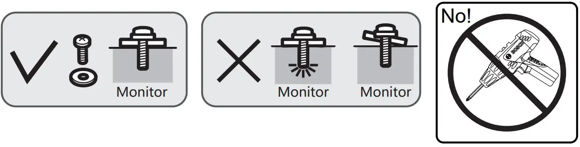
Attach the VESA plate (9) to the back of monitor and secure it by using a 5mm Allen Key (G) to tighten screws (A or B) along with washers (3).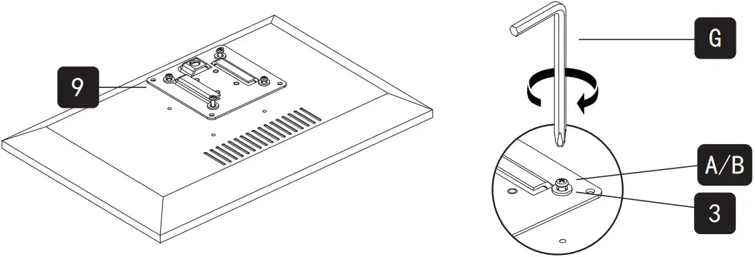
![]() Do not tighten the screws excessively or your monitor might be damaged.
Do not tighten the screws excessively or your monitor might be damaged.
OPTION B: Curved / Recessed Back Monitor
Attach the VESA plate (9) to the back of monitor and secure it by using a 5mm Allen Key (G) to tighten screws (1 or 2) along with washers (3) and spacers (4).
![]() Do not tighten the screws excessively or your monitor might be damaged.
Do not tighten the screws excessively or your monitor might be damaged.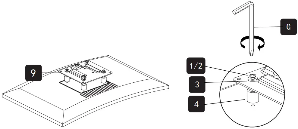
Hang Monitor
Slide the monitors onto the head of arm.
Lock the security knob. Make sure the security knob is locked before you rotate the monitor.
When the display is inserted into the quick release head, make sure the knob is vertical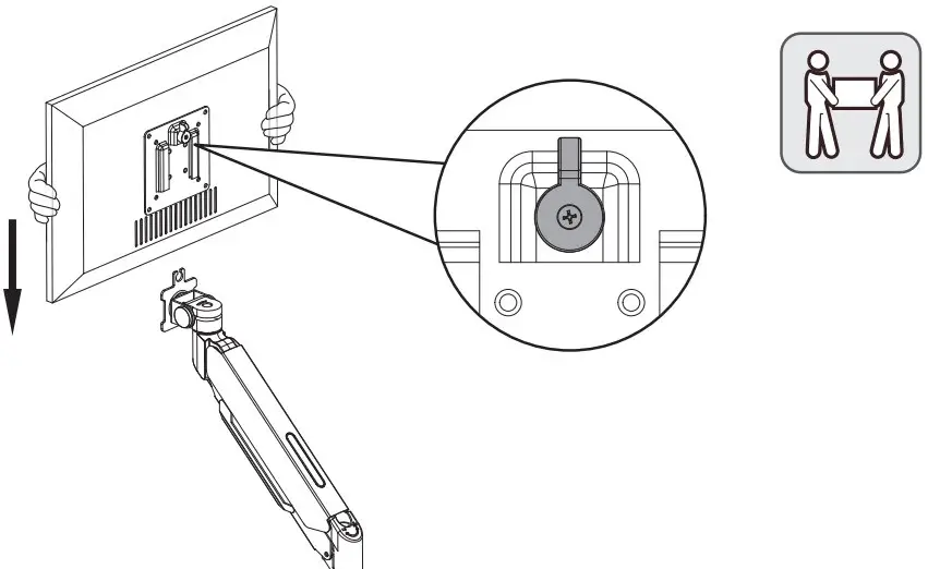
After insertion, rotate the knob 90 degrees to the left.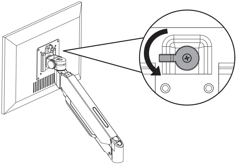
![]() Important Notice:
Important Notice:
The pressure of the gas spring is initially set to an intermediate value. So when the monitor hangs, make sure to hold it with both hands and don’t let it drop suddenly.
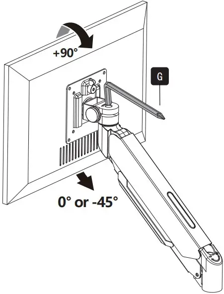
Adjust monitor tilting angle
![]() Turn clockwise to tighten
Turn clockwise to tighten![]() Turn counterclockwise to loose
Turn counterclockwise to loose

Limit screw can prevent the head from sinking. This screw can be removed when you need the display to be lowered (0°~-45°).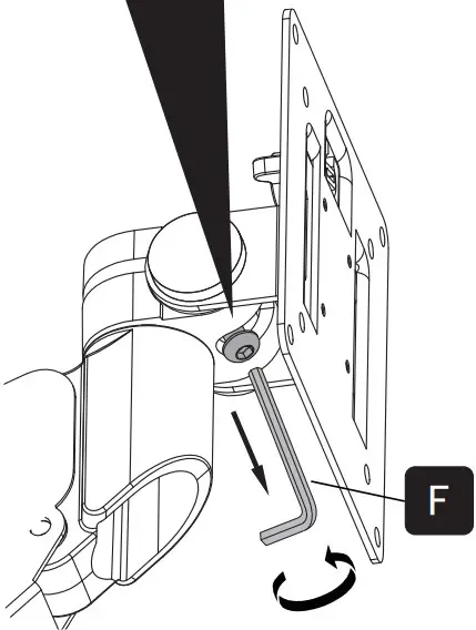
Before removing the screw +90°~0°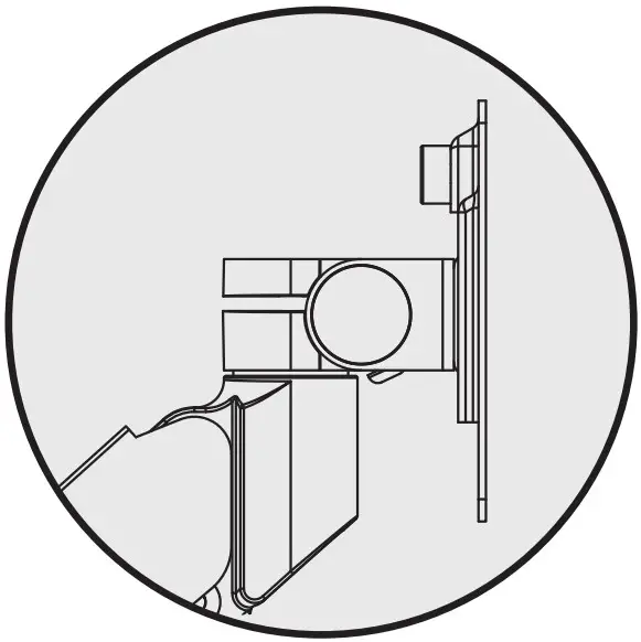
After removing the screw +90°~-45°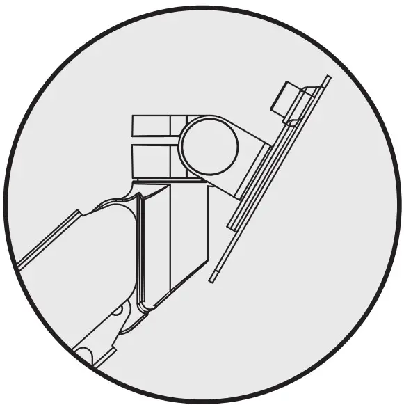
Adjust Gas Spring Tension
For proper functioning of this mount, depending on different weight of monitor you might need to adjust tension in upper arm (7) using 6mm Allen Key (H).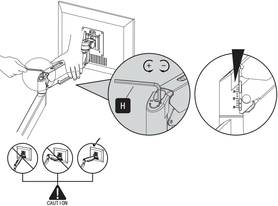
The initial value of the scale is the middle value of the force range. The force value of the gas spring can be understood through the scale, which is convenient for modification
Note:
Be sure to keep the arm in horizontal position during adjustment. Or else it would be dicult to adjust the mount or damage the mount.

Situation 1: Arm falls down
Upper Arm with monitor falls down and fails to stay where intended.
Solution:
Turn the inside screw counterclockwise (“+”direction) to increase gas spring tension until the arm can stay as intended.

Situation 2: Arm rises up / can’t be pressed down
Upper Arm with monitor rises up automatically or can’t be pressed down and fails to stay where intended.
Solution:
Turn the inside screw clockwise (“-”direction) to decrease gas spring tension until the arm can stay as intended.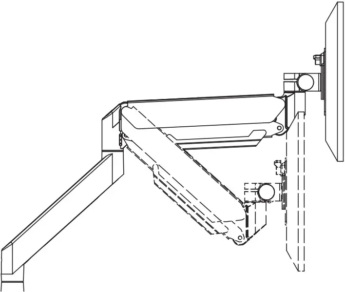
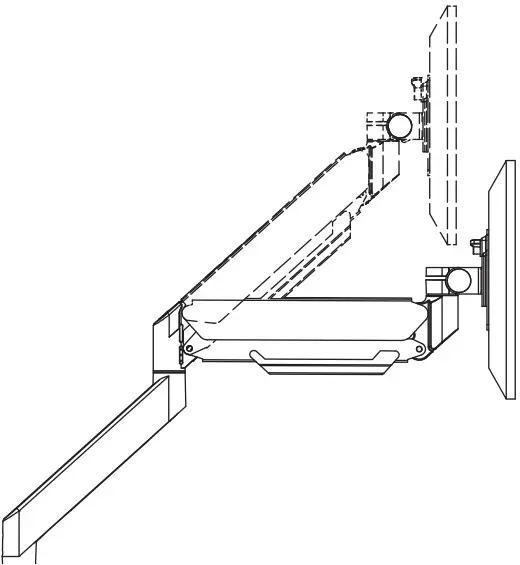
Cable Management
Remove Cable Cover
Remove the cable cover by grasping both sides of one end of the cover with the fingers of both hands, and then pulling it to the left and right respectively.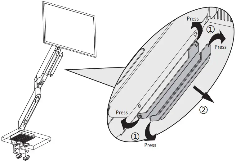
Attach Cable Cover
Run cables from monitor through bottom of arm. Reattach plastic covers as shown in diagram.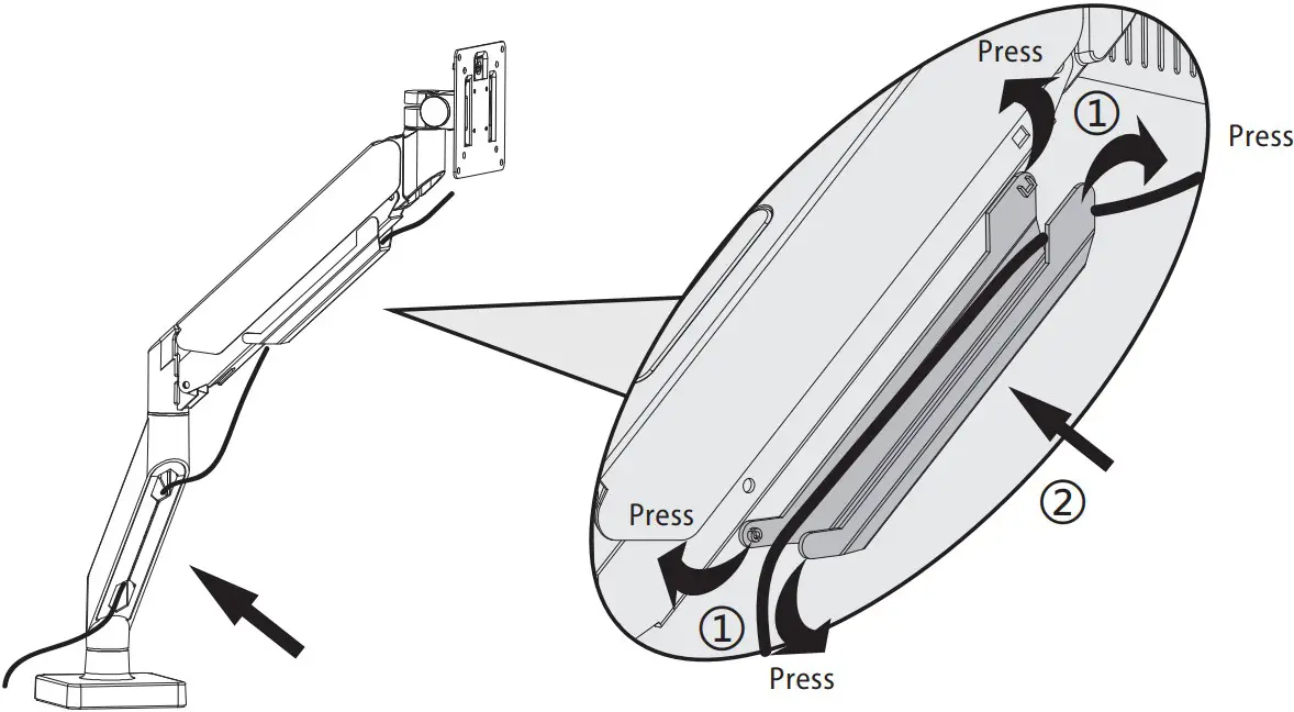
Adjust as Desired
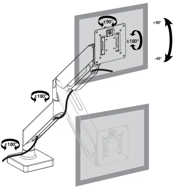
Adjust monitor position and rotation.
![]() Tilt
Tilt![]() Swivel
Swivel![]() Rotation
Rotation![]() Height
Height
Note: To ensure stability, the tightness of the rotating axis has been preseted, so it would be kind of dificult to rotate the VESA plate.
Suggestion: Please attach the monitor first, then hold the two sides of it with both hands, and rotate vigorously. If that doesn’t work out, please do not hesitate to ask for our help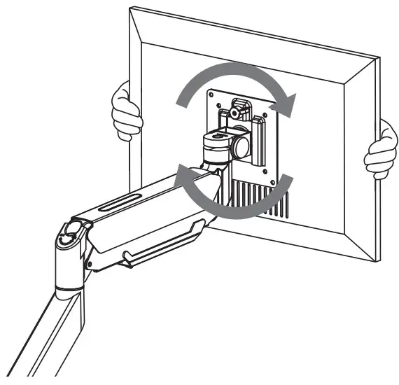
WARNING:
For your safety, do not move the stand off your desk!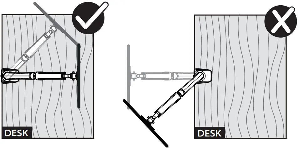
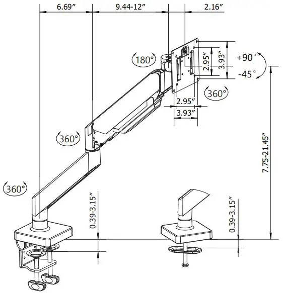
Product Dimensions
![]() CAUTION AND MAINTENANCE:
CAUTION AND MAINTENANCE:
- Never allow children to climb, stand, hang, or play on any part of monitor or stand.
- This product is intended for indoor use only. Using this product outdoors could lead to product failure and personal injury.
- Check that the bracket is secure and safe to use at regular intervals (at least every three months)