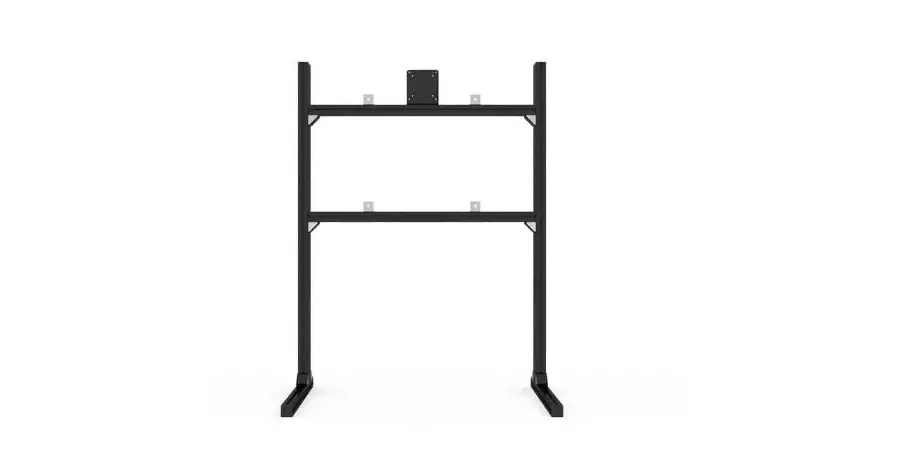
SIM LAB SLT010 Single Monitor-TV Stand
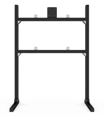
Product Information
| Part No. | Part Name | Quantity | Unit of Measure | Note |
|---|---|---|---|---|
| A1 | Profile 40mm slot 8 (Black, 40x80L) – 1195mm | 2 | Units | |
| A2 | Profile 40mm slot 8 (Black, 40x40L) – 850mm | 2 | Units | |
| A3 | Profile 40mm slot 8 (Black, 40x40L) – 580mm | 2 | Units | |
| B1 | VESA 75/100 bracket, aluminium, 5mm, black | 8 | Units | |
| B2 | Corner bracket 40×40 + Cover cap | 3 | Units | |
| B3 | End cap profile (40x40L) | 4 | Units | |
| B4 | End cap profile (40x80L) | 2 | Units | |
| B5 | ELOX corner bracket – slot 8 mm | 4 | Units | |
| B6 | Rubber feet | 4 | Units | |
| B7 | Bolt – DIN 912 (Galvanised, 16mm, M8) | 24 | Units | |
| B8 | Bolt – DIN 912 (Black steel, 16mm, M6) | 2 | Units | |
| B9 | Bolt – DIN 912 (Black steel, 20mm, M6) | 4 | Units | |
| B10 | Phillips head screw – DIN 7985 (10mm) | 4 | Units | |
| B11 | Phillips head screw – DIN 7985 (16mm) | 4 | Units | |
| B12 | Spacer – male / female (10mm, M4) | 4 | Units | |
| B13 | Washer (Black steel, M8, plain black) | 6 | Units | |
| B14 | Slot 8 nut (M6) | 20 | Units | |
| B15 | Slot 8 nut (M8) | 24 | Units |
Product Usage Instructions
- Start by assembling the feet and uprights using the following parts: B1, A1, A3, B3, B6, and B9. Refer to the provided diagram for proper assembly.
- Next, assemble the crossbars using parts A2, B2, B7, and B15. Again, refer to the diagram for correct assembly.
- If your monitor has a VESA mount larger than 100×100, use the VESA assembly parts A, B7, and B15. Follow the instructions provided in the diagram.
- If your monitor has a VESA mount of 75×75 or 100×100, use the VESA assembly parts A, B8, B14, and B1. Refer to the diagram for guidance.
- Refer to the parts list to ensure you have all the necessary components for assembly.
- Optional: Use the provided spacers if your VESA panel on the monitor is inset.
SKU: SLT010
https://sim-lab.eu/shop/product/single-monitor-tv-stand-654
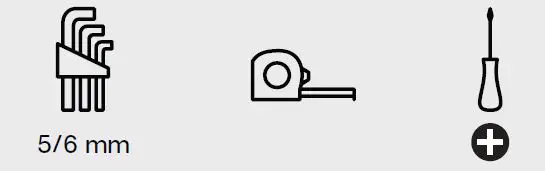
Required tools
STEP 1
Feet and upright assembly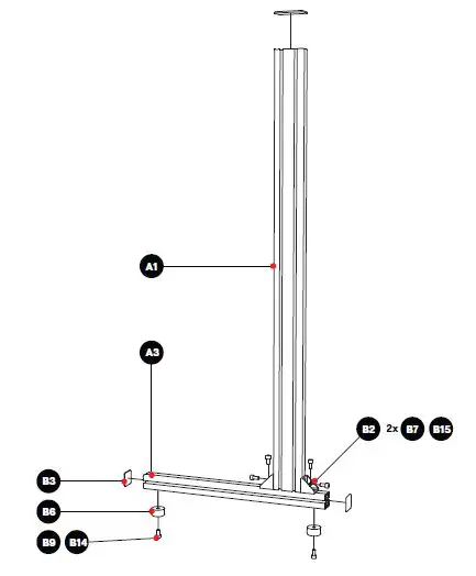
STEP 2
Crossbar assembly 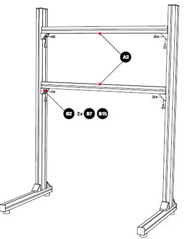
STEP 3
VESA assembly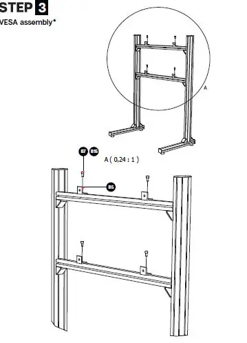
- Used for VESA mounts larger than 100×100 (e.g. 200×200, 200×300, 300×300, 400×400)4 B7 B15 B5
STEP 4
VESA assembly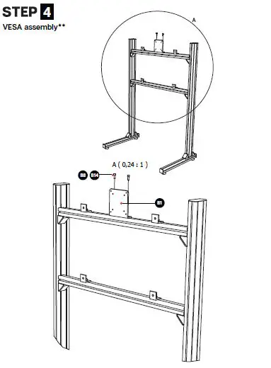 Used for 75×75 and 100×100 VESA mounts
Parts list
Profile kit
- Part No. Part name QTY UoM Note
- A1 Profile 40mm slot 8 (Black, 40x80L) – 1195mm 2 Units Uprights
- A2 Profile 40mm slot 8 (Black, 40x40L) – 850mm 2 Units Crossbars
- A3 Profile 40mm slot 8 (Black, 40x40L) – 580mm 2 Units Feet
Hardware kit
- Part No. Part name QTY UoM : Note
- B1 VESA 75/100 bracket, aluminium, 5mm, black 8 Units : Optional, for use on 75×75 and 100×100 VESA
- B2 Corner bracket 40×40 + Cover cap 3 Units
- B3 End cap profile (40x40L) 4 Units
- B4 End cap profile (40x80L) 2 Units
- B5 ELOX corner bracket – slot 8 mm 4 Units
- B6 Rubber feet 4 Units
- B7 Bolt – DIN 912 (Galvanised, 16mm, M8) 24 Units
- B8 Bolt – DIN 912 (Black steel, 16mm, M6) 2 Units
- B9 Bolt – DIN 912 (Black steel, 20mm, M6) 4 Units
- B10 Phillips head screw – DIN 7985 (10mm) 4 Units For attaching monitor to ELOX/VESA plate, shorter
- B11 Phillips head screw – DIN 7985 (16mm) 4 Units For attaching monitor to ELOX/VESA plate, longer
- B12 Spacer – male / female (10mm, M4) 4 Units Spacers for offset, if VESA panel on monitor is inset
- B13 Washer (Black steel, M8, plain black) 24 Units
- B14 Slot 8 nut (M6) 6 Units
- B15 Slot 8 nut (M8) 20 Units


