velleman K8033 Power Blinker
Features
- Separate adjustment for ON- and OFF-time with LED indication. þSuited for most slightly inductive loads.
- Ideally suited for e.g. safety signs, disco lights, etc…
- Noise suppressed according to EN55015.
Specifications
- AC Power : 110 to 240 VAC.
- Auto frequency detection : 50/60Hz.
- Max load per channel 1A : 125W (110 – 125VAC) 250W (220 – 240VAC)
- whit optional heatsink 3A : 300W (110 – 125VAC) 600W 220 – 240VAC)
- ON-time adjustable between : 50ms and 2,5sec.
- OFF-time adjustable between : 0,5sec. and 15sec.
- Dimensions : 100 x 82 x 35mm / 4 x 3,3 x 1,4”
Assembly (Skipping this can lead to troubles ! )
Ok, so we have your attention. These hints will help you to make this project successful. Read them carefully.
Make sure you have the right tools
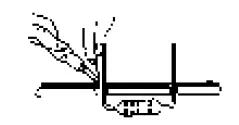
- A good quality soldering iron (25- 40W) with a small tip.
- Wipe it often on a wet sponge or cloth, to keep it clean; then apply solder to the tip, to give it a wet look. This is called ‘thinning’ and will protect the tip, and en-ables you to make good connections. When solder rolls off the tip, it needs cleaning.
- Thin raisin-core solder. Do not use any flux or grease.

- A diagonal cutter to trim excess wires. To avoid injury when cutting excess leads, hold the lead so they cannot fly towards the eyes.
- Needle nose pliers, for bending leads, or to hold components in place.
- Small blade and Phillips screwdrivers. A basic range is fine.
For some projects, a basic multi-meter is required, or might be handy
Assembly Hints
- Make sure the skill level matches your experience, to avoid disappointments.
- Follow the instructions carefully. Read and understand the entire step before you perform each operation.
- Perform the assembly in the correct order as stated in this manual
- Position all parts on the PCB (Printed Circuit Board) as shown on the drawings.
- Values on the circuit diagram are subject to changes.
- Values in this assembly guide are correct*
- Use the check-boxes to mark your progress.
- Please read the included information on safety and customer service
* Typographical inaccuracies excluded. Always look for possible last minute manual updates, indicated as ‘NOTE’ on a separate leaflet.
Soldering Hints
Mount the component against the PCB surface and carefully solder the leads
Make sure the solder joints are cone-shaped and shiny
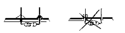
Trim excess leads as close as possible to the solder joint 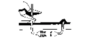
AXIAL COMPONENTS ARE TAPED IN THE CORRECT MOUNTING SEQUENCE !
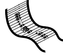
REMOVE THEM FROM THE TAPE ONE AT A TIME ! 
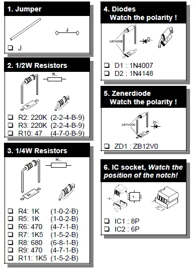
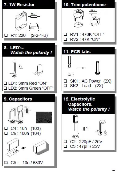
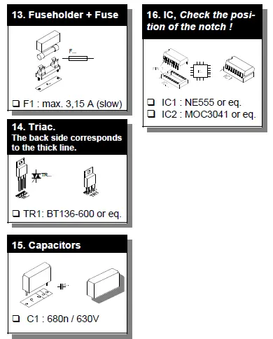
Construction
Hook– up and use
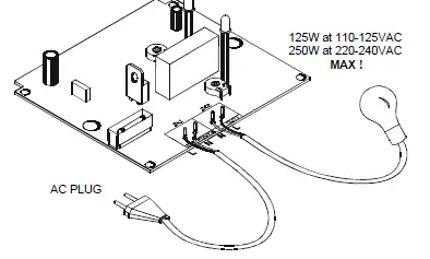
Solder an AC cable to the SK1 pins (AC Power).
Solder the cables of the lampholder to the appropriate pins “SK2”(LOAD), use always min. ø 0,75mm² cable.
As this kit is shipped to different countries, their is no AC plug supplied. You will need to attach a plug that matches your electrical system. You can adjust the ON/OFF time by turning the trimmer RV1 “OFF” and RV2 “ON”. The ON/OFF LEDs indicate the LOAD status.
FThe connection cables should be equipped with a good strain relief when mounted in a movable housing. FOptional you can mount a heatsink on TR1 (e.g. ML73/25P) so that Max. power is 600W at 240VAC and 300W at 110VAC.
Inspect the complete assembly once more before applying power to the unit !
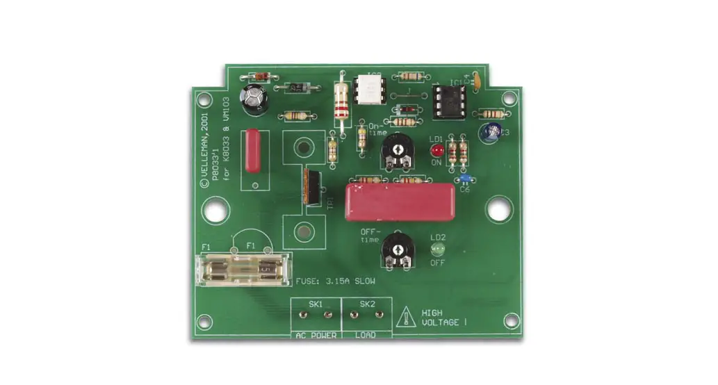
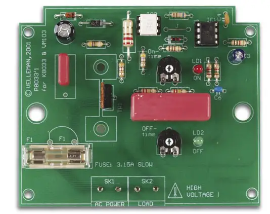
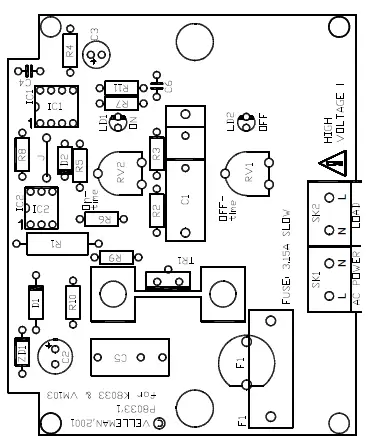
PCB layout
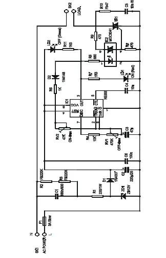
Schematic diagram
VELLEMAN Components NV Legen Heirweg 33
9890 Gavere
Belgium Europe
www.velleman.be
www.velleman-kit.com


