![]() Total solder points: 293
Total solder points: 293
Difficulty level:
beginner 1o 2o 3þ 4o 5oadvanced
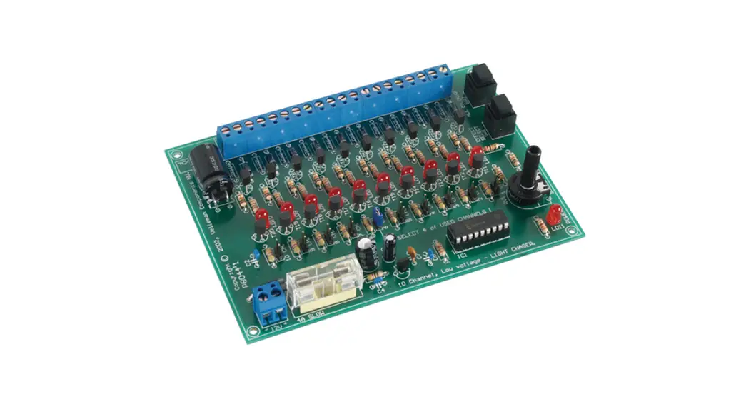
12V, Ten channel light effect generator
K8044
Features:
- Ten, 12V/400mA outputs.
- To control cold-cathode fluorescent lamps (using FLPS adapter), light bulbs, LED’s and “solid state” relays, …
- For use as advertisement lighting, party lights, discos, eye-catcher,…
- Ten pre-programmed light patterns selectable with a push button.
- The number of used channels is adjustable.
- Adjustable speed.
- Led indication for every output.
- 12V operation possible for use in cars.
Specifications :
- Power supply : 12V DC
- Outputs : 12V DC/400mA per channel (Total : max 4A)
- Dimensions : 140 x 100 x 27mm / 5,5 x 3,9 x 1,1”
Options (Velleman ordernumbers) :
- Power supply for cold-cathode fluorescent lamps : FLPS (300mm) or FLPS1 (100mm)
- Cold-cathode fluorescent lamps : FL(xx) – (100 or 300mm).
Modifications reserved.
VELLEMAN Components NV
Legen Heirweg 33 9890 Gavere
Belgium Europe
www.velleman.be
www.velleman-kit.com
- Assembly (Skipping this can lead to troubles ! )
Ok, so we have your attention. These hints will help you to make this project successful. Read them carefully.
1.1 Make sure you have the right tools:
- A good quality soldering iron (2540W) with a small tip.
- Wipe it often on a wet sponge or cloth, to keep it clean; then apply solder to the tip, to give it a wet look. This is called ‘thinning’ and will protect the tip, and enables you to make good connections.
- When solder rolls off the tip, it needs cleaning.
- Thin raisin-core solder. Do not use any flux or grease.

- A diagonal cutter to trim excess wires. To avoid injury when cutting excess leads, hold the lead so they cannot fly towards the eyes.

- Needle nose pliers, for bending leads, or to hold components in place.

- Small blade and Phillips screwdrivers. A basic range is fine.


![]() For some projects, a basic multi-meter is required, or might be handy
For some projects, a basic multi-meter is required, or might be handy
- Make sure the skill level matches your experience, to avoid disappointments.
- Follow the instructions carefully. Read and understand the entire step before you perform each operation.
- Perform the assembly in the correct order as stated in this manual
- Position all parts on the PCB (Printed Circuit Board) as shown on the drawings.
- Values on the circuit diagram are subject to changes.
- Values in this assembly guide are correct*
- Use the check-boxes to mark your progress.
- Please read the included information on safety and customer service
* Typographical inaccuracies excluded. Always look for possible last minute manual updates, indicated as ‘NOTE’ on a separate leaflet.
1.3 Soldering Hints :”
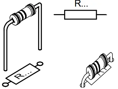
Mount the component against the PCB surface and carefully solder the leads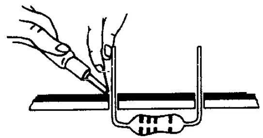
Make sure the solder joints are cone-shaped and shiny
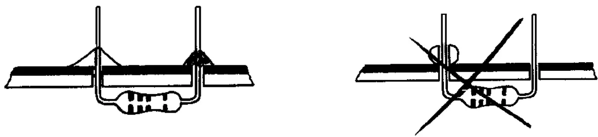
Trim excess leads as close as possible to the solder joint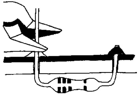
AXIAL COMPONENTS ARE TAPED IN THE CORRECT MOUNTING SEQUENCE !
REMOVE THEM FROM THE TAPE ONE AT A TIME ! 
| COLOURCODE | |
| Black | Yellow |
| Brown | Green |
| Red | Blue |
| Orange | Purple |
| Grey | Silver |
| White | Gold |
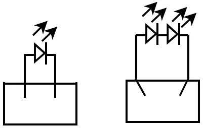
1. Jumper
- CH… : depending on the number of channels
- RX ‘∗’
‘∗ ’ATTENTION :
In case you use light bulbs, Cold-Cathode fluorescent lamps & “solid-state” relays mount for RX a jumper wire, If using LED’s as output indication then mount for RX a resistor appropriated to the value of the LED. See step 2.
2. Resistors ‘RX’
RX (for each output)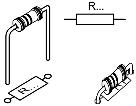
| Type of LED | ||
| Standard (Red) | 1K | 820 |
| White | 470 | 330 |
| Yellow / Green | 1K | 820 |
| Blue | 470 | 390 |
These resistors are not supplied whit this kit!
Resistors
- R1 : 10K (1-0-3-B)
- R2 : 10K (1-0-3-B)
- R3 : 10K (1-0-3-B)
- R4 : 10K (1-0-3-B)
- R5 : 10K (1-0-3-B)
- R6 : 10K (1-0-3-B)
- R7 : 10K (1-0-3-B)
- R8 : 10K (1-0-3-B)
- R9 : 10K (1-0-3-B)
- R10 : 10K (1-0-3-B)
- R11 : 270 (2-7-1-B)
- R12 : 270 (2-7-1-B)
- R13 : 270 (2-7-1-B)
- R14 : 270 (2-7-1-B)
- R15 : 270 (2-7-1-B)
- R16 : 270 (2-7-1-B)
- R17 : 270 (2-7-1-B)
- R18 : 270 (2-7-1-B)
- R19 : 270 (2-7-1-B)
- R20 : 270 (2-7-1-B)
- R21 : 4K7 (4-7-2-B)
- R22 : 4K7 (4-7-2-B)
- R23 : 4K7 (4-7-2-B)
- R24 : 4K7 (4-7-2-B)
- R25 : 4K7 (4-7-2-B)
- R26 : 4K7 (4-7-2-B)
- R27 : 4K7 (4-7-2-B)
- R28 : 4K7 (4-7-2-B)
- R29 : 4K7 (4-7-2-B)
- R30 : 4K7 (4-7-2-B)
- R31 : 47 (4-7-0-B)
- R32 : 3K3 (3-3-2-B)
- R33 : 10K (1-0-3-B)
- R34 : 10K (1-0-3-B)
- R35 : 10K (1-0-3-B)
- R36 : 330 (3-3-1-B)
Diodes. Watch the polarity !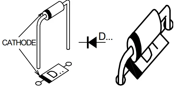
- D1 : 1N4007
- D2 : 1N4007
- D3 : 1N4007
- D4 : 1N4007
- D5 : 1N4007
- D6 : 1N4007
- D7 : 1N4007
- D8 : 1N4007
- D9 : 1N4007
- D10 : 1N4007
- D11 : 1N4007
- D12 : 1N5404
Pushbuttons.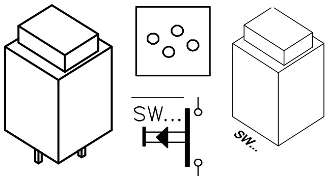
- SW1 : S500
- SW2 : S500
Voltage Regulator.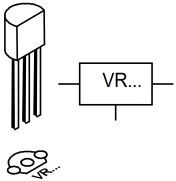
- VR1: UA78L05
IC socket, Watch the position of the notch!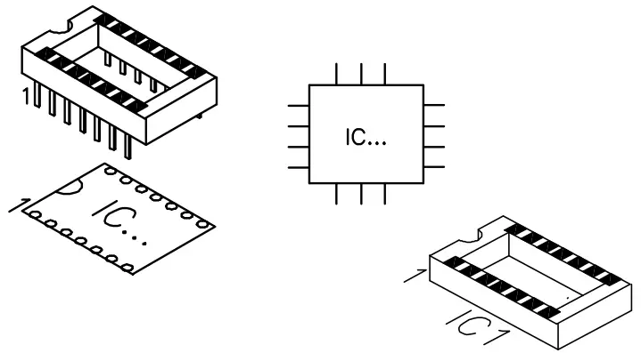
- IC1 : 18P
LED. Watch the polarity !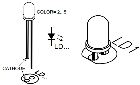
- LD1 : 5mm Red
- LD2 : 5mm Red
- LD3 : 5mm Red
- LD4 : 5mm Red
- LD5 : 5mm Red
- LD6 : 5mm Red
- LD7 : 5mm Red
- LD8 : 5mm Red
- LD9 : 5mm Red
- LD10 : 5mm Red
- LD11 : 5mm Red
Ceramic Capacitors
- C2 : 100nF (104)
- C4 : 100nF (104)
- C6 : 100nF (104)
- C7 : 100pF (101)
Transistors.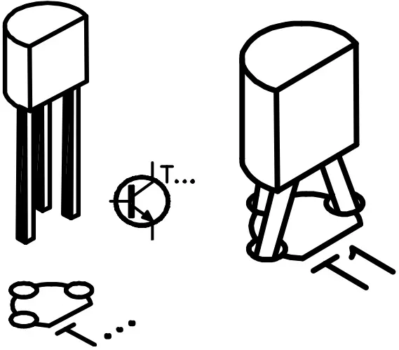
- T1 : BC640
- T2 : BC640
- T3 : BC640
- T4 : BC640
- T5 : BC640
- T6 : BC640
- T7 : BC640
- T8 : BC640
- T9 : BC640
- T10 : BC640
- T11 : BC547B
- T12 : BC547B
- T13 : BC547B
- T14 : BC547B
- T15 : BC547B
- T16 : BC547B
- T17 : BC547B
- T18 : BC547B
- T19 : BC547B
- T20 : BC547B
Electrolytic capacitors.
Watch the polarity ! 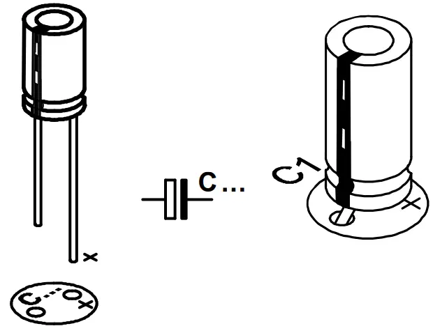
- C5 : 10µF
- C3 : 220µF
- C1 : 1000µF / 25V
Trim potentiometer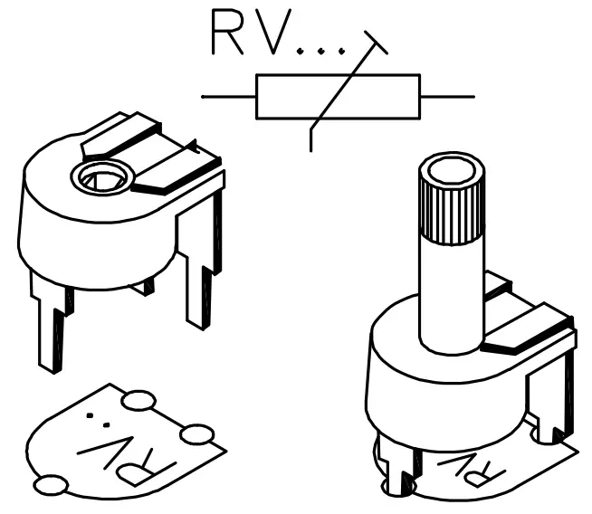
- RV1 : 100K
Terminal block connectors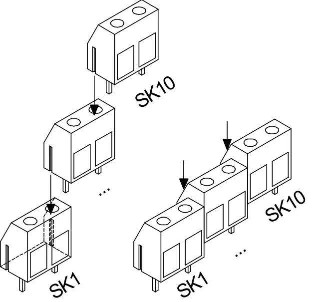
- SK1 : CH1 (2p)
- SK2 : CH2 (2p)
- SK3 : CH3 (2p)
- SK4 : CH4 (2p)
- SK5 : CH5 (2p)
- SK6 : CH6 (2p)
- SK7 : CH7 (2p)
- SK8 : CH8 (2p)
- SK9 : CH9 (2p)
- SK10 : CH10 (2p)
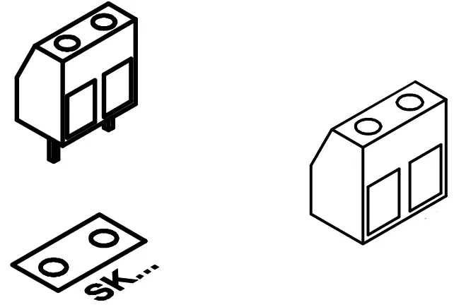
- SK11 : 2p
Fuseholder + Fuse 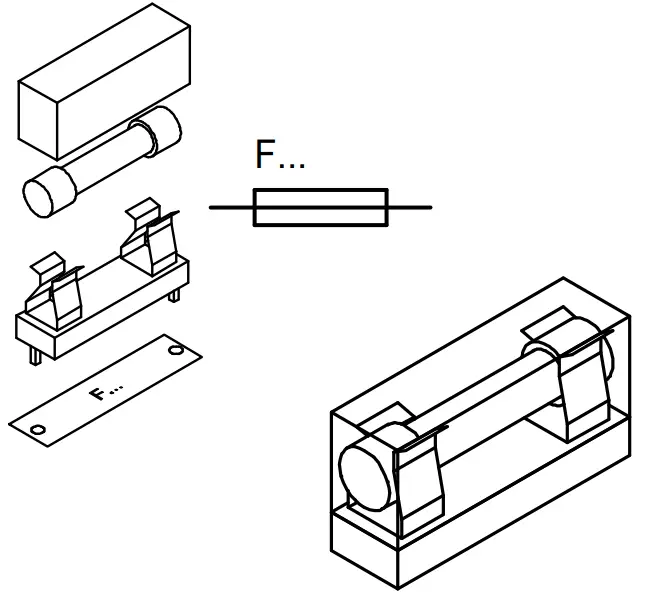
- F1 : 4A (slow)
IC, Check the position of the notch !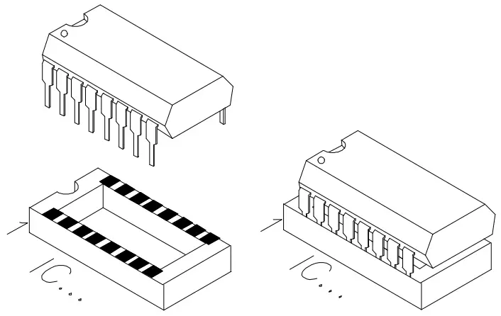
- IC1: VK8044
Programmed PIC16C58B20
Hook-up diagram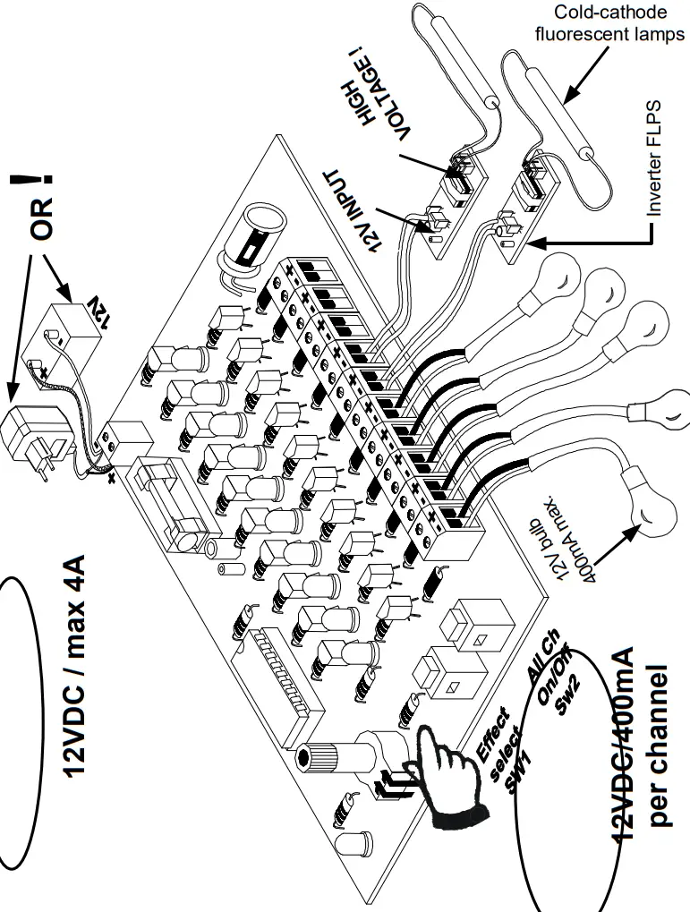
Inspect the complete assembly once more before applying power to the unit !
Use
Connect this kit according to the wiring diagram. LED LD1 will light if the operating voltage is correct. Take all necessary precautions to avoid electroshocks when connecting cold-cathode fluorescent lamps : the inverter ‘FLPS1’ uses a potentially life-threatening voltage.
This kit is available in various countries. Take care to use an appropriate connection or adapter.
Selecting a light effect :
Push button SW1 ‘Effect select’ allows you to choose one of ten available programmes. Hold SW1 to see which effect is currently selected : the LED of that effect will light. The light effect will start running when you release SW1. Press SW1 momentarily to select the next light effect. SW2 enables you to activate or deactivate all channels. Press SW1 to restart the selected light effect. Adjust the speed of the running light with RV1.
The connection cables should be equipped with an approprate strain relief when mounted in a movable housing.
Random light effect :
Hold SW2 pressed before connecting the power supply (the other light patterns shall not work!).
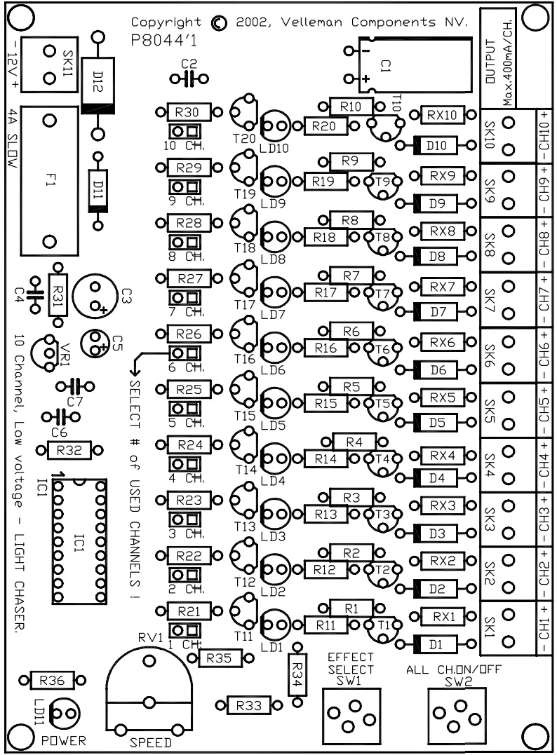
Number of connected channels : Mount a jumper wire on the spot that matches the amount of light channels you would like to use. This will make some light effects adjust to the number of channels used.
Example : Mount a jumper wire on 5 CH if you wish to use 5 light channels.
PCB layout.
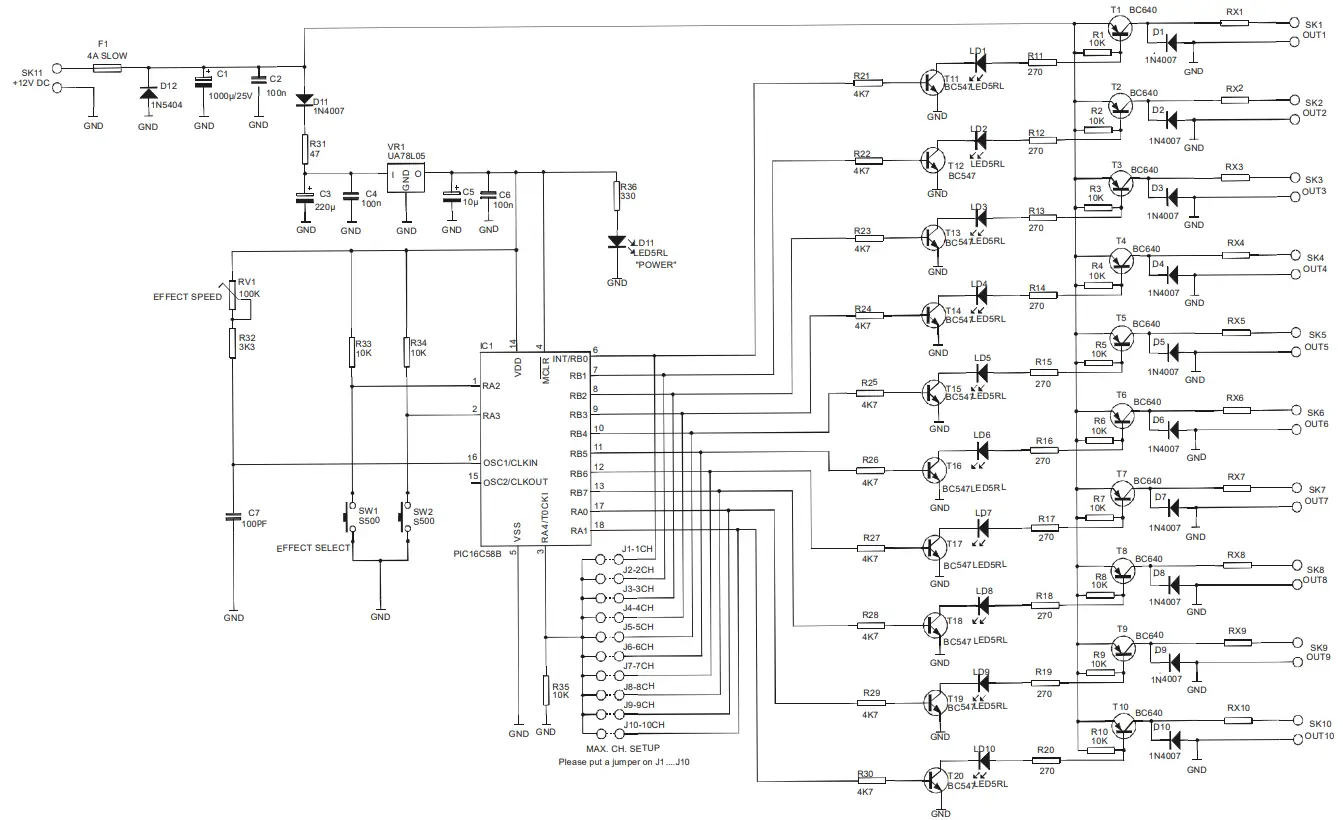
Schematic diagram.
VELLEMAN Components NV
Legen Heirweg 33 9890 Gavere
Belgium Europe
www.velleman.be
www.velleman-kit.com
Modifications and typographical errors reserved
© Velleman Components nv.
H8044IP – 2002 – ED1


